FIP FLS F3.00 User manual
1
FLS F3.00
PADDLEWHEEL
FLOW SENSOR
SAFETY INSTRUCTIONS
General Statements
• Do not install and service the product without following the Instruction
Manual.
• This item is designed to be connected to other instruments which can be
hazardous if used improperly. Read and follow all associated instrument
manuals before using with it.
• Product installation and wiring connections should only be performed by
qualied sta.
• Do not modify product construction.
Installation and Commissioning Statements
• Remove power to the instrument before wiring input and output connections.
• Depressurize and vent the system before installing or removing the sensor.
• Check and conrm the chemical compatibility of the materials in contact
with the liquid.
• Do not exceed maximum specications using the instrument.
• To clean the unit, use only chemical compatible products.

2
General
• Pipe Size Range: DN15 to DN600 (0.5” to 24”) Please refer to Installation
Fittings section for more details
• Flow Rate Range: 0.15 to 8 m/s (0.5 to 25 ft./s)
• Linearity: ± 0.75 % of full scale
• Repeatability: ± 0.5 % of full scale
• Minimum Reynolds Number Required: 4500
• Enclosure: IP68 or IP65
• Wetted Materials:
- sensor Body: CPVC, PVDF, 316L SS
- o-rings: EPDM or FPM
- rotor: ECTFE (Halar®)
- shaft: Ceramic (Al2O3)/316L SS (only for metal sensors)
- bearings: Ceramic (Al2O3)
Specic for F3.00.H
• Supply voltage: 5 to 24 VDC ± 10% regulated
• Supply current: < 30 mA @ 24 VDC
• Output signal:
- square wave
- frequency: 45 Hz per m/s nominal
(13.7 Hz per ft/s nominal)
- type: transistor NPN open collector
- output current: 10 mA max
• Cable length: 8 m (26.4 ft) standard, 300 m (990 ft)maximum
TECHNICAL DATA
PACKING LIST
Please verify that the product is complete and without any damage.
The following items must be included:
• F3.00 Paddlewheel Flow Sensor
• Instruction Manual for F3.00 Paddlewheel Flow Sensor
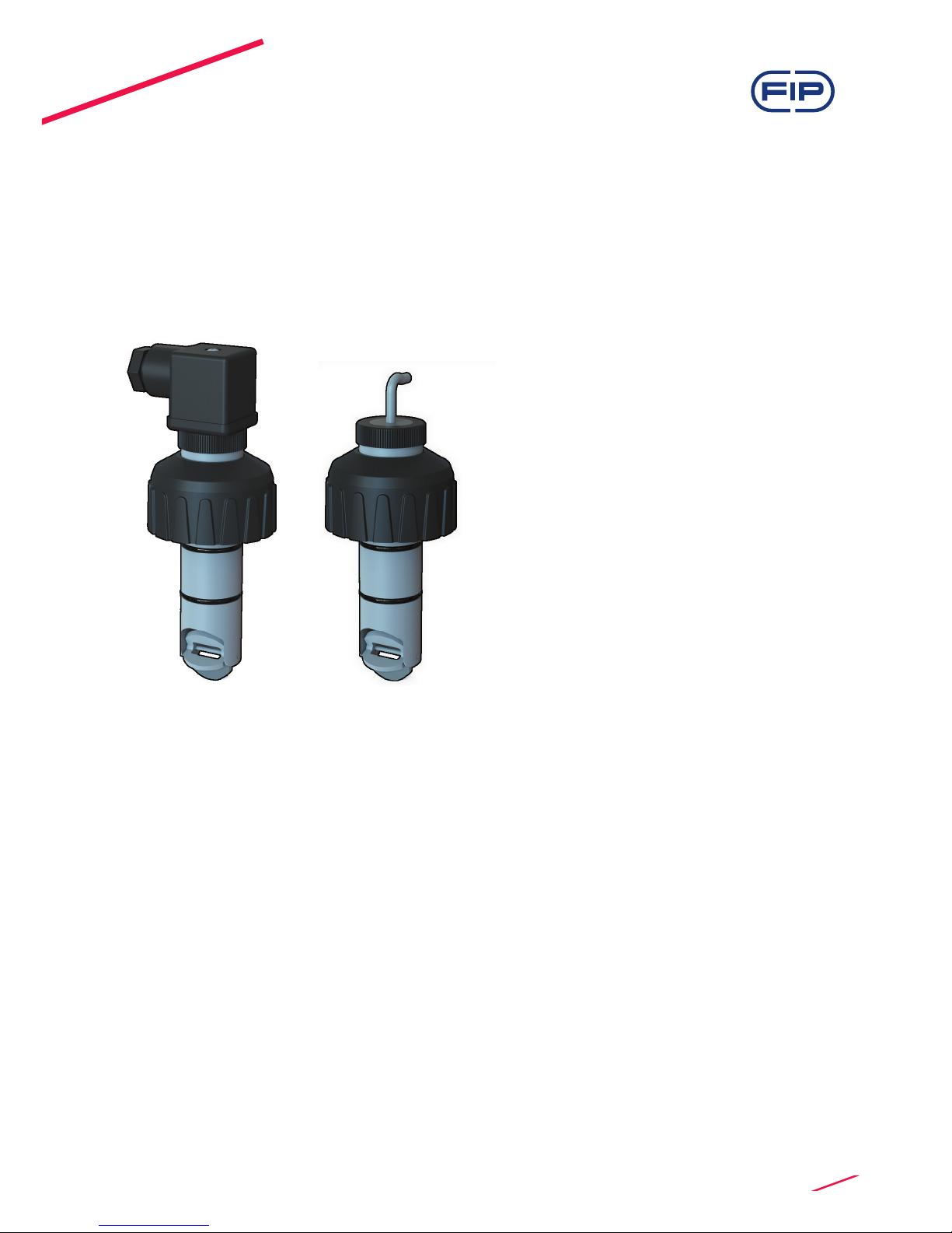
DESCRIPTION
The simple and reliable paddlewheel ow sensor type F3.00 is designed for
use with every kind of solid-free liquids. The sensor can measure ow from
0.15 m/s (0.5 ft/s) producing a frequency output signal highly repeatable.
A rugged construction and a proven technology guarantee exceptional
performances with little or no maintenance required. A dedicated electronic,
with a push-pull output, is available for a safe connection to any
kind of PLC/Instrument digital input. A specially designed family of ttings
ensures an easy and quick installation into all pipe materials in sizes from
DN15 to DN600 (0.5” to 24”).

3
Specic for F3.00.C
• Supply voltage: 3 to 5 VDC regulated or
3.6 Volt Lithium battery
• Supply current: < 10 µA max
• Output signal:
- square wave
- frequency: 45 Hz per m/s nominal
(13.7 Hz per ft/s nominal)
- min. input impedance: 100 KΩ
• Cable length: 8 m (26.4 ft) standard, 16 m (52.8 ft) maximum
Specic for F3.00.P
• Supply voltage: 12 to 24 VDC ± 10% regulated
• Supply current: < 30 mA @ 24 VDC
• Output signal:
- square wave
- frequency: 45 Hz per m/s nominal
(13.7 Hz per ft/s nominal)
- type: Push-Pull (for connection to NPN and PNP inputs)
- output current: 20 mA max
• Cable length: 8 m (26.4 ft) standard, 300 m (990 ft) maximum
Standards & Approvals
• Manufactured under ISO 9001
• Manufactured under ISO 14001
• CE
• RoHS Compliant
• GOST R
4
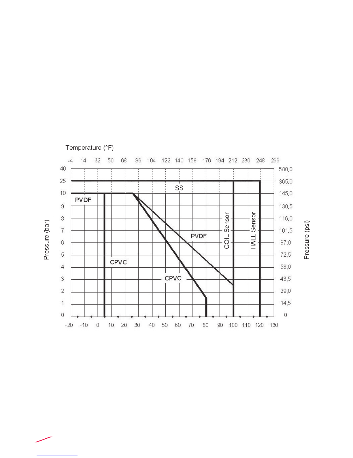
Maximum Operating Pressure / Temperature (25 years lifetime)
F3.00.H or F3.00.P Sensor
• CPVC body:
- 10 bar (145 psi) @ 25°C (77°F)
- 1,5 bar (22 psi) @ 80° C (176°F)
• PVDF body:
- 10 bar (145 psi) @ 25°C (77°F)
- 2,5 bar (36 psi) @ 100°C (212°F)
• SS body:
- 25 bar (363 psi) @ 120°C (248°F)
F3.00.C Sensor
• CPVC body:
- 10 bar (145 psi) @ 25°C (77°F)
- 1,5 bar (22 psi) @ 80° C (176°F)
• PVDF body:
- 10 bar (145 psi) @ 25°C (77°F)
- 2,5 bar (36 psi) @ 100°C (212°F)
• SS body:
- 25 bar (363 psi) @ 100°C (212°F)
5
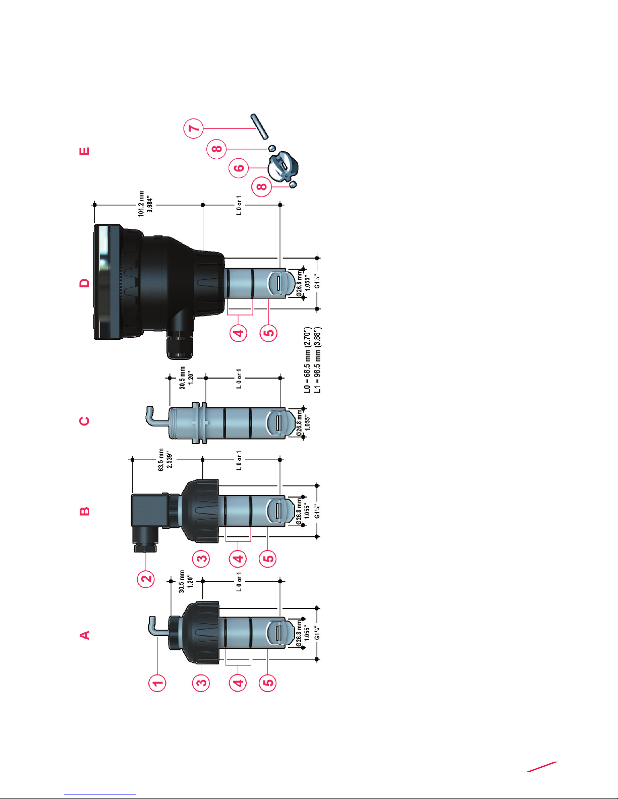
DIMENSIONS
AF3.00 IP68 Remote Sensor
BF3.00 IP65 Remote Sensor
CF3.01 Compact Sensor
DF3.01 Compact Sensor + Transmitter
(sold separately)
EPaddlewheel system
1Electrical cable: 8 m. (26.4 ft) standard
24 pole cable plug according
to DIN 43650-B/ISO 6952
3 UPVC cap for installation into ttings
4O-Ring seals available in EPDM or FPM
5CPVC, PVDF, Stainless Steel
sensor body
6ECTFE Halar®(registered trademark
of Ausimont-Solvay) Open-cell rotor
7Ceramic shaft
8Ceramic bearings
6
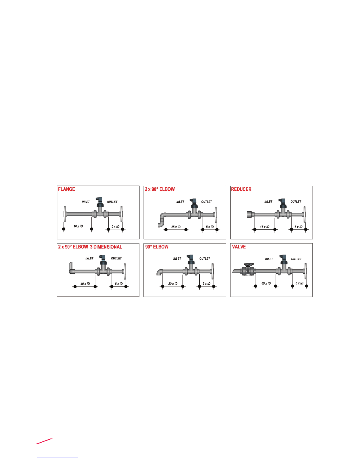
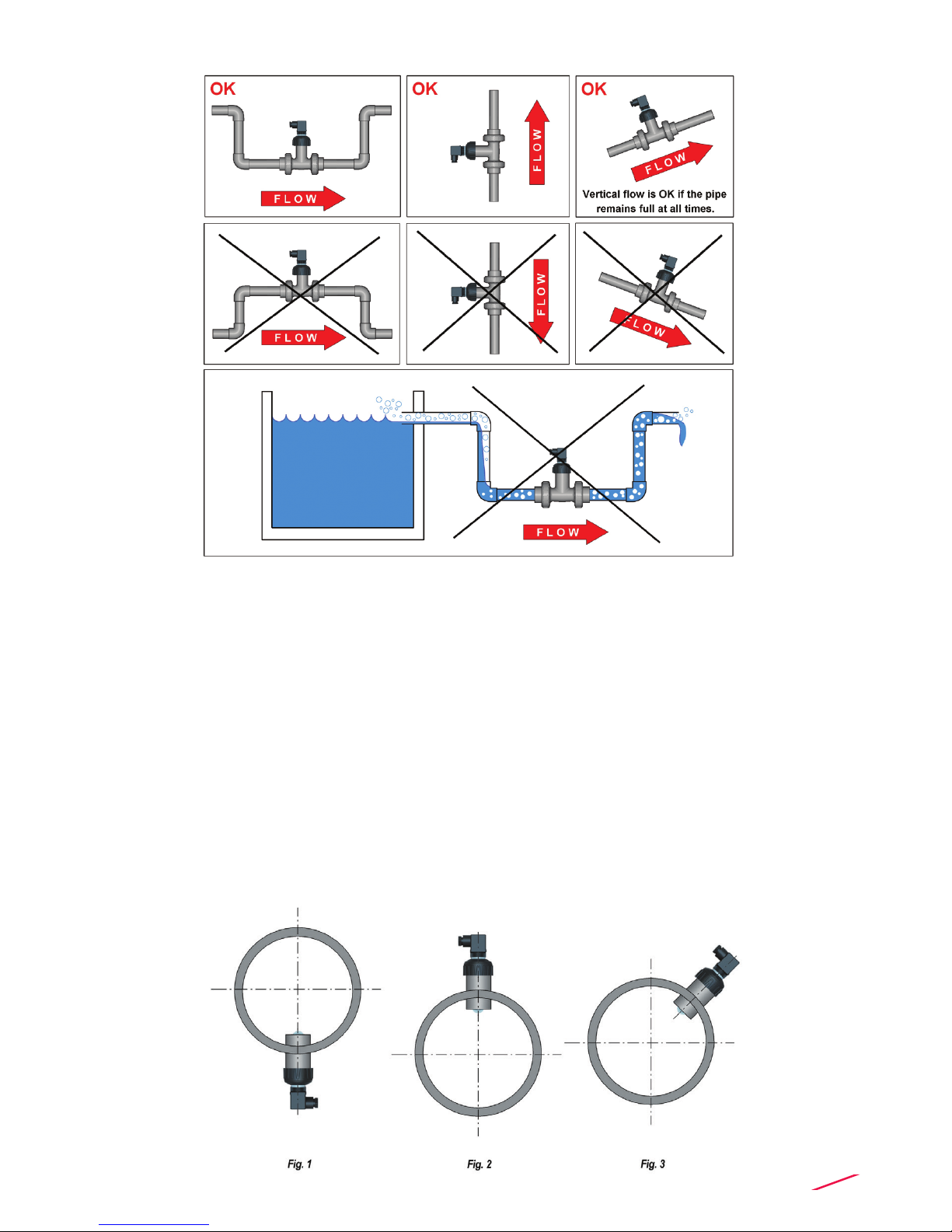
Fig.1
INSTALLATION
Pipe Location
• The six most common installation congurations shown in g. 1 help in
selecting the best location in the pipeline for paddlewheel ow sensor as well
for magmeter ow sensor.
• The three congurations in g. 2 ensure that the pipe is always full: for a
correct measurement the sensor can NOT be exposed to air bubbles at any
time.
• The three installations in Fig. 3 should be avoided unless you are absolutely
sure the sensor is not exposed to air bubbles.
• In gravity-ow systems the connection to the tank must be designed so the
level does not drop below the outlet: this to avoid pipe to draw air in from the
tank causing a inaccurate measurement of sensor (see Fig. 4).
• For more information, please refer to EN ISO 5167-1.
• Always maximize distance between ow sensors and pumps.
7
Fig.2
Fig.3
Fig.4
Mounting position
Measuring part of sensor (rotor for paddlewheel and pins for magmeter)
should be positioned at 12% of ID where, basing on insertion theory, average
velocity can be measured.
The reading accuracy of insertion ow sensors can be aected by:
• air bubbles;
• sediments;
• friction between shaft and bearings (only for paddlewheel).
In a horizontal pipe runs, the mounting position to get the best performances is
at a 45° angle (Fig. 3) to avoid air bubbles as well sediments. Vertical position
(Fig. 2) can be chosen in case air bubbles are not present. Do not mount the
sensor on the bottom of the pipe (Fig. 1) if sediments are likely. Do not mount
paddlewheel at 90° otherwise friction can aect measurement.
Installation in a vertical pipe runs can be done xing any orientation.
Upward ow is preferred to ensure full pipe.
8
WIRING
General recommendation
• Always ensure the power supply is switched o before working on the sensor.
• Always use a high quality (regulated) DC voltage supply.
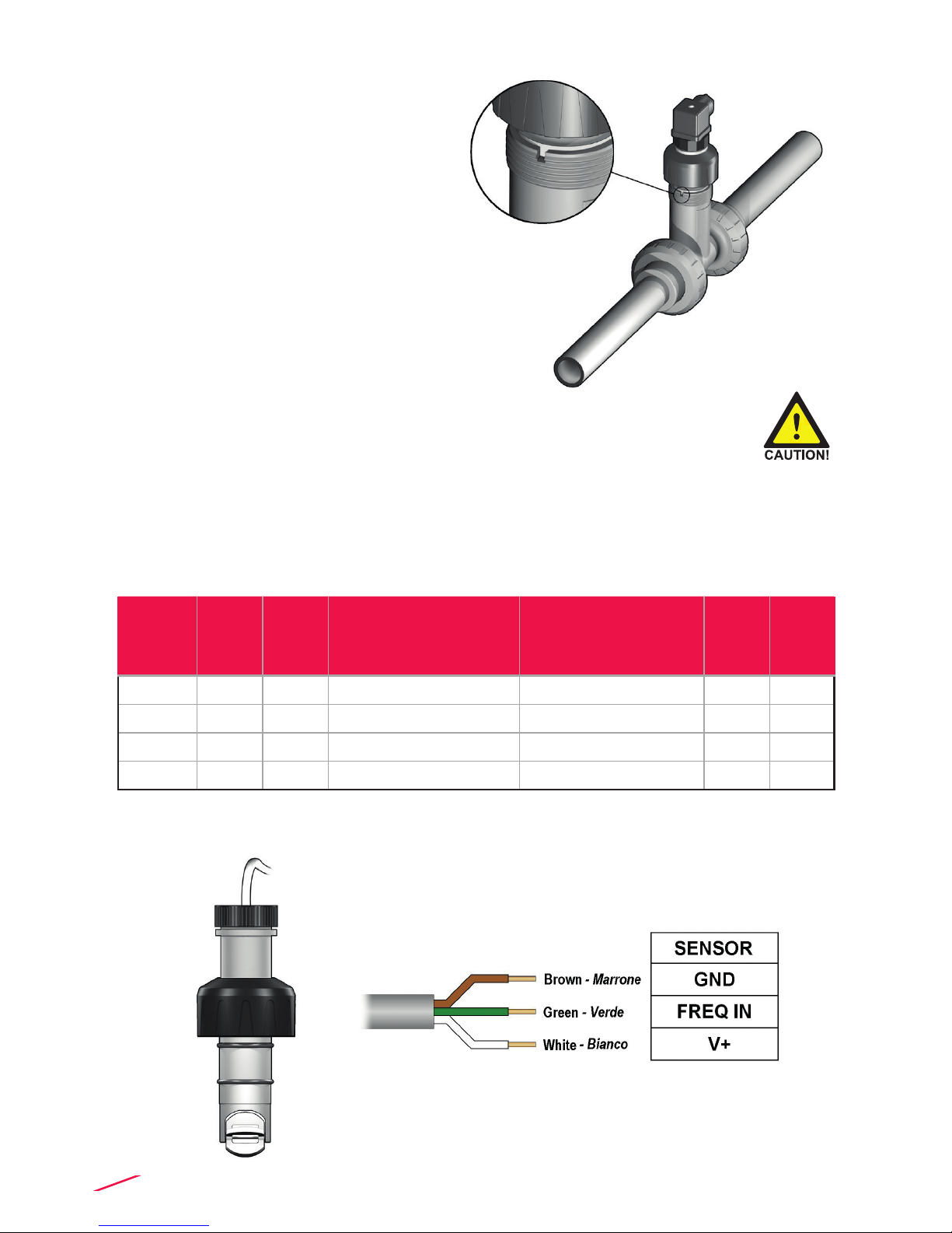
WIRING DIAGRAMS
F3.00.H IP68 Sensor Connection to FLS Instruments (except M9.20)
Process connection
1. Lubricate the sensor O-rings
with a silicone lubricant. Do
not use any petroleum based
lubricant that may damage the
O-rings.
2. Lower the sensor into the tting
making sure the alignment tab is
seated in the tting notch.
3. Hand tighten the sensor cap.
Do not use any tool otherwise
cap and/or tting threads may be
damaged.
M9.02 M9.50
M9.07
M9.08
M9.03 (FLOW SENSOR 2)
M9.03 (FLOW SENSOR 1)M9.20
M9.00 M9.10
GND 5 30 16 30 7 37
FREQ. IN 6 28 14 28 8 36
V+ 7 27 13 27 9 35
DIR 6B - 15 29 - -
9
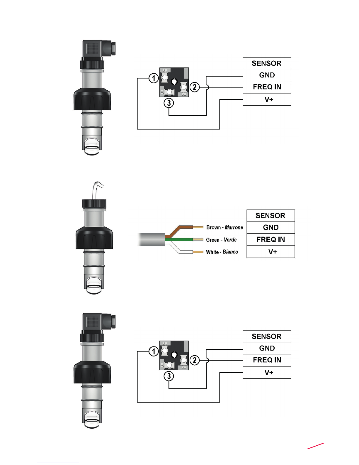
F3.00.H IP65 Sensor Connection to FLS Instruments (except M9.20)
F3.00.C IP65 Sensor Connection to FLS Instruments (only for M9.20)
F3.00.C IP68 Sensor Connection to FLS Instruments (only for M9.20)

10
F3.00.P IP68 Sensor Connection to PLC with NPN Input
F3.00.P IP68 Sensor Connection to PLC with PNP Input
F3.00.P IP65 Sensor Connection to PLC with NPN Input
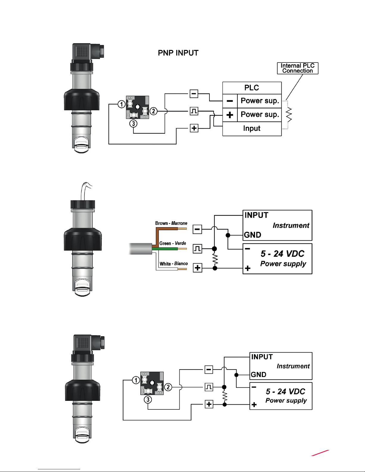
11
F3.00.P IP65 Sensor Connection to PLC with PNP Input
F3.00.H IP68 Sensor Connection to Other Brand Instruments
2.7Kohm Pull-up resistor may be
F3.00.H IP65 Sensor Connection to Other Brand Instruments
2.7Kohm Pull-up resistor may be

12
F3.00.C IP68 Sensor Connection to Other Brand Instruments
F3.00.C IP65 Sensor Connection to Other Brand Instruments
2.7Kohm Pull-up resistor may be
13
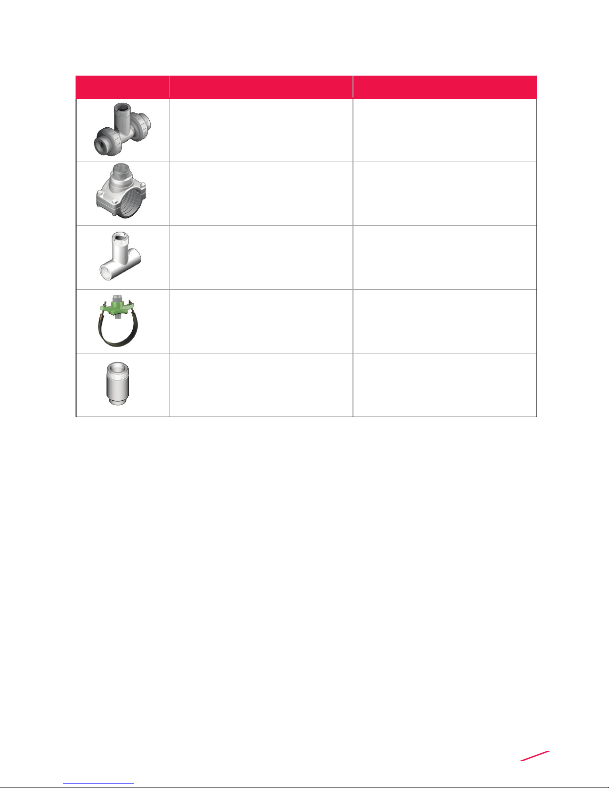
INSTALLATION FITTINGS
Type Description
Plastic Tees
• Size: d20 to d50 (0.5” to 1.5”)
• Materials: PVC, C-PVC, PP, PVDF
PVC-U Clamp Saddles
• Size: d63 to d225 (2” to 8”)
• Insert Materials: C-PVC, PVDF
316L SS Tees • Size: d63 to d315
• Materials: PVC, C-PVC, PP, PE
Metal Strap-on Saddles
• Size: DN80 to DN450
• Insert Material: C-PVC
• Special order for other sizes
316L SS Weld-on Adapters • Size: d50 to d600 (1.5” to 24”)
14
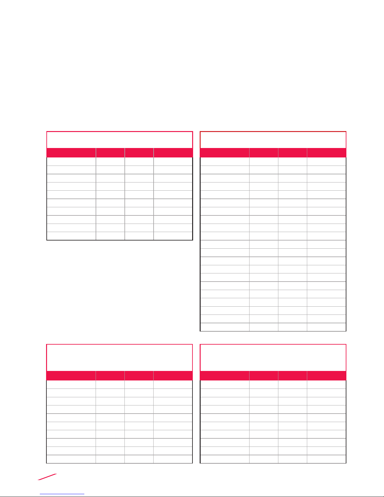
K-FACTOR TABLES
K-Factor is the number of pulses which a sensor produces for one liter of
measured uid. Here below all K-Factors for water at room temperature are
listed.
K-Factor values can depend on the installation conditions. K-Factor has to
divide the frequency generated by F3.00 in order to achieve the ow rate (l/s).
Please contact your dealer for K-Factor values not included in the table.
Installation on PVC pipes
ISO Metric Clamp Saddles for ISO SDR 21 pipes
(PN10 up to d 90mm, PN12,5 from d 110mm)
Part No. DN d K-Factor
SVIC063BVC 50 63 21,69
SVIC075BVC 65 75 14,98
SVIC090BVC 80 90 9,88
SVIC110BVC 100 110 6,06
SVIC125BVC 110 125 4,59
SVIC140BVC 125 140 3,59
SVIC160BVC 150 160 2,69
SVIC200BVC 180 200 1,65
SVIC225BVC 200 225 1,28
SVIC063DVC 50 63 21,69
SVIC075DVC 65 75 14,98
SVIC090DVC 80 90 9,88
SVIC110DVC 100 110 6,06
SVIC125DVC 110 125 4,59
SVIC140DVC 125 140 3,59
SVIC160DVC 150 160 2,69
SVIC200DVC 180 200 1,65
SVIC225DVC 200 225 1,28
SMIC250IVC 225 250 1,01
SMIC280IVC 250 280 0,79
SMIC315IVC 280 315 0,61
ISO Metric PVC Tee Fittings for ISO SDR
21 pipes (female ends for solvent welding)
Part No. DN d K-Factor
TFIV20B 15 20 235,45
TFIV25B 20 25 142,46
TFIV32B 25 32 91,53
TFIV40B 32 40 51,57
TFIV50B 40 50 42,89
TFIV20D 15 20 235,45
TFIV25D 20 25 142,46
TFIV32D 25 32 91,53
TFIV40D 32 40 51,57
TFIV50D 40 50 42,89
BSP Female Threaded PVC Tee Fittings
for BS PN12 pipes
(parallel threaded female ends)
Part No. DN R K-Factor
TFFV20B 15 1/2" 235,45
TFFV25B 20 3/4" 142,46
TFFV32B 25 1" 91,53
TFFV40B 32 1" 1/4 51,57
TFFV50B 40 1" 1/2 42,89
TFFV20D 15 1/2" 235,45
TFFV25D 20 3/4" 142,46
TFFV32D 25 1" 91,53
TFFV40D 32 1" 1/4 51,57
TFFV50D 40 1" 1/2 42,89
BS Solvent Welding PVC Tee Fittings
for BS PN12 pipes
(female ends for solvent welding)
Part No. DN d K-Factor
TFLV20B 15 1/2" 235,45
TFLV25B 20 3/4" 142,46
TFLV32B 25 1" 91,53
TFLV40B 32 1" 1/4 51,57
TFLV50B 40 1" 1/2 42,89
TFLV20D 15 1/2" 235,45
TFLV25D 20 3/4" 142,46
TFLV32D 25 1" 91,53
TFLV40D 32 1" 1/4 51,57
TFLV50D 40 1" 1/2 42,89
"

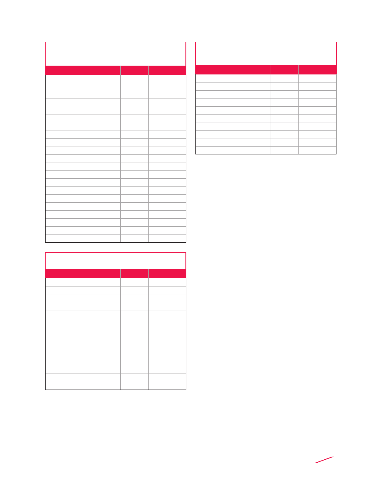
15
BS Clamp Saddles for BS PN12 pipes
Part No. DN d K-Factor
SVLC2.0BVM 50 2" 24,10
SVLC3.0BVM 80 3" 10,29
SVLC4.0BVM 100 4" 5,72
SVLC6.0BVM 150 6" 2,48
SVLC8.0BVM 200 8" 1,34
SVLC2.0DVM 50 2" 24,10
SVLC3.0DVM 80 3" 10,29
SVLC4.0DVM 100 4" 5,72
SVLC6.0DVM 150 6" 2,48
SVLC8.0DVM 200 8" 1,34
ASTM SCH. 80 Clamp Saddles
for ASTM SCH. 80 pipes
Part No. SIZE d K-Factor
SVAC2.0BVM 2.00" - 29,74
SVAC2.5BVM 2.50" - 20,25
SVAC3.0BVM 3.00" - 12,36
SVAC4.0BVM 4.00" - 6,47
SVAC5.0BVM 5.00" - 4,00
SVAC6.0BVM 6.00" - 2,68
SVAC8.0BVM 8.00" - 1,46
SVAC2.0DVM 2.00" - 29,74
SVAC2.5DVM 2.50" - 20,25
SVAC3.0DVM 3.00" - 12,36
SVAC4.0DVM 4.00" - 6,47
SVAC5.0DVM 5.00" - 4,00
SVAC6.0DVM 6.00" - 2,68
SVAC8.0DVM 8.00" - 1,46
NPT Female Threaded PVC Tee Fittings
for ASTM SCH. 80 pipes
(NPT threaded female ends)
Part No. SIZE R K-Factor
TFNV20B 0.50" 1/2" 235,45
TFNV25B 0.75" 3/4" 142,46
TFNV32B 1.00" 1" 91,53
TFNV40B 1.25" 1" 1/4 51,57
TFNV50B 1.50" 1" 1/2 42,89
TFNV20D 0.50" 1/2" 235,45
TFNV25D 0.75" 3/4" 142,46
TFNV32D 1.00" 1" 91,53
TFNV40D 1.25" 1" 1/4 51,57
TFNV50D 1.50" 1" 1/2 42,89
ASTM SCH. 80 PVC Tee Fittings
for ASTM SCH. 80 pipes
(female ends for solvent welding)
Part No. SIZE d K-Factor
TFAV20B 0.50" 1/2" 235,45
TFAV25B 0.75" 3/4" 142,46
TFAV32B 1.00" 1" 91,53
TFAV40B 1.25" 1" 1/4 51,57
TFAV50B 1.50" 1" 1/2 42,89
TFAV20D 0.50" 1/2" 235,45
TFAV25D 0.75" 3/4" 142,46
TFAV32D 1.00" 1" 91,53
TFAV40D 1.25" 1" 1/4 51,57
TFAV50D 1.50" 1" 1/2 42,89

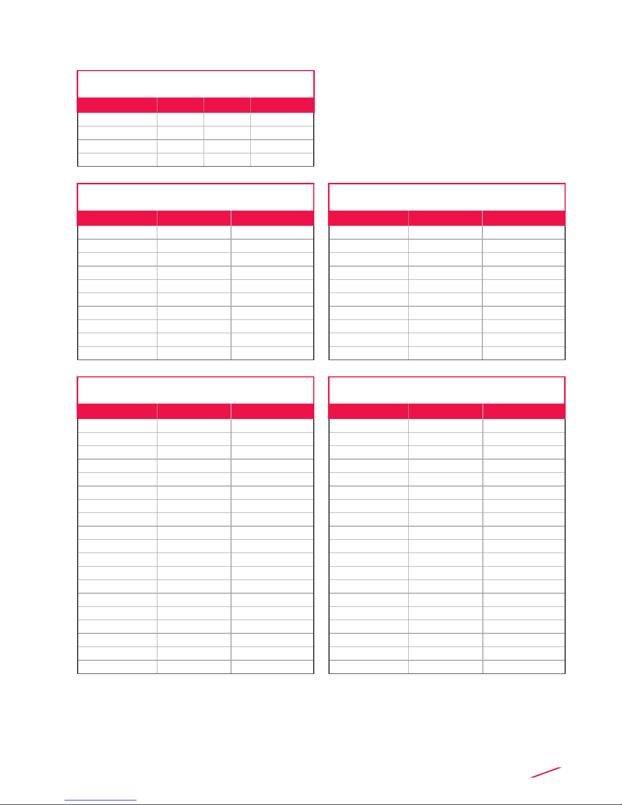
16
Installation on C-PVC pipes
Installation on PP pipes
ISO Metric CPVC Tee Fitings for ISO SDR 21
pipes (female ends for solvent welding)
Part No. DN d K-Factor
TFIC20B 15 20 235,45
TFIC25B 20 25 142,46
TFIC32B 25 32 91,53
TFIC40B 32 40 51,57
TFIC50B 40 50 42,89
TFIC20D 15 20 235,45
TFIC25D 20 25 142,46
TFIC32D 25 32 91,53
TFIC40D 32 40 51,57
TFIC50D 40 50 42,89
ISO Metric PP Tee Fittings for ISO SDR 11 pipes
(female ends for socket welding)
Part No. DN d K-Factor
TFIM20B 15 20 212,17
TFIM25B 20 25 135,32
TFIM32B 25 32 89,36
TFIM40B 32 40 48,94
TFIM50B 40 50 42,10
TFIM20D 15 20 212,17
TFIM25D 20 25 135,32
TFIM32D 25 32 89,36
TFIM40D 32 40 48,94
TFIM50D 40 50 42,10
BSP Female Threaded PP Tee Fittings
for BS pipes (parallel threaded female ends)
Part No. DN R K-Factor
TFFM20B 15 1/2" 212,17
TFFM25B 20 3/4" 135,32
TFFM32B 25 1" 89,36
TFFM40B 32 1" 1/4 48,94
TFFM50B 40 1" 1/2 42,10
TFFM20D 15 1/2" 212,17
TFFM25D 20 3/4" 135,32
TFFM32D 25 1" 89,36
TFFM40D 32 1" 1/4 48,94
TFFM50D 40 1" 1/2 42,10
ISO Clamp Saddles for ISO SDR 21 pipes
Part No. DN d K-Factor
SVIC063BVC 50 63 21,69
SVIC075BVC 65 75 14,98
SVIC090BVC 80 90 9,88
SVIC110BVC 100 110 6,06
SVIC125BVC 110 125 4,59
SVIC140BVC 125 140 3,59
SVIC160BVC 150 160 2,69
SVIC200BVC 180 200 1,65
SVIC225BVC 200 225 1,28
SVIC063DVC 50 63 21,69
SVIC075DVC 65 75 14,98
SVIC090DVC 80 90 9,88
SVIC110DVC 100 110 6,06
SVIC125DVC 110 125 4,59
SVIC140DVC 125 140 3,59
SVIC160DVC 150 160 2,69
SVIC200DVC 180 200 1,65
SVIC225DVC 200 225 1,28
SMIC250IVC 225 250 1,01
SMIC280IVC 250 280 0,79
SMIC315IVC 280 315 0,61
17
NPT Female Threaded PP Tee Fittings
for ASTM SCH.80 pipes
(NPT threaded female ends)
Part No. DN d K-Factor
TFNM20B 0.50" 1/2" 212,17
TFNM25B 0.75" 3/4" 135,32
TFNM32B 1.00" 1" 89,36
TFNM40B 1.25" 1" 1/4 48,94
TFNM50B 1.50" 1" 1/2 42,10
TFNM20D 0.50" 1/2" 212,17
TFNM25D 0.75" 3/4" 135,32
TFNM32D 1.00" 1" 89,36
TFNM40D 1.25" 1" 1/4 48,94
TFNM50D 1.50" 1" 1/2 42,10
ISO Clamp Saddles for ISO SDR 21 pipes
Part No. DN d K-Factor
SVIC063BME 50 63 27,50
SVIC075BME 65 75 18,56
SVIC090BME 80 90 12,44
SVIC110BME 100 110 7,59
SVIC125BME 110 125 5,77
SVIC140BME 125 140 4,49
SVIC160BME 150 160 3,38
SVIC200BME 180 200 2,07
SVIC225BME 200 225 1,60
SVIC063DME 50 63 27,50
SVIC075DME 65 75 18,56
SVIC090DME 80 90 12,44
SVIC110DME 100 110 7,59
SVIC125DME 110 125 5,77
SVIC140DME 125 140 4,49
SVIC160DME 150 160 3,38
SVIC200DME 180 200 2,07
SVIC225DME 200 225 1,60
SMIC250IME 225 250 1,27
SMIC280IME 250 280 0,99
SMIC315IME 280 315 0,77
ASTM SCH. 80 Clamp Saddles
for ASTM SCH. 80 pipes
Part No. SIZE d K-Factor
SVAC2.0BME 2.00" - 29,83
SVAC2.5BME 2.50" - 20,37
SVAC3.0BME 3.00" - 12,36
SVAC4.0BME 4.00" - 6,47
SVAC5.0BME 5.00" - 3,92
SVAC6.0BME 6.00" - 1,53
SVAC8.0BME 8.00" - 1,44
SVAC2.0DME 2.00" - 29,83
SVAC2.5DME 2.50" - 20,37
SVAC3.0DME 3.00" - 12,36
SVAC4.0DME 4.00" - 6,47
SVAC5.0DME 5.00" - 3,92
SVAC6.0DME 6.00" - 1,53
SVAC8.0DME 8.00" - 1,44

18
Installation on PVDF pipes
Installation on PE pipes
ISO Metric PVDF Tee Fittings for ISO SDR 33
pipes (female ends for socket welding)
Part No. DN d K-Factor
TFIF20B 15 20 225,06
TFIF25B 20 25 139,38
TFIF32B 25 32 94,66
TFIF40B 32 40 51,37
TFIF50B 40 50 43,07
TFIF20D 15 20 225,06
TFIF25D 20 25 139,38
TFIF32D 25 32 94,66
TFIF40D 32 40 51,37
TFIF50D 40 50 43,07
ISO Metric PVC Tee Fittings
for PE SDR 11 pipes (PE end connectors
for electrofusion or butt welding)
Part No. DN d K-Factor
TFIV20BE 15 20 193,70
TFIV25BE 20 25 134,07
TFIV32BE 25 32 85,29
TFIV40BE 32 40 48,68
TFIV50BE 40 50 41,68
TFIV20DE 15 20 193,70
TFIV25DE 20 25 134,07
TFIV32DE 25 32 85,29
TFIV40DE 32 40 48,68
TFIV50DE 40 50 41,68
ISO Clamp Saddles for ISO SDR 33 pipes
Part No. DN d K-Factor
SVIF063BF 50 63 20,58
SVIF 075BF 65 75 14,09
SVIF 090BF 80 90 9,29
SVIF 110BF 100 110 5,69
SVIF 125BF 110 125 4,31
SVIF 140BF 125 140 3,36
SVIF 160BF 150 160 2,52
SVIF 200BF 180 200 1,55
SVIF 225BF 200 225 1,20
SVIF 063DF 50 63 20,58
SVIF 075DF 65 75 14,09
SVIF 090DF 80 90 9,29
SVIF 110DF 100 110 5,69
SVIF 125DF 110 125 4,31
SVIF 140DF 125 140 3,36
SVIF 160DF 150 160 2,52
SVIF 200DF 180 200 1,55
SVIF 225DF 200 225 1,20
ISO Clamp Saddles for PE SDR 11 pipes
Part No. DN d K-Factor
SVIC063BME 50 63 27,39
SVIC075BME 65 75 18,75
SVIC090BME 80 90 12,41
SVIC110BME 100 110 7,57
SVIC125BME 110 125 5,76
SVIC140BME 125 140 4,49
SVIC160BME 150 160 3,37
SVIC200BME 180 200 2,02
SVIC225BME 200 225 1,60
SVIC063DME 50 63 27,39
SVIC075DME 65 75 18,75
SVIC090DME 80 90 12,41
SCIC110DME 100 110 7,57
SVIC125DME 110 125 5,76
SVIC140DME 125 140 4,49
SVIC160DME 150 160 3,37
SVIC200DME 180 200 2,02
SVIC225DME 200 225 1,60
SMIC250IME 225 250 1,27
SMIC280IME 250 280 0,99
SMIC315IME 280 315 0,77
19
Installation on Metal pipes
316L SS Threaded Tees
(BSP Female Threads)
Part No. DN R K-Factor
TFFX20 15 1/2" -
TFFX25 20 3/4 157,06
TFFX32 25 1" 92,84
TFFX40 32 1" 1/4 51,52
Metal Strap-on Saddles
mounted on Cast Iron pipes
Part No. DN K-Factor
SZIC080I 80 10,22
SZIC100I 100 6,01
SZIC125I 125 3,64
SZIC150I 150 2,46
SZIC200I 200 1,28
SZIC250I 250 0,79
SZIC300I 300 0,53
SZIC350I 350 0,4
SZIC400I 400 0,31
SZIC450I 450 0,24
Metal Strap-on Saddles
mounted on Other Metal pipes
Part No. DN K-Factor
SZIC080I 80 9,61
SZIC100I 100 5,22
SZIC125I 125 3,31
SZIC150I 150 2,22
SZIC200I 200 1,23
SZIC250I 250 0,75
SZIC300I 300 0,52
SZIC350I 350 0,43
SZIC400I 400 0,32
SZIC450I 450 -
316L SS Weld-on Adapters
mounted on Other Metal pipes
Part No. DN K-Factor
WAIXL0 40 36,17
WAIXL0 50 23,71
WAIXL0 60 -
WAIXL0 65 13,93
WAIXL0 80 9,61
WAIXL0 100 5,22
WAIXL0 110 -
WAIXL0 125 3,31
WAIXL0 150 2,22
WAIXL0 175 -
WAIXL0 200 1,23
WAIXL1 225 0.75
WAIXL1 250 0,52
WAIXL1 300 0,43
WAIXL1 350 0,32
WAIXL1 400 -
WAIXL1 450 0,20
WAIXL1 500 -
WAIXL1 600 0,14
316L SS Weld-on Adapters
mounted on Cast Iron pipes
Part No. DN K-Factor
WAIXL0 40 -
WAIXL0 50 -
WAIXL0 60 19,78
WAIXL0 65 -
WAIXL0 80 10,22
WAIXL0 100 6,01
WAIXL0 110 -
WAIXL0 125 3,64
WAIXL0 150 2,46
WAIXL0 175 -
WAIXL0 200 1,28
WAIXL1 225 -
WAIXL1 250 0,79
WAIXL1 300 0,53
WAIXL1 350 0,40
WAIXL1 400 0,31
WAIXL1 450 0,24
WAIXL1 500 0,20
WAIXL1 600 0,14

20
ORDERING DATA
F3.00.H.XX Paddlewheel Flow Sensors (Remote version)
Part No. Version Power
supply Length
Main
wetted
materials
Enclosure Flow Rate
Range
Weight
(gr.)
F3.00.H.01 Hall 5 - 24 VDC L0 CPVC/ EPDM IP68 0.15 to 8 m/s
(0.5 to 25 ft./s.) 250
F3.00.H.02 Hall 5 - 24 VDC L0 CPVC/FPM IP68 0.15 to 8 m/s
(0.5 to 25 ft./s.) 250
F3.00.H.03 Hall 5 - 24 VDC L1 CPVC/ EPDM IP68 0.15 to 8 m/s
(0.5 to 25 ft./s.) 300
F3.00.H.04 Hall 5 - 24 VDC L1 CPVC/FPM IP68 0.15 to 8 m/s
(0.5 to 25 ft./s.) 300
F3.00.H.05 Hall 5 - 24 VDC L0 PVDF/EPDM IP68 0.15 to 8 m/s
(0.5 to 25 ft./s.) 250
F3.00.H.06 Hall 5 - 24 VDC L0 PVDF/FPM IP68 0.15 to 8 m/s
(0.5 to 25 ft./s.) 250
F3.00.H.07 Hall 5 - 24 VDC L1 PVDF/EPDM IP68 0.15 to 8 m/s
(0.5 to 25 ft./s.) 300
F3.00.H.08 Hall 5 - 24 VDC L1 PVDF/FPM IP68 0.15 to 8 m/s
(0.5 to 25 ft./s.) 300
F3.00.H.09 Hall 5 - 24 VDC L0 316SS/EPDM IP68 0.15 to 8 m/s
(0.5 to 25 ft./s.) 600
F3.00.H.10 Hall 5 - 24 VDC L0 316SS/FPM IP68 0.15 to 8 m/s
(0.5 to 25 ft./s.) 600
F3.00.H.11 Hall 5 - 24 VDC L1 316SS/EPDM IP68 0.15 to 8 m/s
(0.5 to 25 ft./s.) 650
F3.00.H.12 Hall 5 - 24 VDC L1 316SS/FPM IP68 0.15 to 8 m/s
(0.5 to 25 ft./s.) 650
F3.00.H.13 Hall 5 - 24 VDC L0 CPVC/EPDM IP65 0.15 to 8 m/s
(0.5 to 25 ft./s.) 250
Correction formula for K-Factor calculation according to real internal
diameter:
K-Factor_NEW = (K-Factor x ID²) / ID_NEW²
ID = Value in the table for the internal diameter (in mm)
ID_NEW = New value for the real internal diameter (always in mm)
K-Factor = Value in the table
K-Factor_NEW = New K-Factor value for the specied internal diameter
Example:
Nominal Pipe Size (DN) = 100 mm
New Internal Diameter = 104 mm
Forumla: K-Factor_NEW = (51.02 x 100²) / 104² = 20,52
This manual suits for next models
3
Table of contents
Other FIP Accessories manuals

Popular Accessories manuals by other brands


Thule
Thule 11000200 instructions

Veris Industries
Veris Industries AG01E installation guide

Omni Ultraviolet
Omni Ultraviolet UV WAND SANITIZER manual

Tri-Tronics
Tri-Tronics SMARTEYE SmartDot Installation instructions manual

inventum
inventum HN5211L instruction manual

KROHNE
KROHNE OPTIFLUX 2000 quick start


