FIP FLS F3.00.W User manual

1
FLS F3.00.W
WIRELESS PADDLEWHEEL
FLOW SENSOR
SAFETY INSTRUCTIONS
General Statements
• Do not install and service the product without following the Instruction
Manual.
• This item is designed to be connected to other instruments which can be
hazardous if used improperly. Read and follow all associated instrument
manuals before using with it.
• Product installation and wiring connections should only be performed by
qualied sta.
• Do not modify product construction.
• To optimize the system functionality, please refer to section “System
location”.
Installation and Commissioning Statements
• Remove power to the instrument before wiring input and output connections.
• Do not exceed maximum specications using the instrument.
• To clean the unit, use only chemical compatible products.

2
PACKING LIST
Please verify that the product is complete and without any damage.
The following items must be included:
• F3.00.W Bluetooth®system: paddlewheel with integrated transmitter, PCB
receiver, DIN bar case adapter, PCB receiver spacers for wall mounting box
installation
• Instruction Manual for F3.00.W Bluetooth®system
DESCRIPTION
The new FLS Wireless Paddlewheel Flow Sensor F3.00.W is an innovative
system for ow monitoring based on Bluetooth®transmission technology.
The paddlewheel ow sensor is provided with an integrated transmitter that
communicates with the receiver. The receiver is compatible with FLS monitors
(from release 5.0.1.) or other devices which can provide digital inputs. For
former releases please update the item downloading the latest software
release on snet.it.
The FLS F3.00.W is a reliable solution for every kind of solid-free liquid. Easy
and quick to install, it is suitable for pipes in dierent materials,
sized from DN15 to DN600 (0.5’’ to 24’’).
WASTE OF ELECTRIC AND ELECTRONIC
EQUIPMENT
This product falls under the eld of application of Directive 2012/19/EU
concerning electric and electronic equipment waste management (WEEE).
The equipment must not be discarded with domestic waste since made up of
various materials that can be recycled at suitable centres. Apply to your town
authorities as to the location of disposal sites that can receive the product for
disposal and subsequent correct recycling.
Please also remember that the distributor is required to freely dispose of old
products when an equivalent product is purchased.
The product is not potentially harmful to human health and the environment
since it does not contain harmful substances as per Directive 2011/65/EU
(RoHS) but can negatively impact the environment if littered.
Carefully read the instructions before using the equipment for the rst time.
Please do not use the product in any way other than its intended use since
this could cause electrical shock.
The barred bin on the equipment label indicates product
compliance with electric and electronic equipment waste
regulations.
Littering the environment with this equipment or incorrect
disposal are punishable by law.

3
TECHNICAL DATA
General
• Pipe Size Range: DN15 to DN600 (0.5” to 24”)
Please refer to Installation Fittings section on FLS catalogue for more details
• Flow Rate Range: 0.15 to 8 m/s (0.5 to 25 ft/s)
• Linearity: ± 0.75 % of full scale
• Repeatability: ± 0.5 % of full scale
• Minimum Reynolds Number Required: 4500
• Enclosure: IP65
• Wetted Materials:
- sensor Body: CPVC, PVDF, 316L SS
- o-rings: EPDM or FPM
- rotor: ECTFE (Halar®)
- shaft: Ceramic (Al2O3)/ 316L SS (only for metal sensors)
- bearings: Ceramic (Al2O3 )
Electrical
•Transmitter:
- Power Supply: 3.6 volt Lithium Thionylchloride Battery, size C, 8.5 AHr
- Battery life: nominal 2 years
• Receiver:
- Power Supply: 5-24 VDC +- 10%@20mA
- Output signal for ow and for signal lack:
▪ square wave
▪ frequency: 45Hz per m/s nominal (13,7 Hz per ft/s nominal)
▪ type: transistor NPN open collector
- Output signal for low battery:
▪ type: NPN open collector
▪ max pull-up voltage: 24V DC
▪ max current: 50mA
▪ battery level: 0VCC low battery +VCC fully charged
Environmental
• Operating temperature: -20 to +70°C (-4 to 158°F)
• Storage temperature: -30 to +80°C (-22 to 176°F)
• Relative humidity: 0 to 95% not condensing
Standards & Approvals
• Manufactured under ISO 9001
• Manufactured under ISO 14001
• CE
• RoHS Compliant
• GOST R
It can cover also long operating distances up to 100 meters and work
in presence of electromagnetic interferences generated by devices like pumps
and inverters. Besides thanks to the auto-diagnostic system, the user is
always informed about the lack of signal and the exhausted battery.
4
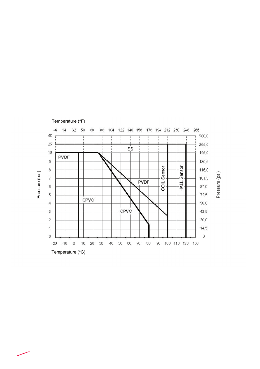
Maximum Operating Pressure / Temperature (25 years lifetime)
• CPVC body:
- 10 bar (145 psi) @ 25°C (77°F)
- 1,5 bar (22 psi) @ 80° C (176°F)
• PVDF body:
- 10 bar (145 psi) @ 25°C (77°F)
- 2,5 bar (36 psi) @ 100°C (212°F)
• SS body:
- 25 bar (363 psi) @ 100°C (212°F)
5
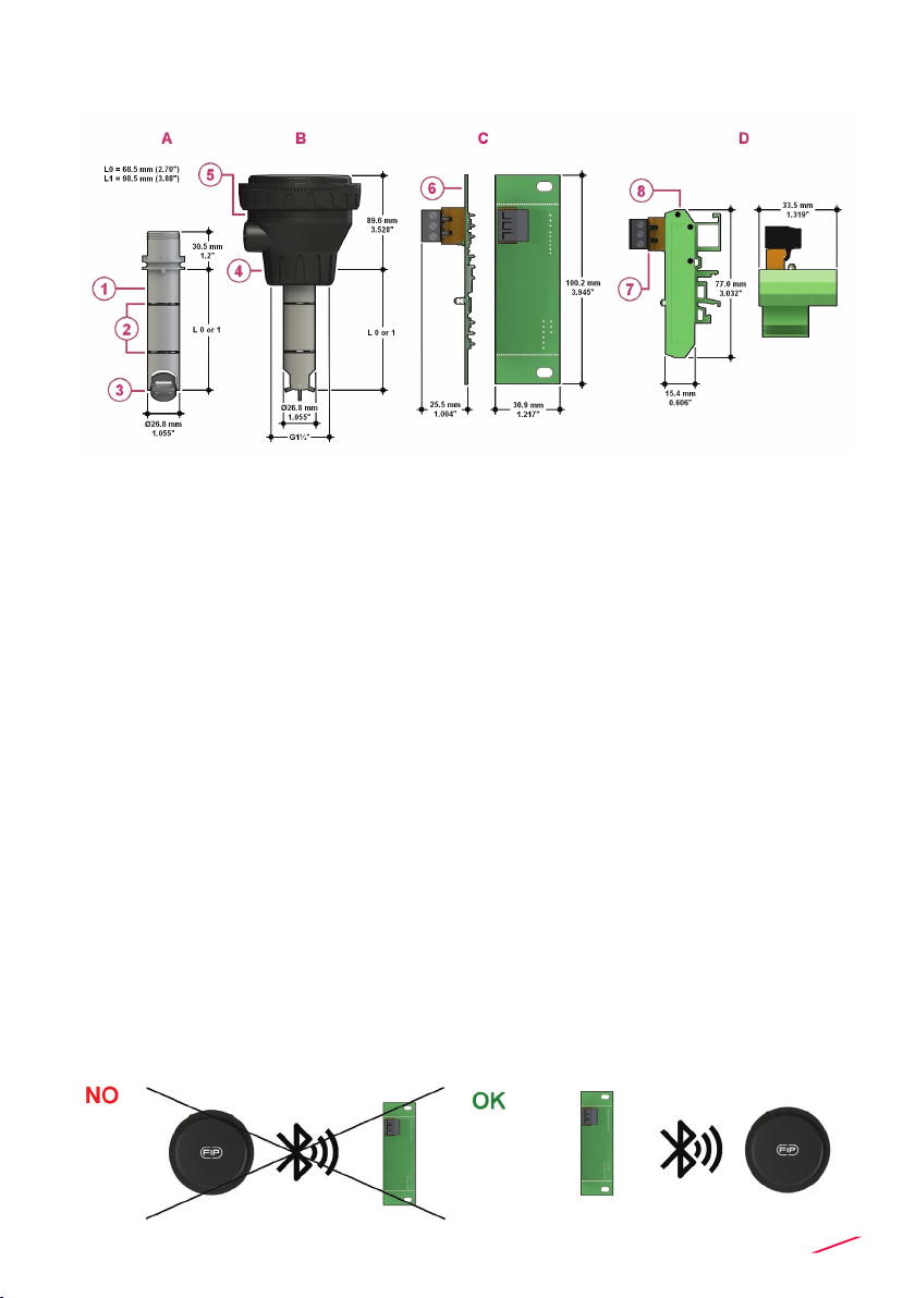
DIMENSIONS
INSTALLATION
System Location
• Nominal distance: 100m (maximum, open eld)
• Operating distance is reduced by following elements:
- tank with liquid
- concrete walls
- re doors
- metal doors
- metal panels
• Optimal installation conditions:
- indoor ambient
- the receiver must face the transmitter. To identify the proper position please
refer to the FIP mark on the box cap. Receiver must face the left side of FIP
mark (see the image below)
ASensor body
BF3.00.W Paddlewheel Flow transmitter
CReceiver PCB
DReceiver + DIN bar adapter
1Sensor body PVCC, PVDF, 316L SS
2O-Ring (EPDM or FPM)
3Halar Rotor, Ceramic shaft & bearings
for PVDF and PVC-C version and 316 SS
shaft for metal version
4 ABS cap for installation into ttings
5Electronic box
6PCB
7Connectors
8DIN bar case adapter
6
• To verify the correct F3.00.W system location, use the following procedures:
- Insert a charged battery into the trasmitter.
- To connect with FLS monitor:
▪ Follow the rst calibration procedure on the monitor.
▪ Select the option wireless sensor F3.00.W.
▪ Check the signal strength with the specic function “SIGNAL INTENSITY”
in the calibration menu. The system will return one of the following
intensity level:
LOW > the level of signal is low; any possible external factor can easily
degrade it. It is recommended to reconsider the system location.
MEDIUM > the level of signal is adequate; it is recommended to avoid
upsetting the installation condition (e.g. avoid adding structural elements
as concrete walls between transmitter and receiver)
HIGH > the level of signal is good and safe.
- To connect with PLC:
▪ Check the signal strength:
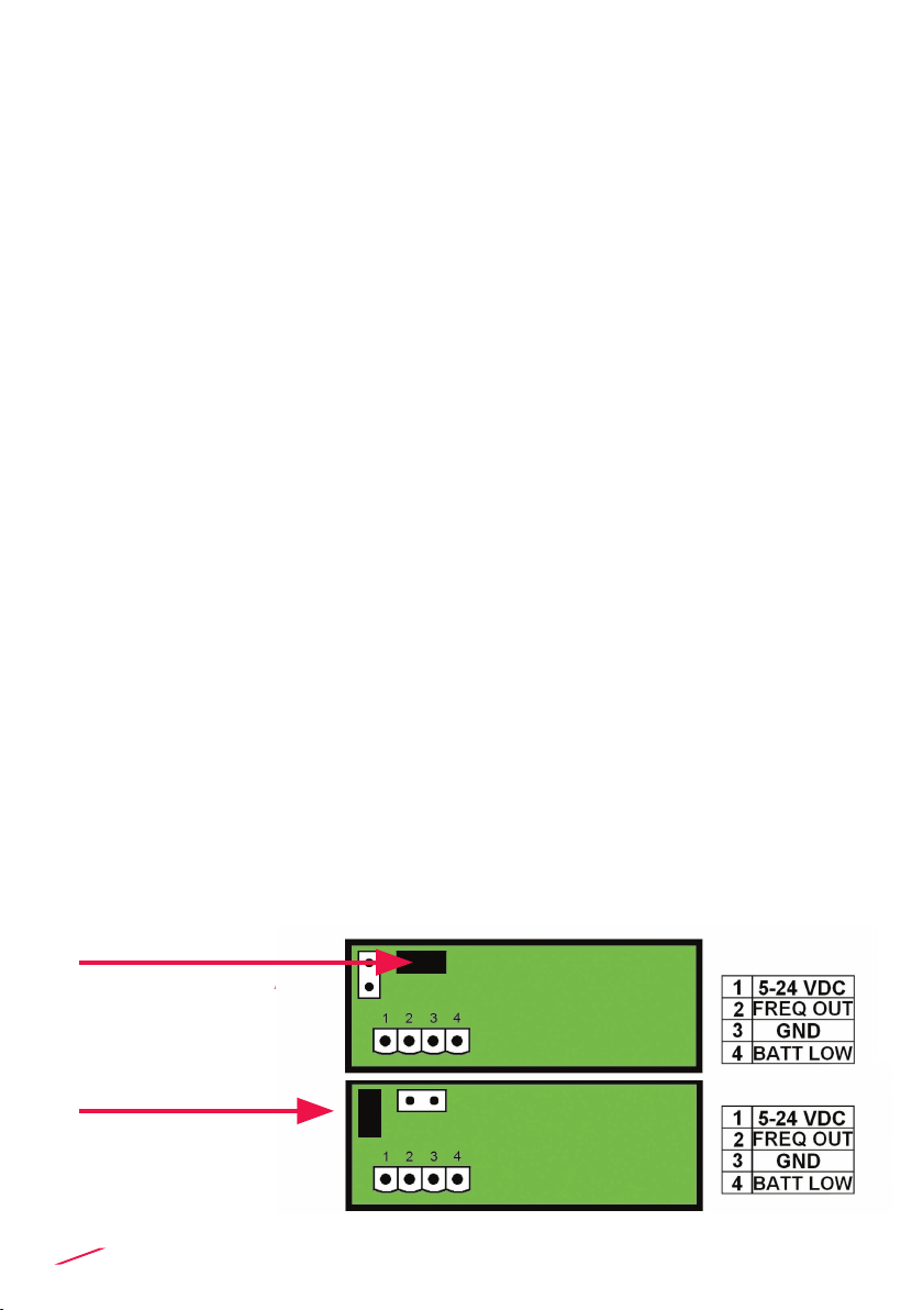
> Put the JUMPER in the “SIGNAL TEST” position as indicated
in the image below.
> Connect with digital input, as indicated in the section
“POWER WIRING DIAGRAM”.
> Set the PLC considering the following correspondence between
the output frequency and the signal intensity:
100Hz > the level of signal is low; any possible external factor
can easily degrade it.
It is recommended to reconsider the system location
200Hz > the level of signal is adequate; it is recommended to avoid
upsetting the installation condition (e.g. avoid adding structural
elements as concrete walls between transmitter and receiver)
300Hz > the level of signal is good and safe.
- Make sure to put the JUMPER in the position “PARK” to make the
system operative. Please refer to image below.
JUMPER IN “SIGNAL
TEST” POSITION
JUMPER IN “PARK”
POSITION
7
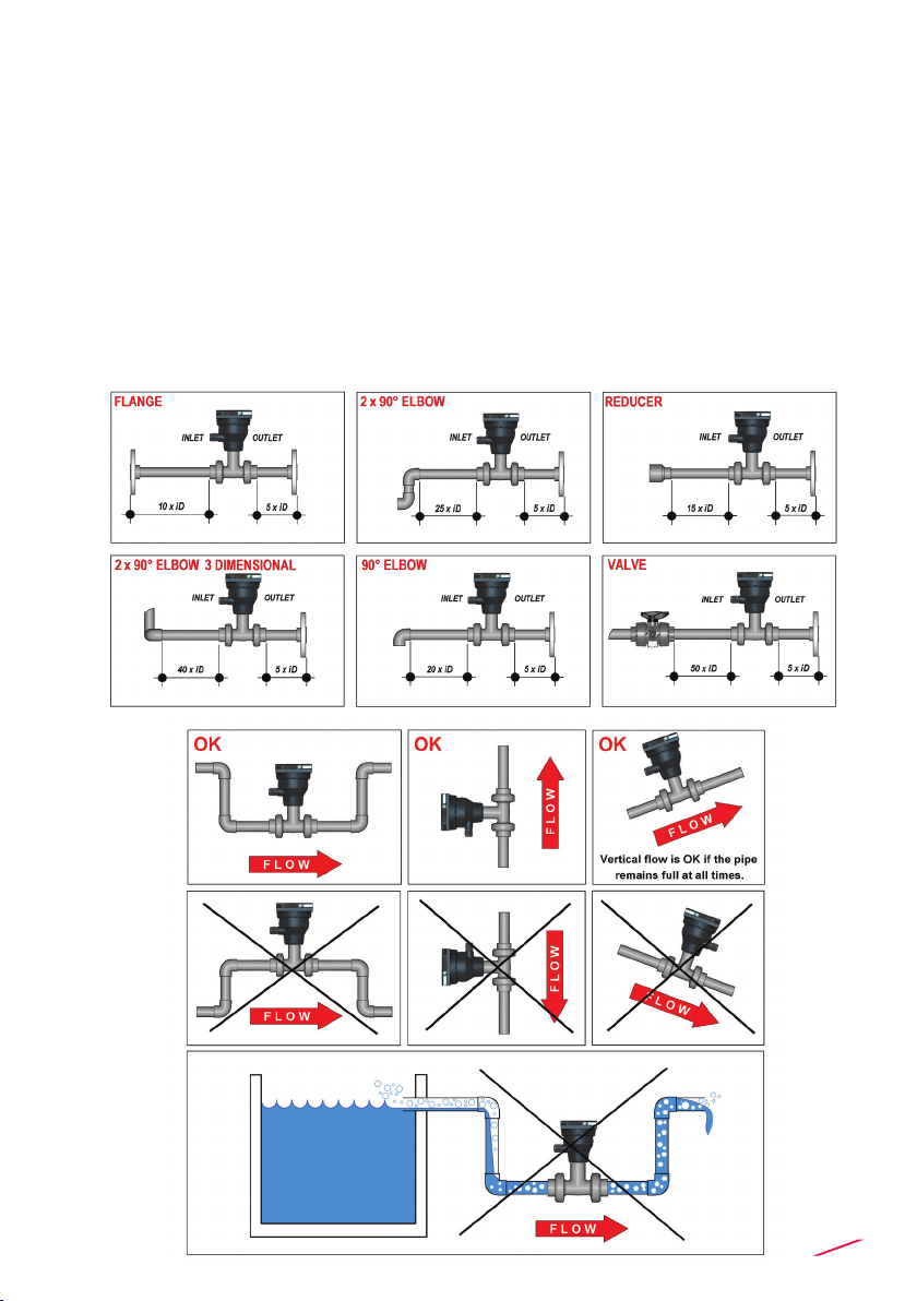
Fig.1
Fig.2
Fig.3
Fig.4
Pipe Location
• The six most common installation congurations shown in g. 1 help in selecting
the best location in the pipeline for paddlewheel ow sensor as well for magmeter
ow sensor.
• The three congurations in g. 2 ensure that the pipe is always full: for a correct
measurement the sensor can NOT be exposed to air bubbles at any time.
• The three installations in Fig. 3 should be avoided unless you are absolutely sure
the sensor is not exposed to air bubbles.
• In gravity-ow systems the connection to the tank must be designed so the
level does not drop below the outlet: this to avoid pipe to draw air in from the tank
causing a inaccurate measurement of sensor (see Fig. 4).
• For more information, please refer to EN ISO 5167-1.
• Always maximize distance between ow sensors and pumps.

8
Mounting position
Measuring part of sensor (rotor for paddlewheel and pins for magmeter)
should be positioned at 12% of ID where, basing on insertion theory, average
velocity can be measured.
The reading accuracy of insertion ow sensors can be aected by:
• air bubbles;
• sediments;
• friction between shaft and bearings.
In a horizontal pipe runs, the mounting position to get the best performances is
at a 45° angle (Fig. 3) to avoid air bubbles as well sediments. Vertical position
(Fig. 2) can be chosen in case air bubbles are not present. Do not mount the
sensor on the bottom of the pipe (Fig. 1) if sediments are likely. Do not mount
paddlewheel at 90° otherwise friction can aect measurement.
Installation in a vertical pipe runs can be done xing any orientation.
Upward ow is preferred to ensure full pipe.
Process connection
1. Lubricate the sensor O-rings
with a silicone lubricant. Do
not use any petroleum based
lubricant that may damage the
O-rings.
2. Lower the sensor into the tting
making sure the alignment tab is
seated in the tting notch.
3. Hand tighten the sensor cap.
Do not use any tool otherwise
cap and/or tting threads may be
damaged.
9
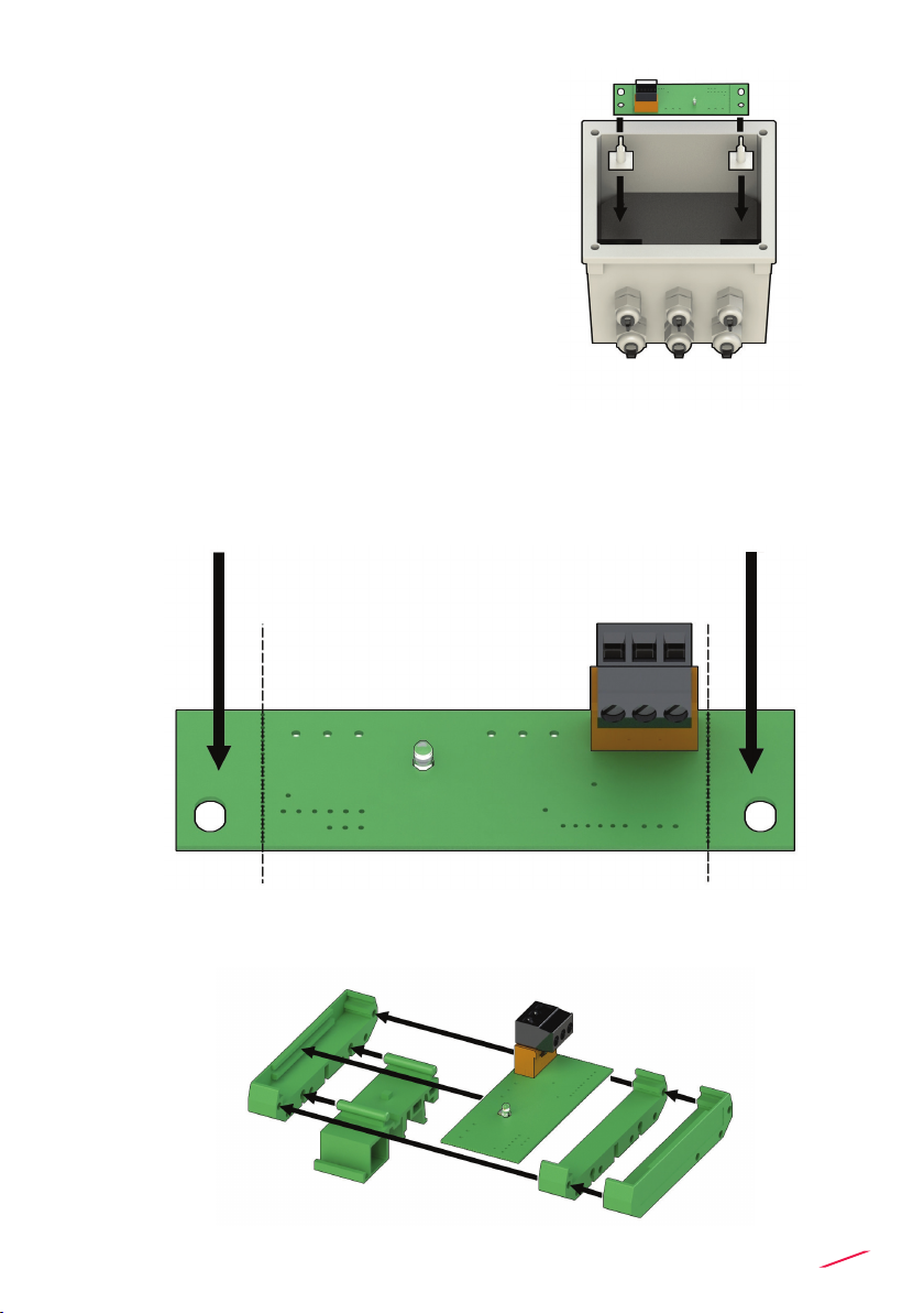
Receiver installation
Wall mounting W1-W2
1. Clean the surface where the PCB must be
glued
3. Remove the protective lm from the PCB
support already mounted
4. Install the PCB according to the picture.
Installation on the upper part of the box is
reccommended.
DIN bar adapter
1. Remove the external ns following the dotted line indication on the receiver
PCB see gure 1
2. assemble the receiver PCB following the sequence in the gure 2
Fig.1
REMOVABLE PART REMOVABLE PART
CUTTING LINECUTTING LINE
Fig.2

10
WIRING
General recommendation
Always ensure the power supply is switched o before working on the device.
Make wiring connections according to wiring diagrams.
• Terminals accept 26 to 12 AWG (0.08 to 2.5 mm2)
• Strip around 10 mm (0.4”) of insulation from the wire tips and tin bare ends to
avoid fraying.
• Ferrules are suggested when connecting more than one wire to a single
terminal.
• Remove the upper part of the terminals for an easy cabling.
• Insert wire tip or ferrule completely into the terminal and x with the screw
until nger tight.
• Do not route the sensor or DC power in conduit containing AC power wiring.
Electrical noise may interfere with sensor signal.
• Routing the sensor cable in grounded metal conduit can help prevent
electrical noise and mechanical damage.
• Seal the cable entry points to prevent moisture damage.
REAR TERMINAL VIEW
11
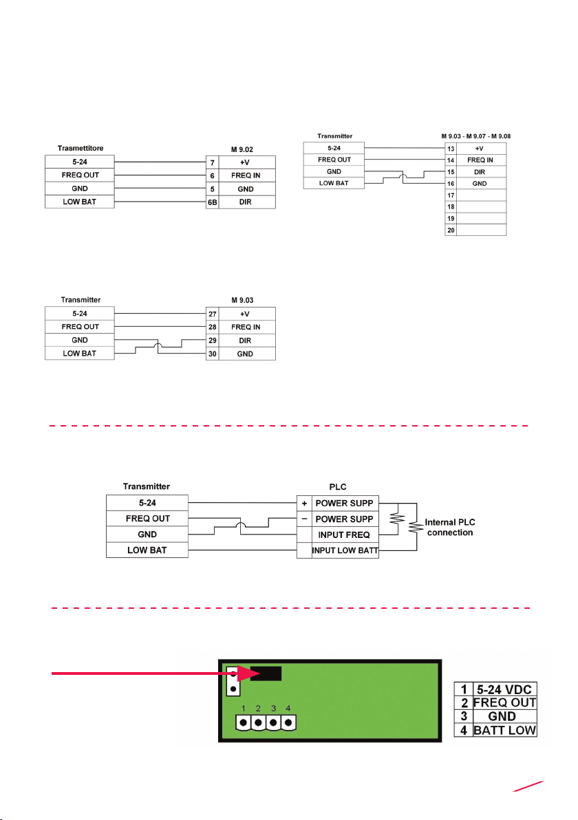
POWER WIRING DIAGRAM
Connection to
FLS M9.02 monitor
Connection to a PLC
Connection to FLS M9.03, M9.07
and M9.08 monitors
Connection for signal intensity function
JUMPER IN
“SIGNAL TEST”
POSITION
*
*
Please note: on M9.02, M9.03, M9.07 and M9.08 DIR is the connection for low battery alarm.
Connection to
FLS M9.03 monitor sensor input 1

12
INSTALLATION FITTINGS
Type Description
Plastic Tees
• Size: d20 to d50 (0.5” to 1.5”)
• Materials: PVC, C-PVC, PP, PVDF
PVC-U Clamp Saddles
• Size: d63 to d225 (2” to 8”)
• Insert Materials: C-PVC, PVDF
316L SS Tees • Size: d63 to d315
• Materials: PVC, C-PVC, PP, PE
Metal Strap-on Saddles
• Size: DN80 to DN450
• Insert Material: C-PVC
• Special order for other sizes
316L SS Weld-on Adapters • Size: d50 to d600 (1.5” to 24”)

13
K-FACTOR TABLES
K-Factor is the number of pulses which a sensor produces for one liter of
measured uid. Here below all K-Factors for water at room temperature are
listed.
K-Factor values can depend on the installation conditions. K-Factor has to
divide the frequency generated by F3.00 in order to achieve the ow rate (l/s).
Please contact your dealer for K-Factor values not included in the table.
Installation on PVC pipes
ISO Metric Clamp Saddles for ISO SDR 21 pipes
(PN10 up to d 90mm, PN12,5 from d 110mm)
Part No. DN d K-Factor
SVIC063BVC 50 63 21,69
SVIC075BVC 65 75 14,98
SVIC090BVC 80 90 9,88
SVIC110BVC 100 110 6,06
SVIC125BVC 110 125 4,59
SVIC140BVC 125 140 3,59
SVIC160BVC 150 160 2,69
SVIC200BVC 180 200 1,65
SVIC225BVC 200 225 1,28
SVIC063DVC 50 63 21,69
SVIC075DVC 65 75 14,98
SVIC090DVC 80 90 9,88
SVIC110DVC 100 110 6,06
SVIC125DVC 110 125 4,59
SVIC140DVC 125 140 3,59
SVIC160DVC 150 160 2,69
SVIC200DVC 180 200 1,65
SVIC225DVC 200 225 1,28
SMIC250IVC 225 250 1,01
SMIC280IVC 250 280 0,79
SMIC315IVC 280 315 0,61
ISO Metric PVC Tee Fittings for ISO SDR
21 pipes (female ends for solvent welding)
Part No. DN d K-Factor
TFIV20B 15 20 235,45
TFIV25B 20 25 142,46
TFIV32B 25 32 91,53
TFIV40B 32 40 51,57
TFIV50B 40 50 42,89
TFIV20D 15 20 235,45
TFIV25D 20 25 142,46
TFIV32D 25 32 91,53
TFIV40D 32 40 51,57
TFIV50D 40 50 42,89
BSP Female Threaded PVC Tee Fittings
for BS PN12 pipes
(parallel threaded female ends)
Part No. DN R K-Factor
TFFV20B 15 1/2" 235,45
TFFV25B 20 3/4" 142,46
TFFV32B 25 1" 91,53
TFFV40B 32 1" 1/4 51,57
TFFV50B 40 1" 1/2 42,89
TFFV20D 15 1/2" 235,45
TFFV25D 20 3/4" 142,46
TFFV32D 25 1" 91,53
TFFV40D 32 1" 1/4 51,57
TFFV50D 40 1" 1/2 42,89
BS Solvent Welding PVC Tee Fittings
for BS PN12 pipes
(female ends for solvent welding)
Part No. DN d K-Factor
TFLV20B 15 1/2" 235,45
TFLV25B 20 3/4" 142,46
TFLV32B 25 1" 91,53
TFLV40B 32 1" 1/4 51,57
TFLV50B 40 1" 1/2 42,89
TFLV20D 15 1/2" 235,45
TFLV25D 20 3/4" 142,46
TFLV32D 25 1" 91,53
TFLV40D 32 1" 1/4 51,57
TFLV50D 40 1" 1/2 42,89
"

14
BS Clamp Saddles for BS PN12 pipes
Part No. DN d K-Factor
SVLC2.0BVM 50 2" 24,10
SVLC3.0BVM 80 3" 10,29
SVLC4.0BVM 100 4" 5,72
SVLC6.0BVM 150 6" 2,48
SVLC8.0BVM 200 8" 1,34
SVLC2.0DVM 50 2" 24,10
SVLC3.0DVM 80 3" 10,29
SVLC4.0DVM 100 4" 5,72
SVLC6.0DVM 150 6" 2,48
SVLC8.0DVM 200 8" 1,34
ASTM SCH. 80 Clamp Saddles
for ASTM SCH. 80 pipes
Part No. SIZE d K-Factor
SVAC2.0BVM 2.00" -29,74
SVAC2.5BVM 2.50" - 20,25
SVAC3.0BVM 3.00" - 12,36
SVAC4.0BVM 4.00" - 6,47
SVAC5.0BVM 5.00" - 4,00
SVAC6.0BVM 6.00" - 2,68
SVAC8.0BVM 8.00" - 1,46
SVAC2.0DVM 2.00" -29,74
SVAC2.5DVM 2.50" - 20,25
SVAC3.0DVM 3.00" - 12,36
SVAC4.0DVM 4.00" - 6,47
SVAC5.0DVM 5.00" - 4,00
SVAC6.0DVM 6.00" - 2,68
SVAC8.0DVM 8.00" - 1,46
NPT Female Threaded PVC Tee Fittings
for ASTM SCH. 80 pipes
(NPT threaded female ends)
Part No. SIZE R K-Factor
TFNV20B 0.50" 1/2" 235,45
TFNV25B 0.75" 3/4" 142,46
TFNV32B 1.00" 1" 91,53
TFNV40B 1.25" 1" 1/4 51,57
TFNV50B 1.50" 1" 1/2 42,89
TFNV20D 0.50" 1/2" 235,45
TFNV25D 0.75" 3/4" 142,46
TFNV32D 1.00" 1" 91,53
TFNV40D 1.25" 1" 1/4 51,57
TFNV50D 1.50" 1" 1/2 42,89
ASTM SCH. 80 PVC Tee Fittings
for ASTM SCH. 80 pipes
(female ends for solvent welding)
Part No. SIZE d K-Factor
TFAV20B 0.50" 1/2" 235,45
TFAV25B 0.75" 3/4" 142,46
TFAV32B 1.00" 1" 91,53
TFAV40B 1.25" 1" 1/4 51,57
TFAV50B 1.50" 1" 1/2 42,89
TFAV20D 0.50" 1/2" 235,45
TFAV25D 0.75" 3/4" 142,46
TFAV32D 1.00" 1" 91,53
TFAV40D 1.25" 1" 1/4 51,57
TFAV50D 1.50" 1" 1/2 42,89

15
Installation on C-PVC pipes
Installation on PP pipes
ISO Metric CPVC Tee Fitings for ISO SDR 21
pipes (female ends for solvent welding)
Part No. DN d K-Factor
TFIC20B 15 20 235,45
TFIC25B 20 25 142,46
TFIC32B 25 32 91,53
TFIC40B 32 40 51,57
TFIC50B 40 50 42,89
TFIC20D 15 20 235,45
TFIC25D 20 25 142,46
TFIC32D 25 32 91,53
TFIC40D 32 40 51,57
TFIC50D 40 50 42,89
ISO Metric PP Tee Fittings for ISO SDR 11 pipes
(female ends for socket welding)
Part No. DN d K-Factor
TFIM20B 15 20 212,17
TFIM25B 20 25 135,32
TFIM32B 25 32 89,36
TFIM40B 32 40 48,94
TFIM50B 40 50 42,10
TFIM20D 15 20 212,17
TFIM25D 20 25 135,32
TFIM32D 25 32 89,36
TFIM40D 32 40 48,94
TFIM50D 40 50 42,10
BSP Female Threaded PP Tee Fittings
for BS pipes (parallel threaded female ends)
Part No. DN R K-Factor
TFFM20B 15 1/2" 212,17
TFFM25B 20 3/4" 135,32
TFFM32B 25 1" 89,36
TFFM40B 32 1" 1/4 48,94
TFFM50B 40 1" 1/2 42,10
TFFM20D 15 1/2" 212,17
TFFM25D 20 3/4" 135,32
TFFM32D 25 1" 89,36
TFFM40D 32 1" 1/4 48,94
TFFM50D 40 1" 1/2 42,10
ISO Clamp Saddles for ISO SDR 21 pipes
Part No. DN d K-Factor
SVIC063BVC 50 63 21,69
SVIC075BVC 65 75 14,98
SVIC090BVC 80 90 9,88
SVIC110BVC 100 110 6,06
SVIC125BVC 110 125 4,59
SVIC140BVC 125 140 3,59
SVIC160BVC 150 160 2,69
SVIC200BVC 180 200 1,65
SVIC225BVC 200 225 1,28
SVIC063DVC 50 63 21,69
SVIC075DVC 65 75 14,98
SVIC090DVC 80 90 9,88
SVIC110DVC 100 110 6,06
SVIC125DVC 110 125 4,59
SVIC140DVC 125 140 3,59
SVIC160DVC 150 160 2,69
SVIC200DVC 180 200 1,65
SVIC225DVC 200 225 1,28
SMIC250IVC 225 250 1,01
SMIC280IVC 250 280 0,79
SMIC315IVC 280 315 0,61

16
NPT Female Threaded PP Tee Fittings
for ASTM SCH.80 pipes
(NPT threaded female ends)
Part No. DN d K-Factor
TFNM20B 0.50" 1/2" 212,17
TFNM25B 0.75" 3/4" 135,32
TFNM32B 1.00" 1" 89,36
TFNM40B 1.25" 1" 1/4 48,94
TFNM50B 1.50" 1" 1/2 42,10
TFNM20D 0.50" 1/2" 212,17
TFNM25D 0.75" 3/4" 135,32
TFNM32D 1.00" 1" 89,36
TFNM40D 1.25" 1" 1/4 48,94
TFNM50D 1.50" 1" 1/2 42,10
ISO Clamp Saddles for ISO SDR 21 pipes
Part No. DN d K-Factor
SVIC063BME 50 63 27,50
SVIC075BME 65 75 18,56
SVIC090BME 80 90 12,44
SVIC110BME 100 110 7,59
SVIC125BME 110 125 5,77
SVIC140BME 125 140 4,49
SVIC160BME 150 160 3,38
SVIC200BME 180 200 2,07
SVIC225BME 200 225 1,60
SVIC063DME 50 63 27,50
SVIC075DME 65 75 18,56
SVIC090DME 80 90 12,44
SVIC110DME 100 110 7,59
SVIC125DME 110 125 5,77
SVIC140DME 125 140 4,49
SVIC160DME 150 160 3,38
SVIC200DME 180 200 2,07
SVIC225DME 200 225 1,60
SMIC250IME 225 250 1,27
SMIC280IME 250 280 0,99
SMIC315IME 280 315 0,77
ASTM SCH. 80 Clamp Saddles
for ASTM SCH. 80 pipes
Part No. SIZE d K-Factor
SVAC2.0BME 2.00" -29,83
SVAC2.5BME 2.50" - 20,37
SVAC3.0BME 3.00" - 12,36
SVAC4.0BME 4.00" - 6,47
SVAC5.0BME 5.00" -3,92
SVAC6.0BME 6.00" - 1,53
SVAC8.0BME 8.00" - 1,44
SVAC2.0DME 2.00" -29,83
SVAC2.5DME 2.50" - 20,37
SVAC3.0DME 3.00" - 12,36
SVAC4.0DME 4.00" - 6,47
SVAC5.0DME 5.00" -3,92
SVAC6.0DME 6.00" - 1,53
SVAC8.0DME 8.00" - 1,44

17
Installation on PVDF pipes
Installation on PE pipes
ISO Metric PVDF Tee Fittings for ISO SDR 33
pipes (female ends for socket welding)
Part No. DN d K-Factor
TFIF20B 15 20 225,06
TFIF25B 20 25 139,38
TFIF32B 25 32 94,66
TFIF40B 32 40 51,37
TFIF50B 40 50 43,07
TFIF20D 15 20 225,06
TFIF25D 20 25 139,38
TFIF32D 25 32 94,66
TFIF40D 32 40 51,37
TFIF50D 40 50 43,07
ISO Metric PVC Tee Fittings
for PE SDR 11 pipes (PE end connectors
for electrofusion or butt welding)
Part No. DN d K-Factor
TFIV20BE 15 20 193,70
TFIV25BE 20 25 134,07
TFIV32BE 25 32 85,29
TFIV40BE 32 40 48,68
TFIV50BE 40 50 41,68
TFIV20DE 15 20 193,70
TFIV25DE 20 25 134,07
TFIV32DE 25 32 85,29
TFIV40DE 32 40 48,68
TFIV50DE 40 50 41,68
ISO Clamp Saddles for ISO SDR 33 pipes
Part No. DN d K-Factor
SVIF063BF 50 63 20,58
SVIF 075BF 65 75 14,09
SVIF 090BF 80 90 9,29
SVIF 110BF 100 110 5,69
SVIF 125BF 110 125 4,31
SVIF 140BF 125 140 3,36
SVIF 160BF 150 160 2,52
SVIF 200BF 180 200 1,55
SVIF 225BF 200 225 1,20
SVIF 063DF 50 63 20,58
SVIF 075DF 65 75 14,09
SVIF 090DF 80 90 9,29
SVIF 110DF 100 110 5,69
SVIF 125DF 110 125 4,31
SVIF 140DF 125 140 3,36
SVIF 160DF 150 160 2,52
SVIF 200DF 180 200 1,55
SVIF 225DF 200 225 1,20
ISO Clamp Saddles for PE SDR 11 pipes
Part No. DN d K-Factor
SVIC063BME 50 63 27,39
SVIC075BME 65 75 18,75
SVIC090BME 80 90 12,41
SVIC110BME 100 110 7,57
SVIC125BME 110 125 5,76
SVIC140BME 125 140 4,49
SVIC160BME 150 160 3,37
SVIC200BME 180 200 2,02
SVIC225BME 200 225 1,60
SVIC063DME 50 63 27,39
SVIC075DME 65 75 18,75
SVIC090DME 80 90 12,41
SCIC110DME 100 110 7,57
SVIC125DME 110 125 5,76
SVIC140DME 125 140 4,49
SVIC160DME 150 160 3,37
SVIC200DME 180 200 2,02
SVIC225DME 200 225 1,60
SMIC250IME 225 250 1,27
SMIC280IME 250 280 0,99
SMIC315IME 280 315 0,77

18
Installation on Metal pipes
316L SS Threaded Tees
(BSP Female Threads)
Part No. DN R K-Factor
TFFX20 15 1/2" -
TFFX25 20 3/4 157,06
TFFX32 25 1" 92,84
TFFX40 32 1" 1/4 51,52
Metal Strap-on Saddles
mounted on Cast Iron pipes
Part No. DN K-Factor
SZIC080I 80 10,22
SZIC100I 100 6,01
SZIC125I 125 3,64
SZIC150I 150 2,46
SZIC200I 200 1,28
SZIC250I 250 0,79
SZIC300I 300 0,53
SZIC350I 350 0,4
SZIC400I 400 0,31
SZIC450I 450 0,24
Metal Strap-on Saddles
mounted on Other Metal pipes
Part No. DN K-Factor
SZIC080I 80 9,61
SZIC100I 100 5,22
SZIC125I 125 3,31
SZIC150I 150 2,22
SZIC200I 200 1,23
SZIC250I 250 0,75
SZIC300I 300 0,52
SZIC350I 350 0,43
SZIC400I 400 0,32
SZIC450I 450 -
316L SS Weld-on Adapters
mounted on Other Metal pipes
Part No. DN K-Factor
WAIXL0 40 36,17
WAIXL0 50 23,71
WAIXL0 60 -
WAIXL0 65 13,93
WAIXL0 80 9,61
WAIXL0 100 5,22
WAIXL0 110 -
WAIXL0 125 3,31
WAIXL0 150 2,22
WAIXL0 175 -
WAIXL0 200 1,23
WAIXL1 225 0.75
WAIXL1 250 0,52
WAIXL1 300 0,43
WAIXL1 350 0,32
WAIXL1 400 -
WAIXL1 450 0,20
WAIXL1 500 -
WAIXL1 600 0,14
316L SS Weld-on Adapters
mounted on Cast Iron pipes
Part No. DN K-Factor
WAIXL0 40 -
WAIXL0 50 -
WAIXL0 60 19,78
WAIXL0 65 -
WAIXL0 80 10,22
WAIXL0 100 6,01
WAIXL0 110 -
WAIXL0 125 3,64
WAIXL0 150 2,46
WAIXL0 175 -
WAIXL0 200 1,28
WAIXL1 225 -
WAIXL1 250 0,79
WAIXL1 300 0,53
WAIXL1 350 0,40
WAIXL1 400 0,31
WAIXL1 450 0,24
WAIXL1 500 0,20
WAIXL1 600 0,14

19
Correction formula for K-Factor calculation according to real internal
diameter:
K-Factor_NEW = (K-Factor x ID²) / ID_NEW²
ID = Value in the table for the internal diameter (in mm)
ID_NEW = New value for the real internal diameter (always in mm)
K-Factor = Value in the table
K-Factor_NEW = New K-Factor value for the specied internal diameter
Example:
Nominal Pipe Size (DN) = 100 mm
New Internal Diameter = 104 mm
Forumla: K-Factor_NEW = (51.02 x 100²) / 104² = 20,52
ORDERING DATA
Part No. Version Power
supply Length Main wetted
materials Enclosure Flow Rate
Range
Weight
(gr.)
F3.00.W.13 Hall See electrical
data section L0 CPVC/EPDM IP65 0.15 to 8 m/s
(0.5 to 25 ft./s.) 750
F3.00.W.14 Hall See electrical
data section L0 CPVC/FPM IP65 0.15 to 8 m/s
(0.5 to 25 ft./s.) 750
F3.00.W.15 Hall See electrical
data section L1 CPVC/EPDM IP65 0.15 to 8 m/s
(0.5 to 25 ft./s.) 800
F3.00.W.16 Hall See electrical
data section L1 CPVC/FPM IP65 0.15 to 8 m/s
(0.5 to 25 ft./s.) 800
F3.00.W.17 Hall See electrical
data section L0 PVDF/EPDM IP65 0.15 to 8 m/s
(0.5 to 25 ft./s.) 750
F3.00.W.18 Hall See electrical
data section L0 PVDF/FPM IP65 0.15 to 8 m/s
(0.5 to 25 ft./s.) 750
F3.00.W.19 Hall See electrical
data section L1 PVDF/EPDM IP65 0.15 to 8 m/s
(0.5 to 25 ft./s.) 800
F3.00.W.20 Hall See electrical
data section L1 PVDF/FPM IP65 0.15 to 8 m/s
(0.5 to 25 ft./s.) 800
F3.00.W.21 Hall See electrical
data section L0 316SS/EPDM IP65 0.15 to 8 m/s
(0.5 to 25 ft./s.) 950
F3.00.W.22 Hall See electrical
data section L0 316SS/FPM IP65 0.15 to 8 m/s
(0.5 to 25 ft./s.) 950
F3.00.W.23 Hall See electrical
data section L1 316SS/EPDM IP65 0.15 to 8 m/s
(0.5 to 25 ft./s.) 1000
F3.00.W.24 Hall See electrical
data section L1 316SS/FPM IP65 0.15 to 8 m/s
(0.5 to 25 ft./s.) 1000

FIP - Formatura Iniezione Polimeri S.p.A.
Loc. Pian di Parata
16015 Casella
Genova - Italy
Tel. +39 010 96211
Fax +39 010 9621209
www.flsnet.it
I2445 - IMF300WE - REV-01 05/2020
Table of contents
Other FIP Accessories manuals


