FIP FLS F6.60 User manual

1
FLS F6.60
FLOW MAGMETER
SAFETY INSTRUCTIONS
General Statements
• Do not install and service the product without following the Instruction
Manual.
• This item is designed to be connected to other instruments which can be
hazardous if used improperly. Read and follow all associated instrument
manuals before using with it.
• Product installation and wiring connections should only be performed by
qualied staff.
• Do not modify product construction.
Installation and Commissioning Statements
• Remove power to the instrument before wiring input and output connections.
• Do not exceed maximum specications using the instrument.
• To clean the unit, use only chemical compatible products.

2
PACKING LIST
Please verify that the product is complete and without any damage. The
following items must be included:
• F6.60 Flow Magmeter
• Instruction Manual for F6.60 Flow Magmeter
• USB pen drive with interface software
• USB cable for instrument/PC interface
DESCRIPTION
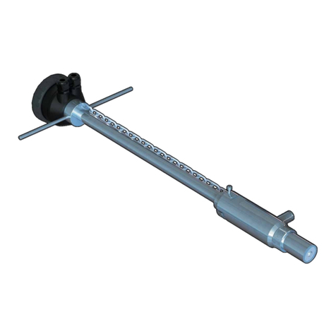
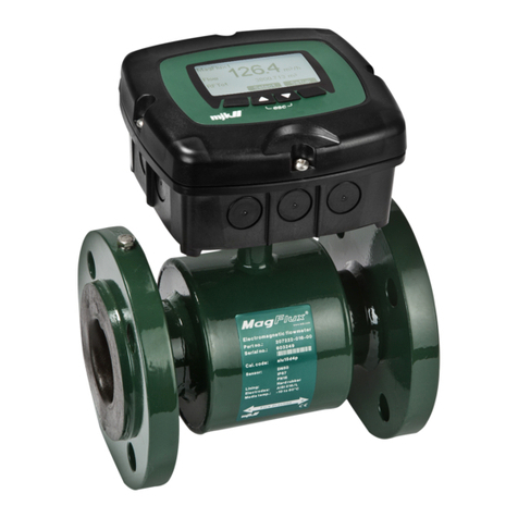
The new FLS F6.60 is a ow meter without moving mechanical parts which
can be applied for the measurement of dirty liquids so long as they are
conductive and homogeneous.
The F6.60 can provide three different options: frequency output to
be connected to FLS ow monitors, 4-20 mA output for long distance
transmission and PLC connection and the new volume pulse output freely
settable.
F6.60 Insertion Magmeter is provided with an USB interface and a dedicated
software (freely downloadable from FLS web site) which allows to easily set
by a PC all parameters according to specic installation requirements (as full
scale and cut off).
The specic design allows an accurate ow measurement over a wide
dynamic range in pipe sizes from DN15 (0.5”) to DN600 (24”).

3
TECHNICAL DATA
General
• Pipe Size Range: DN15 to DN600 (0.5” to 24”)
• Max Flow Rate Range:
from 0.05 to 8 m/s (0.15 to 26.24 ft/s)
• Full Scale: 8 m/s (26.24 ft/s)
• Linearity: ± 1% of reading + 1,0 cm/s
• Repeatability: ± 0.5% of reading
• Enclosure: IP65
• Materials:
- case: PC/ABS
- gasket: EPDM
• Wetted Materials:
- sensor body: 316L SS/PVDF; 316L SS/ PEEK; CuNi alloy/PVDF
- o-rings: EPDM or FPM
- electrodes: 316L SS or CuNi alloy
Electrical
• Power Supply:
- 12 to 24 VDC ± 10% regulated (reverse polarity and short circuit protected)
- maximum current: consumption: 250 mA
- protective earth: < 10 Ω
• Current output:
- 4-20 mA, isolated
- max. loop impedance: 800 Ω @ 24 VDC - 250 Ω @ 12 VDC
- positive or negative ow indication
• Solid State Relay output:
- user selectable as MIN alarm, MAX alarm, Volumetric, Pulse Out, Window
alarm, Off
- optically isolated, 50 mA MAX sink, 24 VDC MAX pull-up voltage
- max pulse/min: 300
- hysteresis: User selectable
• Open Collector output (Frequency):
- Ttype: Open Collector NPN
- frequency: 0 – 800 Hz
- max. Pull-up Voltage: 24 VDC
- max. Current: 50 mA, current limited
- compatible with FLOWX3 M9.02, M9.03, M9.50
• Open Collector output (Direction):
- type: Open Collector NPN
- max. Pull-up Voltage: 24 VDC
- max. Current: 50mA, current limited
- ow direction:
0 VDC arrow-wise
+ VDC anti arrow-wise

4
Enviromental
• Storage Temperature: -30°C to +80°C (-22°F to
176°F)
• Ambient Temperature: -20°C to +70°C (-4°F to
158°F)
• Relative Humidity:0 to 95% (non-condensing)
• Fluid conditions:
- homogeneous liquids, pastes or slurries, also with solid content
- min electrical conductivity: 20 μS
- temperature:
PVDF bottom version: -10 °C to +60 °C (14 °F to 140 °F)
PEEK bottom version: -10 °C +150 °C (14 °F to 302 °F)
• Max. operating pressure:
- 16 bar @ 25°C (232 psi @ 77°F)
- 8.6 bar @ 60°C (124 psi @ 140°F)
Standards & Approvals
• Manufactured under ISO 9001
• Manufactured under ISO 14001
• CE
• RoHS Compliant
• GOST R

5
DIMENSIONS
A Sensor body
B F6.60 Magmeter
1 O-Ring (EPDM or FPM)
2 Sensor body (316L SS or CuNi)
3 Isolation Plate (PVDF or PEEK)
4Electrodes (316L SS or CuNi)
5 Cable Gland
6ABS cap for installation into ttings
7 Electronic box
INSTALLATION
Pipe Location
• The six most common installation congurations shown in g. 1 help in
selecting the best location in the pipeline for paddlewheel ow sensor as well
for magmeter ow sensor.
• The three congurations in g. 2 ensure that the pipe is always full: for a
correct measurement the sensor can NOT be exposed to air bubbles at any
time.
• The three installations in Fig. 3 should be avoided unless you are absolutely
sure the sensor is not exposed to air bubbles.
• In gravity-ow systems the connection to the tank must be designed so the
level does not drop below the outlet: this to avoid pipe to draw air in from the
tank causing a inaccurate measurement of sensor (see Fig. 4).
• For more information, please refer to EN ISO 5167-1.
• Always maximize distance between ow sensors and pumps.

6
Fig.1
Fig.2
Fig.3
Fig.4

7
Process connection
1. Lubricate the sensor O-rings
with a silicone lubricant. Do
not use any petroleum based
lubricant that may damage the
O-rings.
2. Lower the sensor into the tting
making sure the alignment tab is
seated in the tting notch.
3. Hand tighten the sensor cap.
Do not use any tool otherwise
cap and/or tting threads may be
damaged.
Mounting position
Measuring part of sensor (rotor for paddlewheel and pins for magmeter)
should be positioned at 12% of ID where, basing on insertion theory, average
velocity can be measured.
The reading accuracy of insertion ow sensors can be affected by:
• air bubbles;
• sediments;
• friction between shaft and bearings (only for paddlewheel).
In a horizontal pipe runs, the mounting position to get the best performances is
at a 45° angle (Fig. 3) to avoid air bubbles as well sediments. Vertical position
(Fig. 2) can be chosen in case air bubbles are not present. Do not mount the
sensor on the bottom of the pipe (Fig. 1) if sediments are likely. Do not mount
paddlewheel at 90° otherwise friction can affect measurement.
Installation in a vertical pipe runs can be done xing any orientation.
Upward ow is preferred to ensure full pipe.

8
REAR TERMINAL VIEW
WIRING
General recommendation
Always ensure the power supply is switched off before working on the device.
Make wiring connections according to wiring diagrams.
• Terminals accept 26 to 12 AWG (0.08 to 2.5 mm2)
• Strip around 10 mm (0.4”) of insulation from the wire tips and tin bare ends to
avoid fraying.
• Ferrules are suggested when connecting more than one wire to a single
terminal.
• Remove the upper part of the terminals for an easy cabling.
• Insert wire tip or ferrule completely into the terminal and x with the screw
until nger tight.
• Do not route the sensor, DC power, or 4-20mA cables in conduit containing
AC power wiring. Electrical noise may interfere with sensor signal.
• Routing the sensor cable in grounded metal conduit can help prevent
electrical noise and mechanical damage.
Specic info
Pull the electrical cables through liquid tight connectors.
Use electrical cables with the proper external diameter for the liquid tight
connector.
PG11/PG9: external diameter between 2-7 mm (0.079-0.276”)

9
POWER/LOOP WIRING DIAGRAM
Stand-alone application,
no current loop used
Connection to a PLC/Instrument with ONE separate power supply
or
Connection to a PLC with built-in
power supply (3 wire connection)
Power Supply
12 - 24 VDC
12 - 24 VDC
+ VDC
- VDC
A
+ LOOP
- LOOP
1
2
3
4
Power Supply
Power Supply
Internal PLC
connection
4 - 20mA Loop Input
4 - 20mA Loop Input
PLC Terminals
+ VDC
- VDC
A
+ LOOP
- LOOP
1
2
3
4
Power Supply
12 - 24 VDC
12 - 24 VDC
PLC / Instrument
4 - 20mA Loop Input
4 - 20mA Loop Input
Power Supply
12 - 24 VDC
12 - 24 VDC
PLC / Instrument
4 - 20mA Loop Input
4 - 20mA Loop Input
+ VDC
- VDC
A
A
+ LOOP
- LOOP
1
2
3
4
+ VDC
- VDC
+ LOOP
- LOOP
1
2
3
4
Power Supply
12 - 24 VDC
12 - 24 VDC
PLC / Instrument
4 - 20mA Loop Input
4 - 20mA Loop Input
Power Supply
12 - 24 VDC
12 - 24 VDC
PLC / Instrument
4 - 20mA Loop Input
4 - 20mA Loop Input
+ VDC
- VDC
A
A
+ LOOP
- LOOP
1
2
3
4
+ VDC
- VDC
+ LOOP
- LOOP
1
2
3
4
Connection to a PLC / Instrument with TWO separate power supplies
or
Power Supply
12 - 24 VDC
12 - 24 VDC
Power Supply
12 - 24 VDC
12 - 24 VDC
PLC / Instrument
4 - 20mA Loop Input
4 - 20mA Loop Input
Power Supply
12 - 24 VDC
12 - 24 VDC
Power Supply
12 - 24 VDC
12 - 24 VDC
PLC / Instrument
4 - 20mA Loop Input
4 - 20mA Loop Input
+ VDC
- VDC
A
A
+ LOOP
- LOOP
1
2
3
4
+ VDC
- VDC
+ LOOP
- LOOP
1
2
3
4
Power Supply
12 - 24 VDC
12 - 24 VDC
Power Supply
12 - 24 VDC
12 - 24 VDC
PLC / Instrument
4 - 20mA Loop Input
4 - 20mA Loop Input
Power Supply
12 - 24 VDC
12 - 24 VDC
Power Supply
12 - 24 VDC
12 - 24 VDC
PLC / Instrument
4 - 20mA Loop Input
4 - 20mA Loop Input
+ VDC
- VDC
A
A
+ LOOP
- LOOP
1
2
3
4
+ VDC
- VDC
+ LOOP
- LOOP
1
2
3
4

10
Imax = 50 mA
Internal PLC
connection
COM
N.O.
5
6
PLC
Imax = 50 mA
Power sup.
Power sup.
O.C. IN
O.C. IN
C
SOLID-STATE RELAY WIRING DIAGRAM
Connection to a PLC with NPN input Connection to a PLC with PNP input
COM
N.O.
5
6
PLC
Imax = 50 mA
Power sup.
Power sup.
O.C. IN
O.C. IN
C
Internal PLC
connection
Connection to a PLC / Instrument
digital input with separate Power
Supply
Connection to a PLC / Instrument
digital input for Voltage Free Contacts
(REED)
PLC
DIGITAL INPUT N
DIGITAL INPUT 2
DIGITAL INPUT 1
REF PLC
COM
Imax
N.O.
6
5
10 Kohm
COM
N.O.
C
6
5
Power Supply
12 - 24 VDC
12 - 24 VDC
PLC / Instrument
Digital INPUT
Digital INPUT
The alarm is off during normal
operation and goes ON according to
Relay setting.
If Imax > 50 mA use external Relay.
COM
N.O.
N.C.
COM
5
6
N.O.
External Relay
V= 12-24 VAC/VDC
Imax = 50 mA
Imax
Imax
+V
-V
Connection to an User
Connection to an User
COM C
6
5 N.O.
AC or DC
Power
User
COM
C
6
5 N.O.
AC or DC
Power User
COM
C
6
5 N.O.
AC or DC
Power
User
COM C
6
5 N.O.
AC or DC
Power User
Imax = 50 mA Imax = 50 mA
Imax = 50 mA
Imax = 50 mA Imax = 50 mA
Imax = 50 mA

11
- DIR
NO
+ DIR
COM
8
7
6
5
+ FREQ
- FREQ10
9
+ V
DIR
FREQ IN
GND
7
6
5
6B
FLS monitor
terminals
- DIR
NO
+ DIR
COM
8
7
6
5
+ FREQ
- FREQ10
9
- DIR
NO
+ DIR
COM
8
7
6
5
+ FREQ
- FREQ10
9
PLC
Power sup.
Power sup.
O.C. IN
O.C. IN
Internal PLC
Connection
Power Supply
24 VDC
24 VDC
PLC / Instrument
Digital INPUT
Digital INPUT
- DIR
NO
+ DIR
COM
8
7
6
5
+ FREQ
- FREQ10
9
+ V
DIR
FREQ IN
GND
7
6
5
6B
FLS monitor
terminals
- DIR
NO
+ DIR
COM
8
7
6
5
+ FREQ
- FREQ10
9
PLC
Power sup.
Power sup.
O.C. IN
O.C. IN
- DIR
NO
+ DIR
COM
8
7
6
5
+ FREQ
- FREQ10
9
Power Supply
24 VDC
24 VDC
PLC / Instrument
Digital INPUT
Digital INPUT
Internal PLC
Connection
NO
- DIR
NO
+ DIR
COM
8
7
6
5
+ FREQ
- FREQ10
9
+ V
DIR
FREQ IN
GND
7
6
5
6B
FLS monitor
terminals
- DIR
NO
+ DIR
COM
8
7
6
5
+ FREQ
- FREQ10
9
- DIR
NO
+ DIR
COM
8
7
6
5
+ FREQ
- FREQ10
9
PLC
Power sup.
Power sup.
O.C. IN
O.C. IN
Internal PLC
Connection
Power Supply
24 VDC
24 VDC
PLC / Instrument
Digital INPUT
Digital INPUT
- DIR
NO
+ DIR
COM
8
7
6
5
+ FREQ
- FREQ10
9
+ V
DIR
FREQ IN
GND
7
6
5
6B
FLS monitor
terminals
- DIR
NO
+ DIR
COM
8
7
6
5
+ FREQ
- FREQ10
9
PLC
Power sup.
Power sup.
O.C. IN
O.C. IN
- DIR
NO
+ DIR
COM
8
7
6
5
+ FREQ
- FREQ10
9
Power Supply
24 VDC
24 VDC
PLC / Instrument
Digital INPUT
Digital INPUT
Internal PLC
Connection
NO
OPEN COLLECTOR WIRING DIAGRAM
Connection to FLS Instruments
Connection to a PLC NPN Open Collector input
Connection to a PLC/Instrument digital input with separate Power Supply
Please refer to K-Factor tables
for PLC setting (p.16)
Imax = 50 mA
- DIR
NO
+ DIR
COM
8
7
6
5
+ FREQ
- FREQ10
9
+ V
DIR
FREQ IN
GND
7
6
5
6B
FLS monitor
terminals
- DIR
NO
+ DIR
COM
8
7
6
5
+ FREQ
- FREQ10
9
- DIR
NO
+ DIR
COM
8
7
6
5
+ FREQ
- FREQ10
9
PLC
Power sup.
Power sup.
O.C. IN
O.C. IN
Internal PLC
Connection
Power Supply
24 VDC
24 VDC
PLC / Instrument
Digital INPUT
Digital INPUT
- DIR
NO
+ DIR
COM
8
7
6
5
+ FREQ
- FREQ10
9
+ V
DIR
FREQ IN
GND
7
6
5
6B
FLS monitor
terminals
- DIR
NO
+ DIR
COM
8
7
6
5
+ FREQ
- FREQ10
9
PLC
Power sup.
Power sup.
O.C. IN
O.C. IN
- DIR
NO
+ DIR
COM
8
7
6
5
+ FREQ
- FREQ10
9
Power Supply
24 VDC
24 VDC
PLC / Instrument
Digital INPUT
Digital INPUT
Internal PLC
Connection
NO
Imax = 50 mA
Frequency Output Direction Output
Frequency Output Direction Output
Frequency Output Direction Output
Imax = 50 mA
Imax = 50 mA
Please refer to K-Factor tables
for PLC setting (p.16)

12
EARTHING
The magmeter normally is unin uenced by low levels of electrical noise. In
some applications it is necessary to connect the sensor to earth to eliminate
electrical noise.
The earthing can be done as following described:
• connecting the Ground Wire (black wire from the sensor body) to an External
Earthing passing through a cable gland.
• in case of plastic pipes, connecting the Ground Wire (black wire from the
sensor body) to metallic inserts ( such as anged earthing rings ) into the
plastic pipe before and after the magmeter and then connecting them together
to an External Earthing. Fluid earths must be in direct contact with the uid
near to the magmeter.
Note: If present, the shield from the output cable must be terminated only at
the remote instrument. Do not connect this shield at both ends.

13
CALIBRATION
Manual Calibration
Manual calibration can be done setting the micro switches on PCB in the
proper combination in according with the pipe size (from d20-DN15 up to
d>200-DN>180) where sensor will be installed. Positions are reported in the
following table.
Lock position is a No Functioning Combination while the USB combination is
for accessing to the USB connection.
The setting has to be done before powering up the instrument.
F6.60 provides a frequency output (0Hz@0m/s - 800Hz@8m/s) by a
Open Collector (connectors 9-10) and an analog output (4mA@0m/s –
20mA@8m/s).
Both outputs are proportional to the ow velocity and so to the ow rate.
Moreover a Open Collector (connectors 7-8) is dedicated to specify the ow
direction.
In manual calibration the S.S.R. cannot be set and consequently used.
Switch 1 Switch 2 Switch 3 Switch 4 Diameter
Off Off Off Off Lock
Off Off Off On D20
Off Off On Off D25
Off Off On On D32
Off On Off Off D40
Off On Off On D50
Off On On Off D63
Off On On On D75
On Off Off Off D90
On Off Off On D110
On Off On Off D125
On On On On D140
On On Off Off 160
On On Off On D200
On On On Off > D200
On On On On USB

14
CALIBRATION BY USB
The F6.60 ow magmeter can be connected to a PC and the operator can
be connected to a PC and the operator can calibrate the instrument and set
all parameters using dedicated software on USB pen drive (software can be
dowloaded freely from FLS website)
Procedure for setting
- plug FLS Pen Drive into a USB port of PC
- open FLS Pen Drive folder
- install Java software: a internet connection is required. Installer software is
able to search for updated Java version automatically. In case of troubles,
please contact Technical Assistance at info@snet.it
- install FLS Calibration software
- launch FLS Calibration software
- set all MicroSwitches in ON position
- power the F6.60
- plug USB on the F6.60 PCB
- plug USB into a USB port of PC
- FLS Calibration software recognizes the F6.60 PCB
Software structure
The FLS Calibration software features following sub-views:
• Settings
• Calibration
• Output mA
• Digital Output
• Simulation
• View Data
• Download Data
Excluding View Data Section and Download Data Section, in each previous
sub-view you can set different parameters and the following actions are
allowed:
- Update: for data updating
- Reset: for going back to default data
- Help: for functions explanation and for undertaking the Remote Assistance
procedure (internet connection is required)
View Data sub-view summarizes status of measurement, analog output, digital
output including Volume Totalizer .
Download Data sub-view summarizes instrument parameters and following
actions are allowed:
- Download Data: to update instrument with new settings
- Download Default: to reload Default settings
- Save: to generate a le containing all set parameters
- Load: to load directly a le containing a instrument conguration

15
MIN MODE MAX MODE
Flow
Time
Hysteresis
Output relaxed
Output energized
Setpoint
Flow
Time
Hysteresis
Output relaxed
Output energized
Setpoint
OUTPUT MODE
The F6.60 ow magmeter features 1 solid state relays and 1 analog output
4-20mA in addition to a Open Collector for frequency remoting (mainly for the
interfacing of F6.60 with a FLS monitor) and a Open Collector for the ow
direction remoting.
SSR output (connectors 5-6) can be set in the following way:
WINDOW OUT MODE PULSE MODE
Flow
Time
Setpoint
Hysteresis
Hysteresis
Output relaxed
Output energized
Setpoint
Pulse duration
Volume Volume Volume
Pulse duration Pulse duration
Output relaxed
Output energized
Flow
Time
Setpoint
Hysteresis
Hysteresis
Output relaxed
Output energized
Setpoint
WINDOW IN MODE

16
F6.60 K-FACTOR TABLE (ONLY FOR
FREQUENCY OUTPUT)
K-Factor is the number of pulses which a sensor produces for one liter of
measured uid. Here below all K-Factors for water at room temperature are
listed.
K-Factor values can depend on the installation conditions. K-Factor has to
divide the frequency generated by F6.60 in order to achieve the ow rate (l/s).
Please contact your dealer for K-Factor values not included in the table.
Installation on PVC pipes
ISO Metric Clamp Saddles for ISO SDR 21 pipes
(PN10 up to d 90mm, PN12,5 from d 110mm)
Part No. DN d K-Factor
SCIC063BVC 50 63 39,88
SCIC075BVC 65 75 28,19
SCIC090BVC 80 90 19,55
SCIC110BVC 100 110 13,10
SCIC125BVC 110 125 10,11
SCIC140BVC 125 140 5,24
SCIC160BVC 150 160 4.01
SCIC200BVC 180 200 2,57
SCIC225BVC 200 225 2,03
SCIC063DVC 50 63 39,88
SCIC075DVC 65 75 28,19
SCIC090DVC 80 90 19,55
SCIC110DVC 100 110 13,10
SCIC125DVC 110 125 10,11
SCIC140DVC 125 140 5,24
SCIC160DVC 150 160 4.01
SCIC200DVC 180 200 2,57
SCIC225DVC 200 225 2,03
SMIC250IVC 225 250 1,64
SMIC280IVC 250 280 1,31
SMIC315IVC 280 315 1,03
ISO Metric PVC Tee Fittings for ISO SDR 21
pipes (female ends for solvent welding)
Part No. DN d K-Factor
TFIV20B 15 20 462,04
TFIV25B 20 25 272,89
TFIV32B 25 32 157,86
TFIV40B 32 40 101,60
TFIV50B 40 50 63,72
TFIV20D 15 20 462,04
TFIV25D 20 25 272,89
TFIV32D 25 32 157,86
TFIV40D 32 40 101,60
TFIV50D 40 50 63,72
PVC Glue-on Fittings
Part No. DN d K-Factor
WAIV063 50 63 on request
WAIV075 65 75 on request
WAIV090 80 90 on request
WAIV110 100 110 on request
WAIV125 110 125 on request
WAIV140 125 140 on request
WAIV160 150 160 on request
WAIV200 180 200 on request
WAIV225 200 225 on request
WAIV250 225 250 on request
WAIV280 250 280 on request
WAIV315 280 315 on request

17
NPT Female Threaded PVC Tee Fittings for
ASTM SCH. 80 pipes
(NPT threaded female ends)
Part No. DN d K-Factor
TFNV20B 0.50" 1/2" 462,04
TFNV25B 0.75" 3/4" 272,89
TFNV32B 1.00" 1" 157,86
TFNV40B 1.25" 1 1/4" 101,60
TFNV50B 1.50" 1 1/2" 63,72
TFNV20D 0.50" 1/2" 462,04
TFNV25D 0.75" 3/4" 272,89
TFNV32D 1.00" 1" 157,86
TFNV40D 1.25" 1 1/4" 101,60
TFNV50D 1.50" 1 1/2" 63,72
ASTM SCH. 80 PVC Tee Fittings for
ASTM SCH. 80 pipes
(female ends for solvent welding)
Part No. DN d K-Factor
TFAV20B 0.50" 0,85" 462,04
TFAV25B 0.75" 1,06" 272,89
TFAV32B 1.00" 1,33" 157,86
TFAV40B 1.25" 1,67" 101,60
TFAV50B 1.50" 1,91" 63,72
TFAV20D 0.50" 0,85" 462,04
TFAV25D 0.75" 1,06" 272,89
TFAV32D 1.00" 1,33" 157,86
TFAV40D 1.25" 1,67" 101,60
TFAV50D 1.50" 1,91" 63,72
BS Clamp Saddles for BS PN12 pipes
Part No. DN d K-Factor
SCLC2.0BVM 50 2" 43,50
SCLC3.0BVM 80 3" 20,04
SCLC4.0BVM 100 4" 12,17
SCLC6.0BVM 150 6" 3,64
SCLC8.0BVM 200 8" 2,10
SCLC2.0DVM 50 2" 43,50
SCLC3.0DVM 80 3" 20,04
SCLC4.0DVM 100 4" 12,17
SCLC6.0DVM 150 6" 3,64
SCLC8.0DVM 200 8" 2,10
ASTM SCH. 80 Clamp Saddles for ASTM SCH.
80 pipes
Part No. DN d K-Factor
SCAC2.0BVM 2.00" 2,375" 53,93
SCAC2.5BVM 2.50" 2,875" 37,67
SCAC3.0BVM 3.00" 3,500" 24,06
SCAC4.0BVM 4.00" 4,500" 17,84
SCAC5.0BVM 5.00" 5,520" 13,77
SCAC6.0BVM 6.00" 6,625" 3,93
SCAC8.0BVM 8.00" 8,625" 2,24
SCAC2.0DVM 2.00" 2,375" 53,93
SCAC2.5DVM 2.50" 2,875" 37,67
SCAC3.0DVM 3.00" 3,500" 24,06
SCAC4.0DVM 4.00" 4,500" 17,84
SCAC5.0DVM 5.00" 5,520" 13,77
SCAC6.0DVM 6.00" 6,625" 3,93
SCAC8.0DVM 8.00" 8,625" 2,24
BSP Female Threaded PVC Tee Fittings for
for BS PN12 pipes
(parallel threaded female ends)
Part No. DN d K-Factor
TFFV20B 15 1/2" 462,04
TFFV25B 20 3/4" 272,89
TFFV32B 25 1" 157,86
TFFV40B 32 1 1/4" 101,60
TFFV50B 40 1 1/2" 63,72
TFFV20D 15 1/2" 462,04
TFFV25D 20 3/4" 272,89
TFFV32D 25 1" 157,86
TFFV40D 32 1 1/4" 101,60
TFFV50D 40 1 1/2" 63,72
BS Solvent Welding PVC Tee Fittings for
BS PN12 pipes
(female ends for solvent welding)
Part No. DN d K-Factor
TFLV20B 15 1/2" 462,04
TFLV25B 20 3/4" 272,89
TFLV32B 25 1" 157,86
TFLV40B 32 1 1/4" 101,60
TFLV50B 40 1 1/2" 63,72
TFLV20D 15 1/2" 462,04
TFLV25D 20 3/4" 272,89
TFLV32D 25 1" 157,86
TFLV40D 32 1 1/4" 101,60
TFLV50D 40 1 1/2" 63,72

18
ISO Metric CPVC Tee Fitings for ISO SDR 21
pipes (female ends for solvent welding)
Part No. DN d K-Factor
TFIC20B 15 20 462,04
TFIC25B 20 25 272,89
TFIC32B 25 32 157,86
TFIC40B 32 40 101,60
TFIC50B 40 50 63,72
TFIC20D 15 20 462,04
TFIC25D 20 25 272,89
TFIC32D 25 32 157,86
TFIC40D 32 40 101,60
TFIC50D 40 50 63,72
ISO Metric PP Tee Fittings for ISO SDR 11 pipes
(female ends for socket welding)
Part No. DN d K-Factor
TFIM20B 15 20 510,01
TFIM25B 20 25 321,51
TFIM32B 25 32 192,77
TFIM40B 32 40 124,34
TFIM50B 40 50 79,18
TFIM20D 15 20 510,01
TFIM25D 20 25 321,51
TFIM32D 25 32 192,77
TFIM40D 32 40 124,34
TFIM50D 40 50 79,18
Installation on C-PVC pipes
Installation on PP pipes
ISO Clamp Saddles for ISO SDR 21 pipes
Part No. DN d K-Factor
SCIC063BVC 50 63 39,88
SCIC075BVC 65 75 28,19
SCIC090BVC 80 90 19,55
SCIC110BVC 100 110 13,10
SCIC125BVC 110 125 10,11
SCIC140BVC 125 140 5,24
SCIC160BVC 150 160 4,01
SCIC200BVC 180 200 2,57
SCIC225BVC 200 225 2,03
SCIC063DVC 50 63 39,88
SCIC075DVC 65 75 28,19
SCIC090DVC 80 90 19,55
SCIC110DVC 100 110 13,10
SCIC125DVC 110 125 10,11
SCIC140DVC 125 140 5,24
SCIC160DVC 150 160 4,01
SCIC200DVC 180 200 2,57
SCIC225DVC 200 225 2,03
SMIC250IVC 225 250 1,64
SMIC280IVC 250 280 1,30
SMIC315IVC 280 315 1,03
BSP Female Threaded PP Tee Fittings for BS
pipes (parallel threaded female ends)
Part No. DN d K-Factor
TFFM20B 15 1/2" 510,01
TFFM25B 20 3/4" 321,51
TFFM32B 25 1" 192,77
TFFM40B 32 1 1/4" 124,34
TFFM50B 40 1 1/2" 79,18
TFFM20D 15 1/2" 510,01
TFFM25D 20 3/4" 321,51
TFFM32D 25 1" 192,77
TFFM40D 32 1 1/4" 124,34
TFFM50D 40 1 1/2" 79,18
CPVC Glue-on Fittings
Part No. DN d K-Factor
WAIC063 50 63 on request
WAIC075 65 75 on request
WAIC090 80 90 on request
WAIC110 100 110 on request
WAIC125 110 125 on request
WAIC140 125 140 on request
WAIC160 150 160 on request
WAIC200 180 200 on request
WAIC225 200 225 on request
WAIC250 225 250 on request
WAIC280 250 280 on request
WAIC315 280 315 on request

19
ISO Clamp Saddles for ISO SDR 21 pipes
Part No. DN d K-Factor
SCIC063BME 50 63 42,40
SCIC075BME 65 75 29,86
SCIC090BME 80 90 20,71
SCIC110BME 100 110 13,84
SCIC125BME 110 125 10,68
SCIC140BME 125 140 5,50
SCIC160BME 150 160 4,23
SCIC200BME 180 200 2,71
SCIC225BME 200 225 2,14
SCIC063DME 50 63 42,40
SCIC075DME 65 75 29,86
SCIC090DME 80 90 20,71
SCIC110DME 100 110 13,84
SCIC125DME 110 125 10,68
SCIC140DME 125 140 5,50
SCIC160DME 150 160 4,23
SCIC200DME 180 200 2,71
SCIC225DME 200 225 2,14
SMIC250IME 225 250 1,73
SMIC280IME 250 280 1,38
SMIC315IME 280 315 1,09
PP Glue-on Fittings
Part No. DN d K-Factor
WAIM063 50 63 on request
WAIM075 65 75 on request
WAIM090 80 90 on request
WAIM110 100 110 on request
WAIM125 110 125 on request
WAIM140 125 140 on request
WAIM160 150 160 on request
WAIM200 180 200 on request
WAIM225 200 225 on request
WAIM250 225 250 on request
WAIM280 250 280 on request
WAIM315 280 315 on request
NPT Female Threaded PP Tee Fittings for
ASTM SCH.80 pipes
(NPT threaded female ends)
Part No. DN d K-Factor
TFNM20B 0.50" 1/2" 510,01
TFNM25B 0.75" 3/4" 321,51
TFNM32B 1.00" 1" 192,77
TFNM40B 1.25" 1 1/4" 124,34
TFNM50B 1.50" 1 1/2" 79,18
TFNM20D 0.50" 1/2" 510,01
TFNM25D 0.75" 3/4" 321,51
TFNM32D 1.00" 1" 192,77
TFNM40D 1.25" 1 1/4" 124,34
TFNM50D 1.50" 1 1/2" 79,18
ASTM SCH. 80 Clamp Saddles for ASTM SCH.
80 pipes
Part No. DN d K-Factor
SCAC2.0BME 2.00" 2,375" 53,93
SCAC2.5BME 2.50" 2,875" 37,67
SCAC3.0BME 3.00" 3,500" 24,06
SCAC4.0BME 4.00" 4,500" 13,77
SCAC5.0BME 5.00" 5,520" 8,68
SCAC6.0BME 6.00" 6,625" 6,06
SCAC8.0BME 8.00" 8,625" 3,45
SCAC2.0DME 2.00" 2,375" 53,93
SCAC2.5DME 2.50" 2,875" 37,67
SCAC3.0DME 3.00" 3,500" 24,06
SCAC4.0DME 4.00" 4,500" 13,77
SCAC5.0DME 5.00" 5,520" 5,64
SCAC6.0DME 6.00" 6,625" 3,99
SCAC8.0DME 8.00" 8,625" 2,24

20
Installation on PVDF pipes
Installation on PE pipes
ISO Metric PVDF Tee Fittings for ISO SDR 33
pipes (female ends for socket welding)
Part No. DN d K-Factor
TFIF20B 15 20 510,01
TFIF25B 20 25 294,29
TFIF32B 25 32 178,60
TFIF40B 32 40 105,74
TFIF50B 40 50 67,60
TFIF20D 15 20 510,01
TFIF25D 20 25 294,29
TFIF32D 25 32 178,60
TFIF40D 32 40 105,74
TFIF50D 40 50 67,60
ISO Metric PVC Tee Fittings for PE SDR 11
pipes (PE end connectors for electrofusion or
butt welding)
Part No. DN d K-Factor
TFIV20BE 15 20 510,01
TFIV25BE 20 25 318,30
TFIV32BE 25 32 194,27
TFIV40BE 32 40 122,80
TFIV50BE 40 50 78,79
TFIV20DE 15 20 510,01
TFIV25DE 20 25 318,30
TFIV32DE 25 32 194,27
TFIV40DE 32 40 122,80
TFIV50DE 40 50 78,79
PE Glue-on Fittings
Part No. DN d K-Factor
WAIE063 50 63 on request
WAIE075 65 75 on request
WAIE090 80 90 on request
WAIE110 100 110 on request
WAIE125 110 125 on request
WAIE140 125 140 on request
WAIE160 150 160 on request
WAIE200 180 200 on request
WAIE225 200 225 on request
WAIE250 225 250 on request
WAIE280 250 280 on request
ISO Clamp Saddles for ISO SDR 33 pipes
Part No. DN d K-Factor
SCIC063BF 50 63 37,20
SCIC075BF 65 75 26,06
SCIC090BF 80 90 18,09
SCIC110BF 100 110 12,09
SCIC125BF 110 125 9,38
SCIC140BF 125 140 4,84
SCIC160BF 150 160 3,70
SCIC200BF 180 200 2,37
SCIC225BF 200 225 1,87
SCIC063DF 50 63 37,20
SCIC075DF 65 75 26,06
SCIC090DF 80 90 18,09
SCIC110DF 100 110 12,09
SCIC125DF 110 125 9,38
SCIC140DF 125 140 4,84
SCIC160DF 150 160 3,70
SCIC200DF 180 200 2,37
SCIC225DF 200 225 1,87
SMIC250IVC 225 250 1,64
ISO Clamp Saddles for PE SDR 11 pipes
Part No. DN d K-Factor
SCIC063BME 50 63 49,53
SCIC075BME 65 75 34,67
SCIC090BME 80 90 23,50
SCIC110BME 100 110 16,07
SCIC125BME 110 125 12,48
SCIC140BME 125 140 6,41
SCIC160BME 150 160 4,95
SCIC200BME 180 200 3,17
SCIC225BME 200 225 2,50
SCIC063DME 50 63 49,53
SCIC075DME 65 75 34,67
SCIC090DME 80 90 23,50
SCIC110DME 100 110 16,07
SCIC125DME 110 125 12,48
SCIC140DME 125 140 6,41
SCIC160DME 150 160 4,95
SCIC200DME 180 200 3,17
SCIC225DME 200 225 2,50
SMIC250IVC 225 250 2,01
SMIC280IVC 250 280 1,61
SMIC315IVC 280 315 1,27
Table of contents
Other FIP Measuring Instrument manuals
