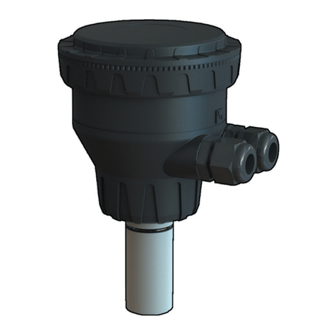
FIP FLS F6.61 User manual

1
FLS F6.61
HOT TAP FLOW MAGMETER
SAFETY INSTRUCTIONS
General Statements
• Do not install and service the product without following the Instruction
Manual.
• This item is designed to be connected to other instruments which can be
hazardous if used improperly. Read and follow all associated instrument
manuals before using with it.
• Product installation and wiring connections should only be performed by
qualied staff.
• Do not modify product construction.
Installation and Commissioning Statements
• Remove power to the instrument before wiring input and output connections.
• Do not exceed maximum specications using the instrument.
• To clean the unit, use only chemical compatible products.

2
PACKING LIST
Please verify that the product is complete and without any damage. The
following items must be included:
• F6.61 hot tap ow sensor
• Instruction Manual for F6.61 Hot tap ow sensor
• USB pen drive with interface software
• USB cable for instrument/PC interface
DESCRIPTION
The new FLS F6.61 Hot Tap Insertion Magmeter is a owmeter without moving
mechanical parts which can be applied for the measurement of dirty liquids so
long as they are conductive and homogeneous. The sensor can provide three
different options: frequency output to be connected to FLS ow monitors, 4-20
mA output for long distance transmission and PLC connection and the new
volume pulse output freely settable. FLS F6.61 Insertion Magmeter is provided
with an USB interface and a dedicated software (freely downloadable from
FLS web site) which allows to easily set by a PC all parameters according
to specic installation requirements. The sensor can be assembled in a wide
dynamic range of pressurized pipe sizes from DN 50 (2”) to DN 900 (36”)
using a standard clamp saddle and an isolation ball valve.

3
TECHNICAL DATA
General
• Pipe Size Range: DN50 to DN900 (2” to 36”). Special version on request for
other sizes. Please refer to Installation Fitting section for more details
• Max Flow Rate Range:
from 0.05 to 8 m/s (0.15 to 26.24 ft/s)
• Full Scale: 8 m/s (26.24 ft/s)
• Linearity: ± 1% of reading + 1,0 cm/s
• Repeatability: ± 0.5% of reading
• Enclosure: IP65
• Materials:
- case: PC/ABS
- gasket: EPDM
• Wetted Materials:
- sensor body: 304 SS/PVDF
- o-rings: EPDM or FPM
- electrodes: 316LSS
Electrical
• Power Supply:
- 12 to 24 VDC ± 10% regulated (reverse polarity and
short circuit protected)
- maximum current: consumption: 250 mA
- protective earth: < 10 Ω
• Current output:
- 4-20 mA, isolated
- max. loop impedance: 800 Ω @ 24 VDC - 250 Ω @ 12 VDC
- positive or negative ow indication
• Solid State Relay output:
- user selectable as MIN alarm, MAX alarm,
Volumetric, Pulse Out, Window alarm, Off
- optically isolated, 50 mA MAX sink, 24 VDC MAX
pull-up voltage
- max pulse/min: 300
- hysteresis: User selectable
• Open Collector output (Frequency):
- type: Open Collector NPN
- frequency: 0 – 800 Hz
- max. pull-up voltage: 24 VDC
- max. current: 50 mA, current limited
- compatible with FLS M9.02, M9.03, M9.50, M9.07, M9.08 and M9.10.
• Open Collector output (Direction):
- type: Open Collector NPN
- max. Pull-up Voltage: 24 VDC
- max. Current: 50mA, current limited
- ow direction:
0 VDC arrow-wise
+ VDC anti arrow-wise

4
Environmental
• Storage Temperature: -30°C to +80°C (-22°F to 176°F)
• Ambient Temperature: -20°C to +70°C (-4°F to 158°F)
• Relative Humidity:0 to 95% (non-condensing)
• Fluid conditions:
- homogeneous liquids, pastes or slurries, also with
solid content
- Min Electrical Conductivity: 20 μS
- Temperature:
PVDF bottom version: -10 °C to +60 °C (14 °F to 140°F)
• Max. operating pressure:
- 16 bar @ 25°C (232 psi @ 77°F)
- 8.6 bar @ 60°C (124 psi @ 140°F)
Standards & Approvals
• Manufactured under ISO 9001
• Manufactured under ISO 14001
• CE
• RoHS Compliant
• GOST R

5
DIMENSIONS
INSTALLATION
Pipe Location
• The six most common installation congurations shown in g. 1 help in
selecting the best location in the pipeline for paddlewheel ow sensor as well
for magmeter ow sensor.
• The three congurations in g. 2 ensure that the pipe is always full: for a
correct measurement the sensor can NOT be exposed to air bubbles at any
time.
• The three installations in Fig. 3 should be avoided unless you are absolutely
sure the sensor is not exposed to air bubbles.
• In gravity-ow systems the connection to the tank must be designed so the
level does not drop below the outlet: this to avoid pipe to draw air in from the
tank causing a inaccurate measurement of sensor (see Fig. 4).
• For more information, please refer to EN ISO 5167-1.
• Always maximize distance between ow sensors and pumps.
Magmeter electronic device
Sliding rod
AISI 304 SS joint for sensor installation
Pressure intake
Process connection 1 ¼” gas threaded
AISI 304 SS adjustable sensor body
AISI 316 L electrodes and PVDF bottom
1
2
3
4
5
6
7

6
Fig.1
Fig.2
Fig.3
Fig.4

7
Set the sensor to work
The assembly and set to work of the instrument are carried out by two simple
steps that allow a quick and precise installation:
1. INSTALLATION OF THE SENSOR ON THE WET-TAP CLAMP SADDLE
2. VERTICAL POSITIONING OF THE SENSOR INTO THE PIPE
Warning: the F6.61 allows installation into pressurised pipes without system
shutdown; we recommend to pay maximum attention when screwing the
clamping bolts of the measuring rod. The rod is pushed upwards by the
internal pressure, for this reason not work up the rob.
Note: lubricate the steel rod to reduce frictions with the O-rings. This will help
the installation, measurement and positioning operations.
1. INSTALLATION OF THE SENSOR ON THE WET-TAP CLAMP SADDLE
Warning: these installations steps can be applied to every wet-tap clamp
saddle with the following properties:
-Branch minimum diameter : 33 mm
-Branch thread : 1 1/4” GAS (cylindrical)
• Assemble the saddle or weld-on the adapter in the desired position to install
the sensor.
Drill the pipe. Use a 35 mm ( in.) milling cutter.
Remove the drilling machine. Be careful to block the uid using the proper
intercepting plate or ball valve (see Fig. 1).
• Wrap several turns of Teon tape around the steel joint threads to prevent
leaks. Screw the Stainless Steel joint, together with the measuring rod and the
sensor, in the saddle branch.
• Be careful to x the sensor body in the upper position (see Fig.2).
• Tight the safety chain and x it.
• Remove the intercepting plate or open the ball valve to the full open position
(perpendicular to pipe).
Fig.1 Fig.2

8
Fig.4Fig.3
Fig.5
2. VERTICAL POSITIONING OF THE SENSOR INTO THE PIPE
• Be sure the sensor is in the upper position.
• Calculate the DISTANCE between the sliding bush C (Fig. 2) and the sensor
body:
DISTANCE “L” [mm] = (0.15 x Internal Diameter) +S (wall thickness) +K
(distance between external pipe and end of the thread) - 15
• Move and x the sliding bush at the calculated DISTANCE from the Stainless
Steel joint
• Turn the special screws E out (Fig. 2) and push the rod downwards to get the
sliding bush being in contact with the Stainless Steel joint
• Move and x the sliding bush at the calculated DISTANCE from the Stainless
Steel joint (see Fig.4)
• Turn the special screws E out (see Fig. 2) and push the rod downwards to
get the sliding bush being in contact with the Stainless Steel joint.
Make sure the reference screw F (see Fig. 5) on the top pf the rod is
PARALLEL to the axis of the pipe and x again the sensor tightening the
special screws.
Tight the safety chain and x it using the special ring G (see Fig. 5).
Bind the sensor rod by the safety chain: it is pushed upward by the internal
pressure.

9
REAR TERMINAL VIEW
WIRING
General recommendation
Always ensure the power supply is switched off before working on the device.
Make wiring connections according to wiring diagrams.
• Terminals accept 26 to 12 AWG (0.08 to 2.5 mm2)
• Strip around 10 mm (0.4”) of insulation from the wire tips and tin bare ends to
avoid fraying.
• Ferrules are suggested when connecting more than one wire to a single
terminal.
• Remove the upper part of the terminals for an easy cabling.
• Insert wire tip or ferrule completely into the terminal and x with the screw
until nger tight.
• Do not route the sensor, DC power, or 4-20mA cables in conduit containing
AC power wiring. Electrical noise may interfere with sensor signal.
• Routing the sensor cable in grounded metal conduit can help prevent
electrical noise and mechanical damage.
Specic info
Pull the electrical cables through liquid tight connectors.
Use electrical cables with the proper external diameter for the liquid tight
connector.
PG11/PG9: external diameter between 2-7 mm (0.079-0.276”)

10
POWER/LOOP WIRING DIAGRAM
Stand-alone application,
no current loop used
Connection to a PLC/Instrument with ONE separate power supply
or
Connection to a PLC with built-in
power supply (3 wire connection)
Power Supply
12 - 24 VDC
12 - 24 VDC
+ VDC
- VDC
A
+ LOOP
- LOOP
1
2
3
4
Power Supply
Power Supply
Internal PLC
connection
4 - 20mA Loop Input
4 - 20mA Loop Input
PLC Terminals
+ VDC
- VDC
A
+ LOOP
- LOOP
1
2
3
4
Power Supply
12 - 24 VDC
12 - 24 VDC
PLC / Instrument
4 - 20mA Loop Input
4 - 20mA Loop Input
Power Supply
12 - 24 VDC
12 - 24 VDC
PLC / Instrument
4 - 20mA Loop Input
4 - 20mA Loop Input
+ VDC
- VDC
A
A
+ LOOP
- LOOP
1
2
3
4
+ VDC
- VDC
+ LOOP
- LOOP
1
2
3
4
Power Supply
12 - 24 VDC
12 - 24 VDC
PLC / Instrument
4 - 20mA Loop Input
4 - 20mA Loop Input
Power Supply
12 - 24 VDC
12 - 24 VDC
PLC / Instrument
4 - 20mA Loop Input
4 - 20mA Loop Input
+ VDC
- VDC
A
A
+ LOOP
- LOOP
1
2
3
4
+ VDC
- VDC
+ LOOP
- LOOP
1
2
3
4
Connection to a PLC / Instrument with TWO separate power supplies
or
Power Supply
12 - 24 VDC
12 - 24 VDC
Power Supply
12 - 24 VDC
12 - 24 VDC
PLC / Instrument
4 - 20mA Loop Input
4 - 20mA Loop Input
Power Supply
12 - 24 VDC
12 - 24 VDC
Power Supply
12 - 24 VDC
12 - 24 VDC
PLC / Instrument
4 - 20mA Loop Input
4 - 20mA Loop Input
+ VDC
- VDC
A
A
+ LOOP
- LOOP
1
2
3
4
+ VDC
- VDC
+ LOOP
- LOOP
1
2
3
4
Power Supply
12 - 24 VDC
12 - 24 VDC
Power Supply
12 - 24 VDC
12 - 24 VDC
PLC / Instrument
4 - 20mA Loop Input
4 - 20mA Loop Input
Power Supply
12 - 24 VDC
12 - 24 VDC
Power Supply
12 - 24 VDC
12 - 24 VDC
PLC / Instrument
4 - 20mA Loop Input
4 - 20mA Loop Input
+ VDC
- VDC
A
A
+ LOOP
- LOOP
1
2
3
4
+ VDC
- VDC
+ LOOP
- LOOP
1
2
3
4

11
Imax = 50 mA
Internal PLC
connection
COM
N.O.
5
6
PLC
Imax = 50 mA
Power sup.
Power sup.
O.C. IN
O.C. IN
C
SOLID-STATE RELAY WIRING DIAGRAM
Connection to a PLC with NPN input Connection to a PLC with PNP input
COM
N.O.
5
6
PLC
Imax = 50 mA
Power sup.
Power sup.
O.C. IN
O.C. IN
C
Internal PLC
connection
Connection to a PLC / Instrument
digital input with separate Power
Supply
Connection to a PLC / Instrument
digital input for Voltage Free Contacts
(REED)
PLC
DIGITAL INPUT N
DIGITAL INPUT 2
DIGITAL INPUT 1
REF PLC
COM
Imax
N.O.
6
5
10 Kohm
COM
N.O.
C
6
5
Power Supply
12 - 24 VDC
12 - 24 VDC
PLC / Instrument
Digital INPUT
Digital INPUT
The alarm is off during normal
operation and goes ON according to
Relay setting.
If Imax > 50 mA use external Relay.
COM
N.O.
N.C.
COM
5
6
N.O.
External Relay
V= 12-24 VAC/VDC
Imax = 50 mA
Imax
Imax
+V
-V
Connection to an User
Connection to an User
COM C
6
5 N.O.
AC or DC
Power
User
COM
C
6
5 N.O.
AC or DC
Power User
COM
C
6
5 N.O.
AC or DC
Power
User
COM C
6
5 N.O.
AC or DC
Power User
Imax = 50 mA Imax = 50 mA
Imax = 50 mA
Imax = 50 mA Imax = 50 mA
Imax = 50 mA

12
- DIR
NO
+ DIR
COM
8
7
6
5
+ FREQ
- FREQ10
9
+ V
DIR
FREQ IN
GND
7
6
5
6B
FLS monitor
terminals
- DIR
NO
+ DIR
COM
8
7
6
5
+ FREQ
- FREQ10
9
- DIR
NO
+ DIR
COM
8
7
6
5
+ FREQ
- FREQ10
9
PLC
Power sup.
Power sup.
O.C. IN
O.C. IN
Internal PLC
Connection
Power Supply
24 VDC
24 VDC
PLC / Instrument
Digital INPUT
Digital INPUT
- DIR
NO
+ DIR
COM
8
7
6
5
+ FREQ
- FREQ10
9
+ V
DIR
FREQ IN
GND
7
6
5
6B
FLS monitor
terminals
- DIR
NO
+ DIR
COM
8
7
6
5
+ FREQ
- FREQ10
9
PLC
Power sup.
Power sup.
O.C. IN
O.C. IN
- DIR
NO
+ DIR
COM
8
7
6
5
+ FREQ
- FREQ10
9
Power Supply
24 VDC
24 VDC
PLC / Instrument
Digital INPUT
Digital INPUT
Internal PLC
Connection
NO
- DIR
NO
+ DIR
COM
8
7
6
5
+ FREQ
- FREQ10
9
+ V
DIR
FREQ IN
GND
7
6
5
6B
FLS monitor
terminals
- DIR
NO
+ DIR
COM
8
7
6
5
+ FREQ
- FREQ10
9
- DIR
NO
+ DIR
COM
8
7
6
5
+ FREQ
- FREQ10
9
PLC
Power sup.
Power sup.
O.C. IN
O.C. IN
Internal PLC
Connection
Power Supply
24 VDC
24 VDC
PLC / Instrument
Digital INPUT
Digital INPUT
- DIR
NO
+ DIR
COM
8
7
6
5
+ FREQ
- FREQ10
9
+ V
DIR
FREQ IN
GND
7
6
5
6B
FLS monitor
terminals
- DIR
NO
+ DIR
COM
8
7
6
5
+ FREQ
- FREQ10
9
PLC
Power sup.
Power sup.
O.C. IN
O.C. IN
- DIR
NO
+ DIR
COM
8
7
6
5
+ FREQ
- FREQ10
9
Power Supply
24 VDC
24 VDC
PLC / Instrument
Digital INPUT
Digital INPUT
Internal PLC
Connection
NO
OPEN COLLECTOR WIRING DIAGRAM
Connection to FLS Instruments
Connection to a PLC NPN Open Collector input
Connection to a PLC/Instrument digital input with separate Power Supply
Please refer to K-Factor tables
for PLC setting (p.16)
Imax = 50 mA
- DIR
NO
+ DIR
COM
8
7
6
5
+ FREQ
- FREQ10
9
+ V
DIR
FREQ IN
GND
7
6
5
6B
FLS monitor
terminals
- DIR
NO
+ DIR
COM
8
7
6
5
+ FREQ
- FREQ10
9
- DIR
NO
+ DIR
COM
8
7
6
5
+ FREQ
- FREQ10
9
PLC
Power sup.
Power sup.
O.C. IN
O.C. IN
Internal PLC
Connection
Power Supply
24 VDC
24 VDC
PLC / Instrument
Digital INPUT
Digital INPUT
- DIR
NO
+ DIR
COM
8
7
6
5
+ FREQ
- FREQ10
9
+ V
DIR
FREQ IN
GND
7
6
5
6B
FLS monitor
terminals
- DIR
NO
+ DIR
COM
8
7
6
5
+ FREQ
- FREQ10
9
PLC
Power sup.
Power sup.
O.C. IN
O.C. IN
- DIR
NO
+ DIR
COM
8
7
6
5
+ FREQ
- FREQ10
9
Power Supply
24 VDC
24 VDC
PLC / Instrument
Digital INPUT
Digital INPUT
Internal PLC
Connection
NO
Imax = 50 mA
Frequency Output Direction Output
Frequency Output Direction Output
Frequency Output Direction Output
Imax = 50 mA
Imax = 50 mA
Please refer to K-Factor tables
for PLC setting (p.17)

13
EARTHING
The magmeter normally is uninuenced by low levels of electrical noise. In
some applications it is necessary to connect the sensor to earth to eliminate
electrical noise.
The earthing can be done as following described:
• connecting the Ground Wire (black wire from the sensor body) to an External
Earthing passing through a cable gland.
• in case of plastic pipes, connecting the Ground Wire (black wire from the
sensor body) to metallic inserts ( such as anged earthing rings ) into the
plastic pipe before and after the magmeter and then connecting them together
to an External Earthing. Fluid earths must be in direct contact with the uid
near to the magmeter.
Note: If present, the shield from the output cable must be terminated only at
the remote instrument. Do not connect this shield at both ends.

14
CALIBRATION
Manual Calibration
Manual calibration can be done setting the micro switches on PCB in the
proper combination in according with the pipe size (from d20-DN15 up to
d>200-DN>180) where sensor will be installed. Positions are reported in the
following table.
Lock position is a No Functioning Combination while the USB combination is
for accessing to the USB connection.
The setting has to be done before powering up the instrument.
F6.61 provides a frequency output (0Hz@0m/s - 800Hz@8m/s) by a
Open Collector (connectors 9-10) and an analog output (4mA@0m/s –
20mA@8m/s).
Both outputs are proportional to the ow velocity and so to the ow rate.
Moreover a Open Collector (connectors 7-8) is dedicated to specify the ow
direction.
In manual calibration the S.S.R. cannot be set and consequently used.
Switch 1 Switch 2 Switch 3 Switch 4 Diameter
Off Off Off Off Lock
Off On On Off D63
Off On On On D75
On Off Off Off D90
On Off Off On D110
On Off On Off D125
On On On On D140
On On Off Off 160
On On Off On D200
On On On Off > D200
On On On On USB

15
CALIBRATION BY USB
The F6.61 hot tap magmeter can be connected to a PC and the operator can
be connected to a PC and the operator can calibrate the instrument and set
all parameters using dedicated software on USB pen drive (software can be
dowloaded freely from FLS website)
Procedure for setting
- plug FLS Pen Drive into a USB port of PC
- open FLS Pen Drive folder
- install Java software: a internet connection is required. Installer software is
able to search for updated Java version automatically. In case of troubles,
please contact Technical Assistance at info@snet.it
- install FLS Calibration software
- launch FLS Calibration software
- set all MicroSwitches in ON position
- power the F6.61
- plug USB on the F6.61 PCB
- plug USB into a USB port of PC
- FLS Calibration software recognizes the F6.61 PCB
Software structure
The FLS Calibration software features following sub-views:
• Settings
• Calibration
• Output mA
• Digital Output
• Simulation
• View Data
• Download Data
Excluding View Data Section and Download Data Section, in each previous
sub-view you can set different parameters and the following actions are
allowed:
- Update: for data updating
- Reset: for going back to default data
- Help: for functions explanation and for undertaking the Remote Assistance
procedure (internet connection is required)
View Data sub-view summarizes status of measurement, analog output, digital
output including Volume Totalizer .
Download Data sub-view summarizes instrument parameters and following
actions are allowed:
- Download Data: to update instrument with new settings
- Download Default: to reload Default settings
- Save: to generate a le containing all set parameters
- Load: to load directly a le containing a instrument conguration

16
MIN MODE MAX MODE
Flow
Time
Hysteresis
Output relaxed
Output energized
Setpoint
Flow
Time
Hysteresis
Output relaxed
Output energized
Setpoint
OUTPUT MODE
The F6.61 hot tap ow magmeter features 1 solid state relays and 1 analog
output 4-20mA in addition to a Open Collector for frequency remoting (mainly
for the interfacing of F6.61 with a FLS monitor) and a Open Collector for the
ow direction remoting.
SSR output (connectors 5-6) can be set in the following way:
WINDOW OUT MODE PULSE MODE
Flow
Time
Setpoint
Hysteresis
Hysteresis
Output relaxed
Output energized
Setpoint
Pulse duration
Volume Volume Volume
Pulse duration Pulse duration
Output relaxed
Output energized
Flow
Time
Setpoint
Hysteresis
Hysteresis
Output relaxed
Output energized
Setpoint
WINDOW IN MODE

17
F6.61 K-FACTOR TABLE (ONLY FOR FREQUENCY
OUTPUT)
K-Factor is the number of pulses which a sensor produces for one liter of
measured uid. Here below all K-Factors for water at room temperature are
listed.
K-Factor values can depend on the installation conditions. K-Factor has to
divide the frequency generated by F6.61 in order to achieve the ow rate (l/s).
Please contact your dealer for K-Factor values not included in the table.
Metal Strap-on saddles
Part No. DN/
Size
O.D.
min
O.D.
max K-Factor
SZIC080IHT 80 88 104 20,22
SZIC100IHT 100 112 126 12,99
SZIC125IHT 125 140 154 5,31
SZIC150IHT 150 168 234 3,67
SZIC200IHT 200 218 286 2,03
SZIC250IHT 250 272 344 1,31
SZIC300IHT 300 322 384 0,9
SZIC350IHT 350 425 458 0,67
SZIC400IHT 400 406 472 0,53
SZIC450IHT 450 475 516 0,4
Metal Strap-on saddles
Part No. DN/
Size d/R K-Factor
SZIC080IHT 80 19,02
SZIC100IHT 100 11,28
SZIC125IHT 125 4,83
SZIC150IHT 150 3,31
SZIC200IHT 200 1,95
SZIC250IHT 250 1,24
SZIC300IHT 300 0,88
SZIC350IHT 350 0,73
SZIC400IHT 400 0,54
SZIC450IHT 450 -
Metal Strap-on saddles
Part No. DN/
Size d/R K-Factor
WAIXHT 350 0,67
WAIXHT 400 0,53
WAIXHT 450 0,4
WAIXHT 500 0,34
WAIXHT 600 0,23
WAIXHT 700 -
WAIXHT 800 -
WAIXHT 900 -
Installation on cast iron pipes Installation on other metal pipes
Installation on cast iron pipes

18
ORDERING DATA
Part No. Version Power
supply Length Main wetted
materials Enclosure Flow Rate
Range
Weight
(gr.)
F6.61.01 Hot-tap 12-24
VDC 615mm 304 SS/
PVDF/316L SS IP65 0.05 to 8 m/s
(0.15 to 25 ft/s) 6000
Part No. Name Description Weight
(gr.)
F6.KC1
Magmeter
Compact
mounting kit
Plastic adapter with compact cap and locking nut 137
M9.SP4.1 PG 11 PG 11 complete cable gland (2 o-rings and cap) 12
F1.SP3 Isolation Valve 2" Brass Ball Valve 1800
F1.SP5 Isolation Valve 1 1/4" Brass Ball Valve 1800
F1.SP6 2" to 1 1/4"
Reduction Zinc Plated Steel 2" BS male to 1 1/4" BS female 405
F1.SP7 2" to 1 1/4"
Reduction Zinc Plated Steel 2" NPT male to 1 1/4" BS female reduction 405
F6.60M.
SP1.S Electronic device Magmeter electronic device with 4-20mA output and freq.
Output /volumetric pulse output 180
F3.61M.
SP01
Magmeter ow
sensor for Hot
Tap installation
304 SS/PVDF body 1000
SPARE PARTS
Correction formula for K-Factor calculation according to real internal
diameter:
K-Factor_NEW = (K-Factor x ID²) / ID_NEW²
ID = Value in the table for the internal diameter (in mm)
ID_NEW = New value for the real internal diameter (always in mm)
K-Factor = Value in the table
K-Factor_NEW = New K-Factor value for the specied internal diameter
Example:
Nominal Pipe Size (DN) = 100 mm
New Internal Diameter = 104 mm
Forumla: K-Factor_NEW = (51.02 x 100²) / 104² = 20,52

19
NOTE

20
FIP - Formatura Iniezione Polimeri S.p.A.
Loc. Pian di Parata
16015 Casella
Genova - Italy
Tel. +39 010 96211
Fax +39 010 9621209
www.flsnet.it
IMF661E - 09/2015
Table of contents
Other FIP Measuring Instrument manuals
Popular Measuring Instrument manuals by other brands

Capelec
Capelec CAP2600 user manual

Meilhaus Electronic
Meilhaus Electronic RedHand Scope user manual
Klein Tools
Klein Tools MM6000 instruction manual
YOKOGAWA
YOKOGAWA ROTAMASS Total Insight user manual

socomec
socomec DIRIS A-30 operating instructions
Rice Lake
Rice Lake PROFIBUS DP Installation and programming manual
