Fire Chief SITEWARDEN SP400RF User manual

3 Lands End Way
Oakham
Rutland U.K.
LE15 6RB
Phone: 0330 999 0019
Email: sales@rechiefglobal.com
www.rechiefglobal.com
QUICK START GUIDE
The instructions overleaf should be carefully read before attempting
any installation of this system. Also, it is essential that you decide on
the requirements of the system, the devices needed and the locations
of the devices before you start to pair and install the system.
Every Sitewarden RF system requires a MASTER unit, which will be
the rst SP400RF unit that you set up. This can then be used as a
stand-alone site alarm functioning on its own, or it can be paired with
up to 9 additional SLAVE units.
SP400RF
Radio Linked Fire Alarm
Phone: 0330 999 0019
Email: sales@rechiefglobal.com
www.rechiefglobal.com
Phone: 0330 999 0019
Email: sales@rechiefglobal.com
www.rechiefglobal.com
Radio Linked Fire Alarm
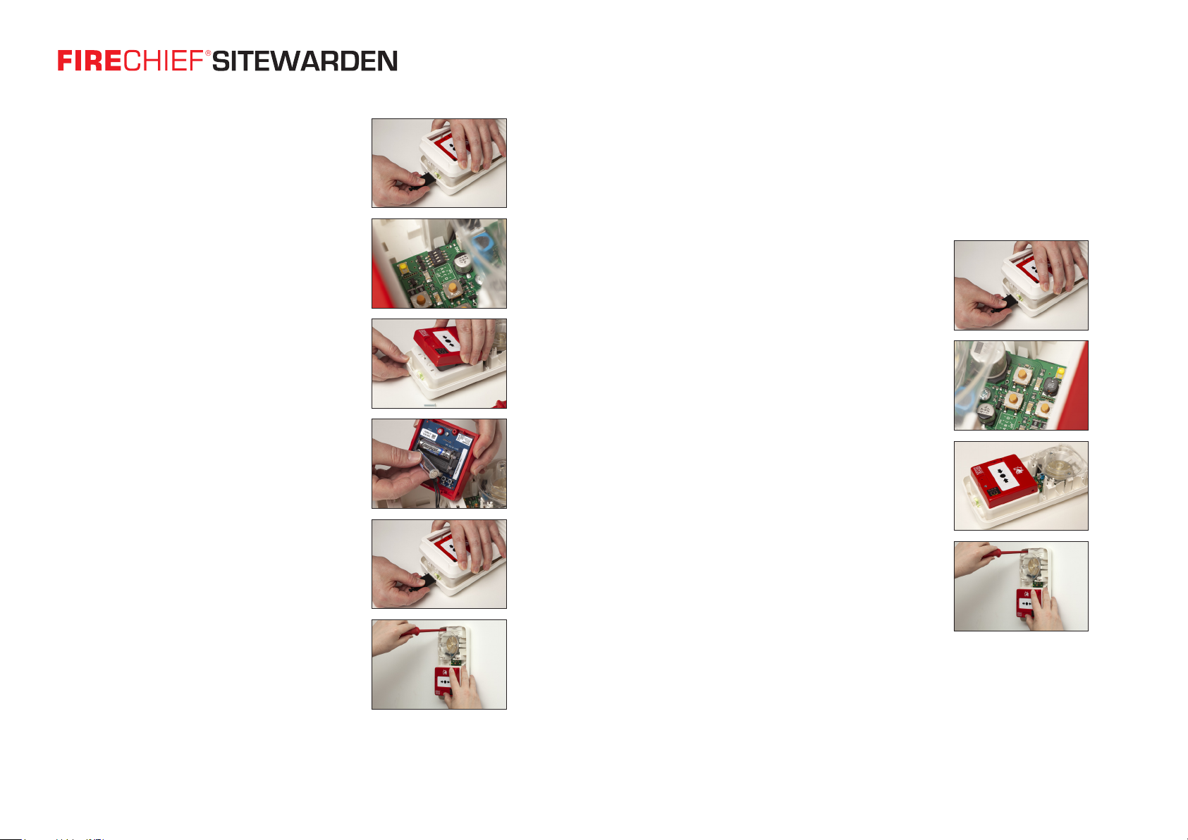
1. Open the case of the site alarm using the
black multifunction key supplied.
2. Locate the four switches mounted on
the circuitboard. If this is the rst
device in your system, ensure that you
make it the MASTER unit by moving
Switch 1 (A) to the o position.
3. Remove the screw from the front of the
manual call point and carefully lift the call
point from the alarm base.
4. Insert the batteries supplied observing
the polarity indicated – you will
hear a short series of beeps, followed by
three dual tones which indicates that the
system is now ready to operate. Replace
the call point cover and screw.
5. If you are intending to pair additional
units to this MASTER, please do not
mount the unit in its nal position or
replace the cover, as you will need access
to the unit whilst pairing the additional
units and the MASTER will need to be in
close proximity to the other units
you wish to pair.
6. If you are using your Sitewarden SP400RF
as a stand-alone alarm, mount the unit in
the desired location and replace the
cover. Your device is now ready to be used.
If you wish to use your SP400RF as part of a Sitewarden RF
system, then each additional unit will need to be paired to the
MASTER unit. The Sitewarden RF system comprises of additional
SP400RF units, separate SC400RF call points, additional SS400RF
sounder beacon units and also SD400RF smoke detectors. A
system can contain up to a maximum of 10 units including the
MASTER unit. Please see the instructions for pairing SLAVE units
set out below. Each pairing process is described individually for
each type of additional unit you wish to add to the system.
7. Prepare each SLAVE unit to be paired by
installing batteries following steps
1 – 4 as above.
8. With the cover o the SLAVE device,
locate the PROG switch on the circuit
board, just above the call point.
9. With the SLAVE site alarm near to the
MASTER site alarm, press and release
the PROG button on the SLAVE unit.
10. A number will appear on the LED
display on the front of each unit and
you will hear a conrmation tone from
each. The number is the address of
that SLAVE unit.
SP400RF
The units are now paired. Further SP400RF units can be added to
the system, up to a total of 10 including the MASTER unit.
Popular Fire Alarm manuals by other brands

Simplex
Simplex 4010ES Quick reference guide

Global Fire Equipment
Global Fire Equipment VALKYRIE AS manual

Zeta Alarm Systems
Zeta Alarm Systems INFINITY ID2 installation manual

System Sensor
System Sensor 22051TLE-RF-26 Installation and maintenance instructions

Pittway
Pittway Notifier AM2020 troubleshooting guide

Ampac
Ampac ZoneSense user manual


Radionics
Radionics Radionics 9124 user guide

UniPOS
UniPOS FD 7120 instruction manual

Teletek electronics
Teletek electronics SensoMAG MRB50 installation instructions

bolid
bolid S2000-IP-03 instruction manual

FIREGUARD GLOBAL
FIREGUARD GLOBAL FG-S01_AP quick start guide

Panasonic
Panasonic MEW01091 operating instructions