Fire Pro FP-20SE Instruction sheet

Installation, Wiring
and Earthing
Guidelines
for Cylindrical Aerosol units
Version 2, 24-06-2016

General Installation Guide Line about the FirePro Aerosol Generators
FP-20SE/T/TH, FP-40S/T, FP-80S/T,FP-100S, FP-200S,FP-500S.
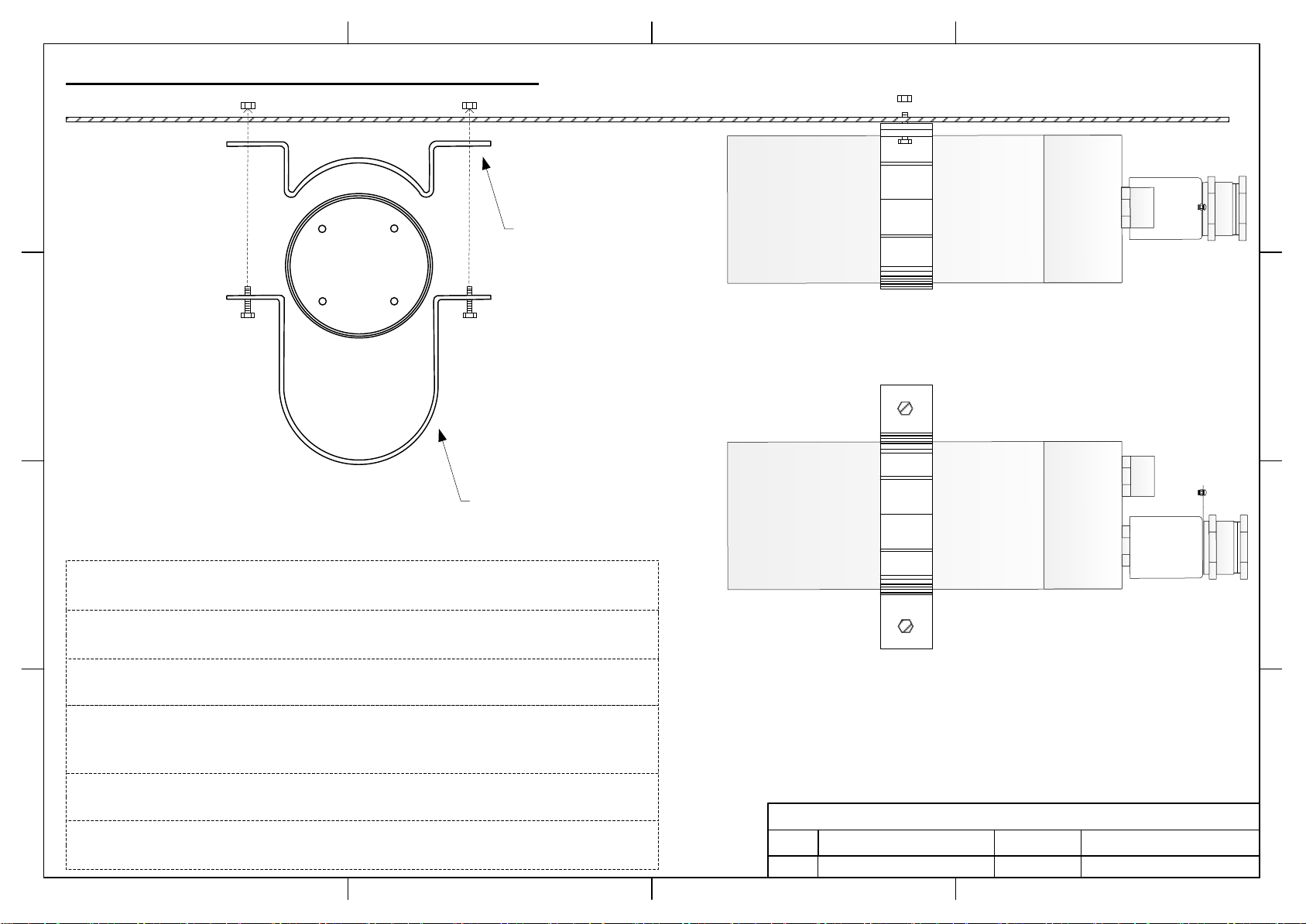
FP-20SE/T/TH:
Step 1: Take the “Bracket” and place it on the aerosol generator.
Step 2: Align “Bracket” holes with surface material holes.
Step 3: Select type of screws suitable to the surface material to be fixed (these screws are not
supplied with the kit).
Step 4: Pass the screws through the aligned holes and fix them on the surface material.
Step 5: The aerosol generator is ready for cable connections.
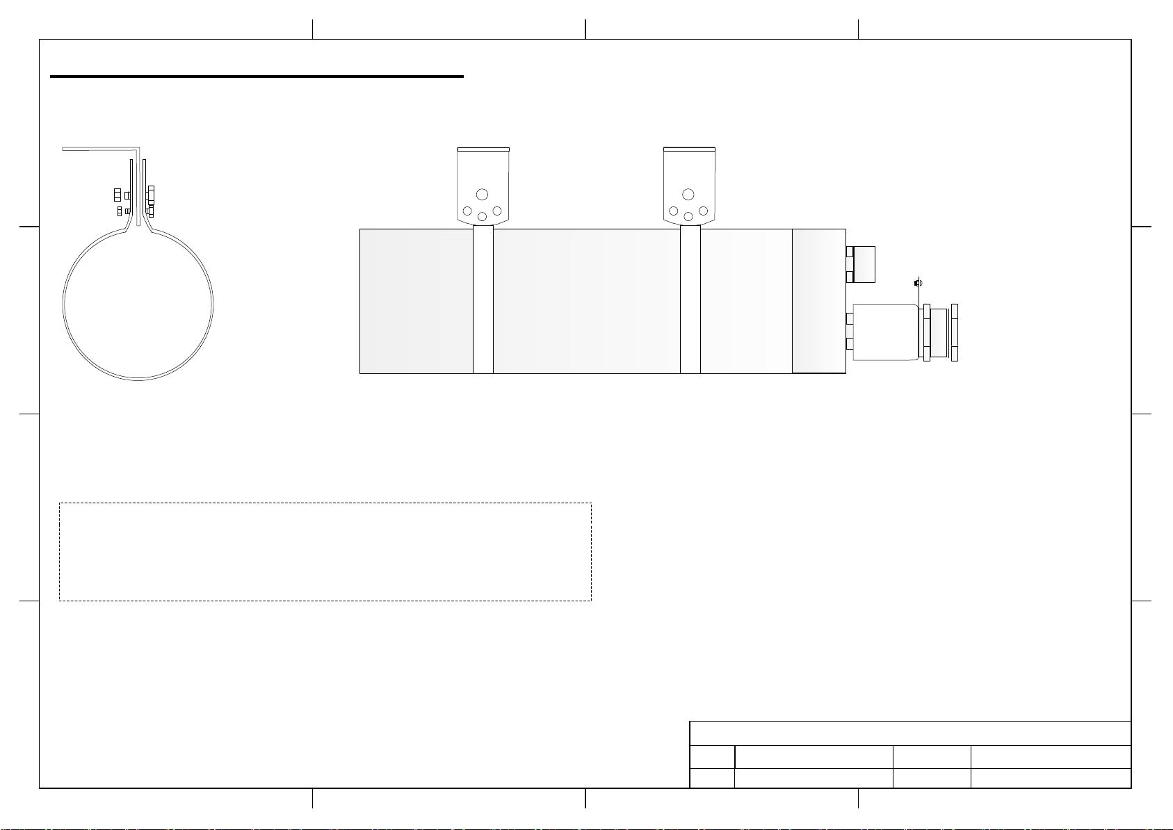
FP-40S/T, FP-80S/T:
Step 1: Take the “Bracket part 1” and place it on top of the aerosol generator.
Step 2: Take the “Bracket part 2” and place it under the aerosol generator.
Step 3: Align “Bracket part 1” holes with “Bracket part 2” holes.
Step 4: Select type of screws suitable to the surface material to be fixed (these screws are not
supplied with the kit).
Step 5: Pass the screws through the aligned holes and fix them on the surface material.
Step 6: The aerosol generator is ready for cable connections.
FP-100S/200S:
Step 1: Pass through the Aerosol Generator the Ring Bracket.
Step 2: Take ( L ) bracket and place it inside the ( Ring ) bracket.
Step 3: Align ( L ) bracket holes to the ( Ring ) bracket holes.
Step 4: Pass the screws through the aligned holes and tide them with the spanner key 11,13 to the
nuts. Use screw size “M8” for the longer hole and screw size “M6” for the smaller hole.
Step 5: Select type of screws suitable to the surface material to be fixed (these screws are not
supplied with the kit).
Step 6: Pass the selected screws through the ( L ) bracket holes and fix them on the surface material.
Step 7: The aerosol generator is ready for cable connections.
FP-500S:
Step 1: Pass through the Aerosol Generator the 2 Ring Brackets.
Step 2: Take each ( L ) bracket and place it inside the ( Ring ) bracket.
Step 3: Align each ( L ) bracket holes to the ( Ring ) bracket holes.
Step 4: Pass the screws through the aligned holes and tide them with the spanner key 11,13 to the
nuts. Use screw size “M8” for the longer hole and screw size “M6” for the smaller hole.
Step 5: Select type of screws suitable to the surface material to be fixed (these screws are not
supplied with the kit).
Step 6: Pass the selected screws through the ( L ) bracket holes and fix them on the surface material.
Step 7: The aerosol generator is ready for cable connections.

FirePro
FirePro Systems
REV. BYDATEDESCRIPTION
Aerosol Generator FP-20SE/T/TH
1.0 Generator Installation guide line 24/06/2016 Michaelides Loucas
D
C
B
A
4321
D
C
B
A
4321
32mm Diameter
U-Type Metal
Bracket
FirePro
Front View
Side View
Bottom View
Step 5
The aerosol generator is ready for cable connections.
Step 4
Pass the screws through the aligned holes and fix them on the surface material.
Step 3
Select type of screws suitable to the surface material to be fixed (these screws are
not supplied with the kit).
Step 2
Align “Bracket” holes with surface material holes.
Step 1
Take the “Bracket” and place it on the aerosol generator.
Page 2

FirePro
FirePro
FirePro Systems
REV. BYDATEDESCRIPTION
Aerosol Generator FP-40S/T
1.0 Generator Installation guide line 24/06/2016 Michaelides Loucas
D
C
B
A
4321
D
C
B
A
4321
Front View
Side View
Bottom View
Page 3
50mm Diameter
U-Type Metal
Bracket
Step 5
The aerosol generator is ready for cable connections.
Step 4
Pass the screws through the aligned holes and fix them on the surface material.
Step 3
Select type of screws suitable to the surface material to be fixed (these screws are
not supplied with the kit).
Step 2
Align “Bracket” holes with surface material holes.
Step 1
Take the “Bracket” and place it on the aerosol generator.
FirePro
FirePro Systems
REV. BYDATEDESCRIPTION
Aerosol Generator FP-80S/T
1.0 Generator Installation guide line 24/06/2016 Michaelides Loucas
D
C
B
A
4321
D
C
B
A
4321
C4080BRS1
Bracket Part 1
C4080BRS2
Bracket Part 2
FirePro
Front View
Side View
Bottom View
Step 1
Take the “Bracket part 1” and place it on top of the aerosol generator.
Step 6
The aerosol generator is ready for cable connections.
Step 5
Pass the screws through the aligned holes and fix them on the surface material.
Step 4
Select type of screws suitable to the surface material to be fixed (these screws are
not supplied with the kit).
Step 3
Align “Bracket part 1” holes with “Bracket part 2” holes.
Step 2
Take the “Bracket part 2” and place it under the aerosol generator.
Page 4

FirePro Systems
REV. BYDATEDESCRIPTION
D
C
B
A
4321
D
C
B
A
4321
Aerosol Generator FP-100S & FP-200S
1.0 Generator Installation guide line 24/06/2016 Michaelides Loucas
FirePro
Step 7
The aerosol generator is ready for cable connections.
Step 6
Pass the selected screws through the ( L ) bracket holes and fix them on the surface
material.
Page 5
Step 5
Select type of screws suitable to the surface material to be fixed (these screws are
not supplied with the kit).
Step 4
Pass the screws through the aligned holes and tide them with the spanner key 11,13
to the nuts. Use screw size “M8” for the longer hole and screw size “M6” for the
smaller hole.
Step 2
Take ( L ) bracket and place it inside the ( Ring ) bracket.
Step 3
Align ( L ) bracket holes to the ( Ring ) bracket holes.
Step 1
Pass through the Aerosol Generator the Ring Bracket

FirePro Systems
REV. BYDATEDESCRIPTION
D
C
B
A
4321
D
C
B
A
4321
Aerosol Generator FP-500S
1.0 Generator Installation guide line 24/06/2016 Michaelides Loucas
Step 1
Pass through the Aerosol Generator the 2 Ring Brackets
FirePro
Page 6

FirePro Systems
REV. BYDATEDESCRIPTION
D
C
B
A
4321
D
C
B
A
4321
Aerosol Generator FP-500S
1.0 Generator Installation guide line 24/06/2016 Michaelides Loucas
Step 2
Take each ( L ) bracket and place it inside the ( Ring ) bracket.
FirePro
Step 3
Align each ( L ) bracket holes to the ( Ring ) bracket holes.
Page 7
FirePro Systems
REV. BYDATEDESCRIPTION
D
C
B
A
4321
D
C
B
A
4321
Aerosol Generator FP-500S
1.0 Generator Installation guide line 24/06/2016 Michaelides Loucas
FirePro
Step 4
Pass the screws through the aligned holes and tide them with the spanner key 11,13
to the nuts. Use screw size “M8” for the longer hole and screw size “M6” for the
smaller hole.
Page 8

FirePro Systems
REV. BYDATEDESCRIPTION
D
C
B
A
4321
D
C
B
A
4321
Aerosol Generator FP-500S
1.0 Generator Installation guide line 24/06/2016 Michaelides Loucas
FirePro
Step 5
Select type of screws suitable to the surface material to be fixed (these screws are
not supplied with the kit).
Page 9
This manual suits for next models
9
Other Fire Pro Portable Generator manuals


