Fire Pro 08879 User manual
Digital Voltage Sensitive Relay
Model 08879
Rev 1.0
Contents
1Introduction........................................................................................................................... 1
1.1 General Information ............................................................................................... 1
2Components List ................................................................................................................. 2
3Operations............................................................................................................................. 2
3.1 Mounting ................................................................................................................... 2
3.2 Power Supply Monitoring ..................................................................................... 2
3.3 Automatic Cutoff..................................................................................................... 2
3.4 Fire Indicator Panel (FIP) .................................................................................... 2
3.5 Cabling Requirements........................................................................................... 3
4Installation ............................................................................................................................ 3
5Operation............................................................................................................................... 4
6Commissioning..................................................................................................................... 4
7Servicing and Maintenance.............................................................................................. 4
8Troubleshooting .................................................................................................................. 4
9Specifications ....................................................................................................................... 4
1Introduction
1.1 General Information
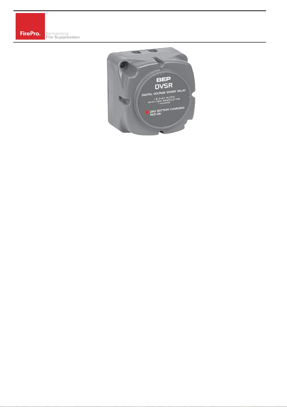
The FP-08879 Digital Voltage Sensitive Relay (DVSR) provides a plug-in solution for DC power
supply monitoring and battery isolation. When installed the FP-08879 monitors and
automatically isolates the incoming power supply when the incoming power drops below an
ideal operating voltage. This avoids deep discharge of batteries.
Digital Voltage Sensitive Relay
Model 08879
Rev 1.0
2Component List
FP-08874 Power Control Module
Digital Voltage Sensitive Relay, 12 - 24vDC,
automatic low voltage cutoff
3Operations
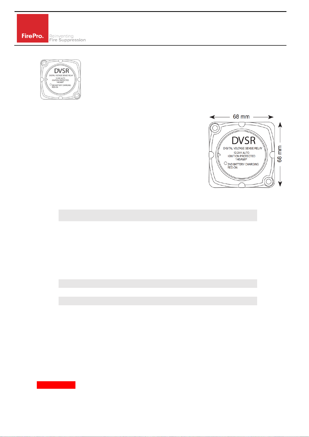
3.1 Mounting
The Module must be mounted using the bracket supplied.
No penetrations are to be made through the casing.
The Power Control Module enclosure is rated IP65, mounting
should be away from where it may be affected by water.
3.2 Power Supply Monitoring
The FP-08879 DVSR is a multi-voltage to operate on either
12vDC or 24vDC. When the DVSR is first powered, it will automatically sample the incoming
power supply:
12vDC (7-15.9 volts)
or
24vDC (16 –32 volts)
The DVSR requires continuous power for 5 seconds to determine the incoming power. Once
power mode is selected, the DVSR will remain in this mode until power is disconnected.
3.3 Automatic Cutoff
Once the FP-08879 DVSR has determined the operating voltage, it will monitor the incoming
power supply. The incoming power supply must drop below operating voltage continuously
for 4 seconds before the DVSR will automatically cut off the incoming power supply.
Mode
Engages
Cutoff
12vDC
13.4vDC
12.8vDC
24vDC
26.8vDC
25.6vDC
3.4 Fire Indicator Panel (FIP)
The FIP will then switch to backup power until the primary power supply is restored.
Backup Power Control Modules are designed to provide power to the fire system for a period
of 24 hours. Actual backup power will be available based on the condition of the batteries and
this will largely be determined by machine run time.
The backup battery is charged by the primary power supply, and approx 1 hour of run time
will provide 1 hour of battery backup, if the backup batteries have been allowed to run flat.
IMPORTANT –where Sealed Lead Acid Backup Batteries (Models 8870 and 08871) have been
installed these will need to be replaced. SLA batteries will not recharge once they have run
flat. These can be swapped for FP-08872 NiMh battery pack.
When primary power is restored, the fire system will be operational, and will stay fully

Digital Voltage Sensitive Relay
Model 08879
Rev 1.0
operational until the backup battery is depleted.
Note that FirePro systems have a failsafe, the FirePro Generator will self-activate once the
temperature reaches 300ºC.
3.5 Cabling Requirements
The cables are marked RED on the module, and
the plugs are setup Male/Female to ensure
correct installation.
Cables are colour coded for easy identification.
When installing system, cables should be only
connected to the correctly coded cable.
4Installation
1. Ensure fire control panel is not in an alarm/fault condition.
2. The machine MUST NOT be running.
3. Unplug the Power supply to the FIP.
4. Unplug the FP-14016 Battery Lead from Battery Pack and plug into FP-08879 DVSR. The
DVSR requires a minimum of 5 seconds to allow sampling of the incoming power supply,
to determine operating voltage. This will be indicted by flashing of the LED indicator. When
sampling is complete the LED indicator will stop flashing and remain illuminated.
5. Connect the FP-08879 to a compatible Power Control Module (FP-08872/08873). The
“Charging” LED indicator will illuminate on the Power Control Module connected correctly.
6. It is now safe to connect the power supply to the FIP.
Colour
Circuit
Red 1
Power Supply
Red 2
Backup Batteries
Yellow 1
Activation
Yellow 2
Activation Delayed
Green 1
Detection 1
Green 2
Detection 2
Blue
Discharge Advice
Orange
Siren/Strobe
White
Relay Output
Digital Voltage Sensitive Relay
Model 08879
Rev 1.0
5Operation
The FP-08879 DVSR operates when the unit is installed and the Main power is active. Should
the main supply fail or drop below operating volatage, the module automatically cuts off the
primary power supply. When the primary supply has been connected the LED will illuminate
to indicate that the primary power supply is available.
When the primary supply has failed or dropped below operating volatage will flash once every
5 seconds to indicate that the primary power supply is being cut off.
If the primary power supply voltage is too high, the DVSR will flash rapidly.
6Commissioning
Commissioning should be performed after installation.
1. Ensure fire control panel is not in an alarm/fault condition.
2. Run the machine, this should allow full power to the FIP.
3. TURN OFF machine and the Lower voltage will automatically disconnect primary power
supply (depending on state of main machine battery voltage) and ensure LED indicator
begins flashing.
4. Ensure power supply to FIP automatically switches to the backup batteries. This will be
indicated by the LED on the installed Power Control Module switching off, and the FIP
should remain operational.
5. Ensure fire control panel remains operational and out of fault condition.
7Servicing and Maintenance
Inspection and servicing of the installed fire system should occur in accordance with the
relevant Australian Standards. Monitoring and operation of any installed modules should be
tested as outlined in 6. Commissioning.
8Troubleshooting
Problem
Possible Cause
Solution
LED not illuminating
Poor/Reversed connection to
vehicle battery
OR
Incoming power Voltage not high
enough to engage DVSR
Check connection and of battery
lead and any extension cables.
Test voltage of primary power
supply.
Charge or replace primary batteries.
LED flashing rapidly
Incoming power voltage is above
upper limit of operating voltage.
Check main supply voltage.
9Specifications
12vDC Main Supply
24vDC Main Supply
Dimensions - mm
68L x 68W x 50D
Operating voltage
9-15vDC
16-32vDC
Disengages
12.8vDC
25.6vDC
Engages
13.4vDC
26.8vDC
Fault-sensing
Indicators for Power Source(s) Only
Operating Temp.
-40 to 85ºC
Popular Relay manuals by other brands

Omron
Omron SR203M installation instructions

ASO Safety Solutions
ASO Safety Solutions ELMON classic 32-312 Brief Instruction

Acuity Controls
Acuity Controls GR2400 Operation, Programming and Maintenance Manual

Yamatake-Honeywell
Yamatake-Honeywell 7800 Series manual

Honeywell
Honeywell Silent Knight SK-Relay Installation and maintenance instructions

Doepke
Doepke Dupline DSM 4E operating instructions


