Acuity Controls GR2400 User manual

LC&D Operation,
Programming and
Maintenance Manual
Project Name:
Project Location:
Acuity Agency:
Order #:
PO #:
Project ID:
Date:
Controls TechSupport:
1-800-535-2465 - option 1: nLight; option 2: SSI; option 3: Fresco; option 4: Synergy; option 5: LC&D/Bluebox; option 6 ROAM
To preschedule a call with tech support (providing a 4 hour business lead time) go to the following
link: http://www.acuitybrands.com/resources/schedule-support-request
Additional TechnicalLiterature:
https://www.acuitybrands.com/products/controls/lcd
1

Table of Contents
GR2400 Installation and Operation Manual ............................................................................3
GR2400 Basic Programming Guide .......................................................................................71
Chelsea Digital Switch Programming Guide ..........................................................................83
Additional Resources (Product specific user guides, Programming documents, etc) ………103
2

2
4
6
8
10
12
14
16
18
20
22
24
26
28
30
32
LINE
LOAD
LINE
LOAD
LINE
LOAD
LINE
LOAD
LINE
LOAD
LINE
LOAD
LINE
LOAD
LINE
LOAD
LINE
LOAD
LINE
LOAD
LINE
LOAD
LINE
LOAD
LINE
LOAD
LINE
LOAD
LINE
LOAD
LINE
LOAD
SnapLink
Relay
NO
20A
120VAC/1 HP
277VAC/2 HP
SnapLink
Relay
NO
20A
120VAC/1 HP
277VAC/2 HP
SnapLink
Relay
NO
20A
120VAC/1 HP
277VAC/2 HP
SnapLink
Relay
NO
20A
120VAC/1 HP
277VAC/2 HP
SnapLink
Relay
NO
20A
120VAC/1 HP
277VAC/2 HP
SnapLink
Relay
NO
20A
120VAC/1 HP
277VAC/2 HP
SnapLink
Relay
NO
20A
120VAC/1 HP
277VAC/2 HP
SnapLink
Relay
NO
20A
120VAC/1 HP
277VAC/2 HP
SnapLink
Relay
NO
20A
120VAC/1 HP
277VAC/2 HP
SnapLink
Relay
NO
20A
120VAC/1 HP
277VAC/2 HP
SnapLink
Relay
NO
20A
120VAC/1 HP
277VAC/2 HP
SnapLink
Relay
NO
20A
120VAC/1 HP
277VAC/2 HP
SnapLink
Relay
NO
20A
120VAC/1 HP
277VAC/2 HP
SnapLink
Relay
NO
20A
120VAC/1 HP
277VAC/2 HP
SnapLink
Relay
NO
20A
120VAC/1 HP
277VAC/2 HP
SnapLink
Relay
NO
20A
120VAC/1 HP
277VAC/2 HP
NEWCO
High Voltage High Voltage
Low Voltage
120 vac
277 vac
120vCir cuit Breaker
277vTermal Fuse
Neutral
SCROLL
UP
SCROLL
DOWN
EXIT
DELETE HELP
TAB
UP
TAB
DOWN
ENTER
1
3
5
7
9
11
13
15
17
19
21
23
25
27
29
31
LINE
LOAD
LINE
LOAD
LINE
LOAD
LINE
LOAD
LINE
LOAD
LINE
LOAD
LINE
LOAD
LINE
LOAD
LINE
LOAD
LINE
LOAD
LINE
LOAD
LINE
LOAD
LINE
LOAD
LINE
LOAD
LINE
LOAD
LINE
LOAD
120 OFF
277
SnapLink
Relay
NO
20A
120VAC/1 HP
277VAC/2 HP
SnapLink
Relay
NO
20A
120VAC/1 HP
277VAC/2 HP
SnapLink
Relay
NO
20A
120VAC/1 HP
277VAC/2 HP
SnapLink
Relay
NO
20A
120VAC/1 HP
277VAC/2 HP
SnapLink
Relay
NO
20A
120VAC/1 HP
277VAC/2 HP
SnapLink
Relay
NO
20A
120VAC/1 HP
277VAC/2 HP
SnapLink
Relay
NO
20A
120VAC/1 HP
277VAC/2 HP
SnapLink
Relay
NO
20A
120VAC/1 HP
277VAC/2 HP
SnapLink
Relay
NO
20A
120VAC/1 HP
277VAC/2 HP
SnapLink
Relay
NO
20A
120VAC/1 HP
277VAC/2 HP
SnapLink
Relay
NO
20A
120VAC/1 HP
277VAC/2 HP
SnapLink
Relay
NO
20A
120VAC/1 HP
277VAC/2 H P
SnapLink
Relay
NO
20A
120VAC/1 HP
277VAC/2 HP
SnapLink
Relay
NO
20A
120VAC/1 HP
277VAC/2 HP
SnapLink
Relay
NO
20A
120VAC/1 HP
277VAC/2 HP
SnapLink
Relay
NO
20A
120VAC/1HP
277VAC/2 HP
LosAngeles, CA (800) 345-4448
GR2400 Series
Control Card
AUTO HAND
On Line
Assign
1
3
5
7
9
11
13
15
2
4
6
81
0
1
14
16
17
19
21
23
25
27
29
31
18
20
22
24
26
28
30
32
OnLine
Indicator
OnLine
Indicator
LosAngeles, CA
(800)345-4448
FactoryEntered
Address
PCC1
To
Photocell
Interfaceto Photocell
SnapLink
Relay
NO
20A
120VAC/1 HP
277VAC/2 HP
SnapLink
Relay
NO
20A
120VAC/1 HP
277VAC/2 HP
SnapLink
Relay
NO
20A
120VAC/1 HP
277VAC/2 HP
4
Off
3
Off
2
Off
1
Off
4
On
3
On
2
On
1
On
SnapLink
Relay
NO
20A
120VAC/1 HP
277VAC/2 HP
GR 2400
Manual
Installation & Operation
Lighting Control & Design, Inc. •Los, Angeles, CA •
support: 800-345-4448
•
fax: 323-226-1000
Pictorial
Quick Hook-Up
Pages 1- 6
Go to Appendix III
For Final Check Out
Page 66
www.lightingcontrols.com
GR2400 Complete Manual.pdf 1 8/6/2007 1:45:27 PM
3

GR2400 Complete Manual.pdf 3 8/6/2007 1:45:28 PM
4

The GR 2400 Manual Index
Quick Start Instructions
Hooking up the GR 2400 System Page 2
One Line Diagram Page 3
Telephone Connection Page 3
Typical Panel Schedule Page 4
Wire Labeling & Phone Hook Up Page 5
Connect & Terminate Bus Page 6
GR 2400 System in a bit more detail
Typical Hook Up 2 Panels 2 Switches Page 8
Long Distances between Switches Page 8
Single panel Lots of Switches Page 8
Too Many Switches on section of Bus Page 9
Things to Know about the bus Page 10
Too Long a Bus Page 11
Parts of the System
Relay (Types of) Page 12
Changing Relays Page 13
Dual Voltage Input Card Page 14
DigiLink Page 14
GR 2404 Page 16
GR 1416,2432 & 2448 cards Page 18
Board Addressing Page 18
Modes Page 18
8 & 16 Zone and Discrete Mode Page 19
GR 2416 Card Page 20
Checking the Mode Page 21
Assigning Relays to a Zone Page 21
Viewing which relays are in a zone Page 22
Sequence Speed Page 22
Flashing LEDs What they mean Page 23
Other Accessory Boards Page 24
Programming the GR 2400 System
Picture of Programmer Page 25
Navigating the Clock Page 26
The USER Menu Page 27
Review/Changing a Schedule Page 27
Mon to Fri Schedule Page 28
By Day Schedule Page 28
After Midnight Page 29
Schedules and Groups Page 30
Disabling a Schedule Page 30
Programming a Group Page 30
Group Properties Page 31
When to Set the Blink Warning Page 32
Manual Override Menu Page 32
Setup Menu Page 32
Contacting LC&D Page 33
Restricted Menu Page 33
System Setup Menu Page 33
Set Time & Date Page 33
Edit Holidays Page 33
System Option Page 35
Keyboard Lock Code Page 35
Select Location Page 35
Display Options Page 36
Naming Menu Page 36
What and When Menu Page 37
Scheduled Events Page 37
What Controls Groups Page 38
What Controls Relays Page 38
Relay Properties Menu Page 38
Changing the Time Delay between
relays Page 38
Specifying Normally Closed Relays Page 39
Sentry Switch Option Page 40
Other individual Relay Parameters Page 40
5

The GR 2400 Manual Index
(Cont)
Addressing Bus Scan Page 40
Auto Addressing Page 41
Read Address Page 41
Bus Diagnosis Page 41
Group Loads Menu Page 42
ON/OFFSequencing Page 42
Programming a Sequence Page 43
Programming Switches Page 43
Programming Buttons Page 43
Coying a Switch Page 44
Additional Features in Clock version 4.16 Page 45
Photocell Control Cards
Single Input Card Page 50
Three Input Card Page 51
Programming Photocells Page 51
Daylight Harvesting Page 52
Special Situations Page 52
Appendix I: The Restricted Menu
Appendix II: Start up Check List.
Pages 58through 62
Specifications Page 63
The Restricted Menu Page 53
Factory Set Up Menu Page 53
Addresing Bus Scan Page 53
Error Statistics Page 53
Panel Switch Types Page 54
Relay Properties Page 54
Remote System Menu Page 54
Remote Password Page 54
Dial Up Host Page 55
Owner Settings Menu Page 55
Erase Options Menu Page 55
Erase Clock Memory Page 56
Changing the Mode on a GR 2416 Card Page 57
6

G
G
GR
R
R2
2
24
4
40
0
00
0
0M
M
MA
A
AN
N
NU
U
UA
A
AL
L
L
How to install the Lighting Control & Design GR 2400 System
7

Quick Start Instructions
Hooking up the GR 2400 System
The GR 2400 system is very simple to put together.
The basic system consists of:
1)The Master Panel like the one on the left, it will have a
Clock Display and usually a modem.
2) A Switch or Switches like the Chelsea switch shown
above.
3) Sometimes there will be a Photocell.
4) Sometimes there will be additional slave relay panels.
They do not have the clock display or the modem in them.
5) Sometimes there will also be other accessories. These
are discussed later in the manual.
All these items are hooked together on a digital bus of
Category 5, four twisted pair data cable.
GR 2432 Relay Panel with 32 Relays Rated at 20 amps 277 Vac
Left barrier removed to show complete relay.
Outdoor Photocell
Chelsea 6 Digital Switch
C
Clock Display
MODEM
Page 2
8

Typical Hook Up
Breaker
Panel
LOAD
Neutral
Digital Switches
Locator Light Plus Pilot LEDs
on all buttons including "Off"
buttons.
Electronics
Relay
Slave
Relay
Panel(s)
4TwistedPair
Cat 5 Cable with
RJ45 Connectors at each end
Make sure there are
"terminators" at each
end of the bus.
Relay PCO
Outdoor Photocell
GR2400 PCI
Indoor Photocell
PCC-1
Single Input
Photocell Card
or
PCC-3, 3 Input
Photocell Card
could also be
mounted in the
nearest relay
panel.
2ea#18AWG
2ea#18AWG
MASTER
Relay
Panel
323
226-6615
Phone
Connection:
Contractor to
ensure it is
installed.
Write Phone #
on plate
One Line Diagram
This one line diagram shows what
types of low voltage wires are
used to connect the parts of the
system together.
The Cat 5 cable must be looped
through each item on the bus with
NO SPURS!
The items on the bus (switches,
panels, photocell cards, etc.) may
be arranged on the bus in any
order, its not important. The only
point to be careful of in large sys-
tems is getting enough voltage to
the switches. There are several
pages of the manual that cover
this point later.
Telephone Connection
LC & D systems come pre pro-
grammed from the factory with
the data on hand when we ship it.
However at start up there are
usually some minor changes and
some trouble shooting to be done.
If the telephone hook up is avail-
able a factory tech can check out
the system rapidly over the phone.
Not having the phone line in can
slow project completion.
PLAN AHEAD! Get the phone line installed in
timeforstartup!Call LC&Dbeforeinstallation
forquicktips.CallLC&Dagainbeforestartup
for help with final programming. (800) 345-4448.
Page 3
9

Page 4 Typical Connection
Most jobs are pre programmed at the
factory. You must land the wires from the
breakers to the designated relays and
connect them to the correct loads for the
programming to work!
Note: If you use a gutter the neutrals do
not need to be sent through or landed in
the panel.
The panel schedules should be at the
beginning of this manual and also in a
pocket on the door of each panel.
Please follow the panel schedule and
you will save everyone a lot of work.
GUTTER
Circuit Breakers
Relay Panel
Typical Panel Schedule
10

Page 5
Label the line feed wire with the number of the breaker.
Use a separate breaker for powering the electronics.
This prevents a problem circuit from disabling the whole
system.
Note that the 120 Vac feed is protected by a circuit
breaker mounted to be accessible when the door is on
the panel while the 277VAC feed is protected by self
resetting thermal fuses. The rotary switch also has a
position for OFF if the system needs to be de-powered.
Did we mention it is a good idea to get the phone line
installed early! It may not get used much so it could be
placed in parallel with a fax machine and plugged in as
necessary.
1
120 Vac
Circuit
Breaker
277Vac
Thermal
Fuses
INPUT Selector
Switch
Label Wires
Connect Phone Line
Write Phone #
on Phone Plate
11

Page 6
Connect and Terminate the Bus
The “Bus Connectors” are all wired in parallel. Use Cat 5, 4 twisted pair wire.
1= (Nominal Ground or Common of System) The Green Pair wired together
2= (Data Wire “A”) The Orange wire of the Orange White Pair
3= (Data Wire “B”) The White wire of the Orange White Pair
4= (+12 Volt dc to power switches) The Blue White Pair wired together.
Note: In earlier manuals a different color code was used. If adding to an older
system make sure your color code is exactly the same as the old system.
On panel control cards there are two connectors. These are in parallel. It is a
good idea to have one cable come in and one out so that the bus can be “op-
ened” for trouble shooting.
Blue End of bus
Terminator Installed
Location of Terminator pins
on the back of a switch
Make sure the numbered
switches are connected at
the correct locations as per
the switch schedules or the
programming will be incor-
rect.
Back View of a Digital Switch
Showing the Bus Connector
Hook up.
Close Up of a Relay Panel control card
showing the four Bus Connectors. Two
RJ 45s and two “1-2-3-4 connectors.”
Cat 5 Cable
Note the HAND/AUTO switch. Use
this to keep the relays ON while
testing the system. All LEDs on the
control cards and switches will
still indicate even with the relays
locked ON.
12

Page 7
Connecting up the GR 2400 System.
Lighting Control & Design recommends the use of pre-
made and pre-tested Ethernet style cables. These can
even be pulled through conduit with little difficulty. In
most cases the cabling does not have to be in conduit
though plenum rated cable may be required.
The Wiring diagram shown is from www.lanshack.com.
They are also a good supply house for off the shelf pre-
made and tested cables at a cost that is way less than
one can make them oneself.
Cable Testers
A vital tool to have is a cable tester.
This ensures that cables are verified
in the field as being hooked up cor-
rectly. (90% of field problems are
caused by incorrectly installed
cables.) If each cable is tested just
before plugging it in these problems
go away. The cable tester and
crimper kit is available from LC &D
at cost. Call 800 345 4448 and ask
for Tech support.
Cable tester and crimper
kit available from LC & D
Inspect your crimps! A damaged or Old crimper will not seat each of
the contacts evenly. Though the cable may pass the tester any tug-
ging or mechanical stress can cause problems later.
Note: The cable tester will NOT work if any of the wires are
plugged into any card since 3 of the wires are shorted together to
carry 12 volts and 3 are shorted to carry ground.
Pair #
1-
White/Blue
2-
White/Green
3-
White/Orange
4-
White/Brown
Wire Pin
#
5
4
3
6
1
2
7
8
White/Blue
Blue/White
White/Green
Green/White
White/Orange
Orange/White
White/Brown
Brown/White
Wiring Scheme 568B
While the wiring scheme above is the most
commonly used wiring some jobs may have a
standard that more closely follows Telephone
company conventions Data hook up of 568A.
(which transposes the Green and Orange pairs)
This can also be used as long as both ends of
the cable are ALWAYS the same.
13

Single Panel with 10 switches will be OK with a wire length
of up to 200ft.
Panel A LCP 1
GND
+12V
DC
AB
4
3
2
1
GND
+12V
DC
4
3
2
1
AB
4
3
2
1
GND
+12V
DC
AB
GND
AB
+12V
DC
4
3
2
1
Blue White Pair
Orange/White
White/Orange
Panel A LCP 1
Switch 1 Switch 2
Panel B LCP 2
GR 2404 -DIM
Typical Hook up of a 2 Panel system with two Switches using
“1234" Connectors:
Panel A LCP 1
A panel at each end of the run increases the number of
switches and length of wire.
Panel B LCP 2
Switches with Long Distances Between Them and Multiple
Switches with only One Panel.
Cat 5 cable is 24 AWG and will carry 1 amp of current over 200 ft.
After that the resistance of the wire becomes too great and there will
not be enough voltage to run the electronics of the switches.
A system with a lot of switches or long distances between the panel
and the switches may require additional wire to handle the voltage
drop.
The calculations for this are a bit tricky and it is always better to be
safe than sorry. Here are some rules of thumb.
Each Switch takes about 100ma of current. Thus 10 switches equals about 1
amp. Cat 5 wire with RJ45s used three conductors for the power which aver-
ages out to about 1 ohm per 100ft.Per Ohms LAW V=IR , I=1amp R =2 Ohms
soVoltagedropwillbe2Volts)
There is also a limit to the amount of current a panel can provide to
drive switches.
Page 8
Green White Pair
Using the “1234" Connectors
Older systems have “1234" Connectors. These
are wired as shown on the left. New systems
use RJ 45 connectors only and the “1234" con-
nectors are being phased out. Note that the
1234 connectors use the Orange pair as the
Data pair while the RJ45s use the Blue pair as
the data pair. Should there be a situation that
needs a 1234 at one end and an RJ 45 at the
other make sure the connection is carefully
checked before it is connected.
Each 48 relay panel can drive 12 switches. For each
relaynotbeingdrivenanextraswitchcanbeadded
up to a maximum of 20.Thus a 32 relay panel can
have up to 20 switches. A panel at each end of the
line is better than having two panels at the beginning
of the line to drive all the switches.
14

Page 9
$LV
$LV
$LV $LV
$LV
$LV $LV
$LV
$LV
$LV
$LV
$LV $LV
$LV
$LV $LV
$LV
$LV
$LV
$LV
$LV
$LV
$LV
$LV
Example of a Tenant Improvement High Rise Core and Shell.
LCP 1 LCP 2
The booster wire can be 2 number 18s or just a short section
of Cat 5 with two pairs twisted together for +12 and two pairs
twisted together for Gnd.
Another solution is to get a “BUS BOOSTER” from LC & D
which is just a 12 volt power supply with RJ45 connectors on it
used to boost the voltage in the middle of the bus.
Also note: Never connect the bus “ground” to the actual “Earth”
ground. It is supposed to be a “floating” ground.
300 ft
$LV
$LV $LV$LV $LV
$LV
Add Gnd
&+12VONLY
Add Gnd
&+12VONLY
Getting out of trouble
Too Many Switches on a section of Bus
In this example the cat 5 Bus was wired before the equip-
ment and the manual were received. Though the electrician
knew what to do from a previous job he did not have this
number of switches on that job so had not run into this prob-
lem before.
By adding two sections of booster wire to boost the Ground
and +12 Volt connection he fixed his problem with voltage
drop to the switches.
15

Page 10
Terminator Terminator
The beginning and the end of the bus should be "terminated" even in systems with just a panel and a single switch. Terminators dampen reflections that could otherwise
cause data to get corrupted.
One might liken the bus to a rope with knots in it at every item on the bus. A termination could be considered to be the binding at the end of the rope to preventfraying.
SPUR
Items on the bus should be connected in sequence (no particular order needed) with no "SPURS." A Spur is any branch from the bus of more than a few (3) feet.
4000 ft
The bus may be up to 4000 ft long. Items must be connected in sequence. No Star Topologies allowed.
Note the way the bus has been drawn with an angle in and vertical out. This is the standard way to represent an RS 485 type data bus.
RS 485 is a Standard that describes the voltages associated with transmitting data on this type of bus.
NEVER run the bus close to current carrying conductors even if they are in conduit. 2ft away is good. NEVER EVER run the bus in the same conduit as
high voltage wires.(Even in cases where it is allowed by code.) In places with a very high Radio Frequency Field (ie near a Radio Station Antenna and
sometimes even high frequency ballasts can cause a problem)it may be necessary to use a shielded Cat 5 or run it in conduit.
Things to know about the BUS
16

Page 11
$LV
$LV
$LV
$LV
$LV
$LV
$LV
$LV
$LV
$LV
$LV
$LV
School Gym and Associated Rooms
Bus Length 3500 ft without
adding switch in Scorekeeper Sky Box
Score Keeper Sky Box
400Ft wire
Getting Out of Trouble
Too Long a Bus
In this example of a school Gym the switches and panels
were as shown in a concrete building with limited conduits.
There was no way to put everything on a straight line bus
and keep under 4000ft. The main problem was the Score
Keep’s switch which would have added close to 800 ft to the
bus. (Out and Back.)
The solution was to order an analog switch with a DigiLink
dry Contract input card instead of a digital switch for that
one location. The Analog switch requires two wires plus one
wire per button. (8 Wires for a 6 button switch.) For under
200 ft one can use Cat 5 and for longer use # 18 wire.
Change to Analog Switch and
home run wires to a “DigiLink”
17

Page 12
SnapLink Relays are rated at 277Vac 20Amps. Standard panels are
shipped with Normally Closed relays so that the relay will be on during
hook up and will default to ON when power is lost. This is especially nec-
essary for emergency circuits but is also very useful on normal circuits
during maintenance. Normally Open relays are also available.
SoftStart relays can be identified by a small box next to the terminal
block. Soft Start relays are only rated for use on 120Volt incandescent
lamp circuits. Please make sure that they are correctly connected and that
any changes made in the field uses them on incandescent loads. They will
not be damaged by switching Fluorescent loads or being run at 277 but
the extra money spent on the relay will give no benefit.
@Zero relays may be used on any type of load. They have a solid state
section that turns ON and OFF the relay at the zero cross point to reduce
contact burn. They should be used for loads that require frequent cycling.
They have a life of at least 250,000 throws and should last for close to a
million throws.
600 Volt 2 Pole Relay
Parts of the System:
Relays
Standard SnapLinkTM Relay
600 Volt 2 pole relays. These take up two
single pole relay spaces and are mechanically
linked 2 pole relays. They are used for dual
277Vac circuits that require a higher rating
(480Vac) than the standard 277 Vac relays.
These relays will be mounted in a special sec-
tion since they do not fit under the usual barri-
er.
2 Pole relays are driven by alternate outputs
from the control card. Thus if output 1 is driv-
ing a 2 pole, output 3 would be unused.
18

Page 13
L
O
A
D
L
I
N
E
I
N
L
O
A
D
L
I
N
E
Screwdriver
Blade
Changing Relays
Relays are mounted in "Snap Track." This is an insulating
holder that allows relays to be "Snapped" in and out.
First loosen the mounting screws for the barrier that both
acts a clamp and a cooling fin for the relays.
Remove the high voltage connections and unplug the low
voltage connections. Place a flat bladed screwdriver in the
notch at the front of the relay and twist and lift to pop the
relay out.
Put the replacement relay into the same location with the
back side of it engaged in the track. Place the flat bladed
screw driver blade on the front of the relay and give the end
of the screwdriver a sharp tap to snap the relay into the
track. Now reconnect the low and high voltage
connections.
I
N
Snaplink Latching Relay.
Introduced at the end of 2005 the Snaplink Latching
relay is a heavy duty 347 volt relay. It is designated
Normally Closed since it will snap to closed upon loss
of power.
The heavy construction ensures that any dead short
on the output is passed along to the circuit breaker
with minimal damage to the relay. The extra large ter-
minals can take 2 number 8 wires for loads at long
distances from the cabinet.
The Snaplink Latching relay is not a Zero Cross relay
yet is rated to switch 20 amps of High Output
Flourecent ballasts loads for 100,000 operations.
(Most smaller relays require a zero cross circuit to
handle High Output ballasts which have extremely
high inrush currents.)
19

Dual Voltage Input Card
Most systems are shipped with dual voltage input cards.
These have a rotary switch that selects OFF, 120 VAC or
277 VAC.
When 277Vac is connected there will be no voltage on the
120 Volt terminal and similarly when 120 Volts is selected
there will be no voltage on the 277Vac connector.
In the OFF position both the 120 and 277 volt inputs are dis-
connected.
The 277 Vac primary is protected with a thermal fuse, the
120 Vac primary is protected with a 1amp circuit breaker.
Page 14
B
BREAKER
DigiLink
The DigiLink Dry Contact Input Card is used to interface to
non LC & D equipment.
The DigiLink card is connected to the GR 2400 bus in the
usual way through the RJ 45 Connectors or the“1234” bus
connector.
It is most usually mounted inside one of the relay panels but
may also be mounted in a 6" by 4" by 4" box in any conve-
nient location.
When used with an Occupancy Sensor an additional power
supply may be needed to provide the auxiliary voltage
needed by that brand of sensor.
For the hook up diagrams below only some inputs are illus-
trated in order to conserve diagram space. The additional
inputs are wired the same way.
Note that a DigiLink appears in the clock programming win-
dows as a 14 button switch. Each input is programmed in
the exact same way as a switch button.
20
Table of contents
Other Acuity Controls Relay manuals
Popular Relay manuals by other brands
Rockwell Automation
Rockwell Automation Allen-Bradley 193-T1APM Installation instruction
Emirel
Emirel W 91 quick start guide

LS
LS META MEC Series instruction manual

ABB
ABB Relion 615 series installation manual
TSURUGA ELECTRIC
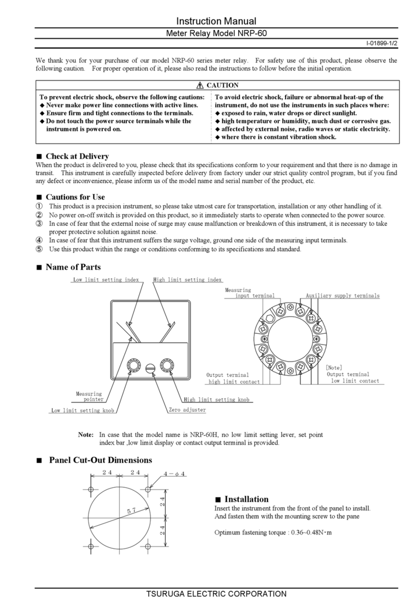
TSURUGA ELECTRIC NRP-60 instruction manual

Ampcontrol
Ampcontrol IPM V2 user manual
