Fire Pump 8100 Series User manual

C
e
S
e
e
ntri
f
e
rie
s
f
ug
a
s
81
0
a
l S
p
0
0,
8
p
lit C
8
15
0
ase
0
, 82
0
Fire
0
0,
9
Install
a
M
e
Pu
m
9
10
0
a
tion, Op
e
M
aintena
n
m
ps
0
e
ration, a
n
n
ce man
u
n
d
u
al

Series 8100/8150/8200/9100 Fire Pump
1 AC6102 Rev 03

AC61
0
0
2 Rev 03
EC De
c
Pump su
p
We, the ma
declare un
d
Horizontal
S
8150, 8200
fulfills the r
e
Directive(s)
Directives:
-
-
Standards
u
-
-
-
Pump su
p
We, the ma
n
declare und
e
Horizontal
S
8150, 8200,
fulfills the r
e
Directive, S
t
Directives:
-
Standards
u
-
-
The pump c
service until
has been d
e
Directive.
The technic
a
request by t
authorized
r
Community:
M
C
o
L
o
V
i
3
6
V
i
Brian Bu
s
Product
L
c
laration o
f
p
plied compl
e
nufacturer:
A-
C
82
0
Mo
r
US
A
d
er our sole res
p
S
plit Case Cent
r
,
and 9100; to
w
e
levant provisio
n
, Standard(s) o
r
Machinery D
i
Low Voltage
u
sed:
EN 809:199
8
EN ISO 121
0
EN 60204-1:
2
p
plied without
n
ufacturer:
A-
C
820
Mo
r
US
A
e
r our sole resp
o
S
plit Case Centri
f
and 9100; to w
h
levant provision
s
t
andard(s) or oth
Machinery D
i
u
sed:
EN 809:199
8
EN ISO 121
0
overed by this d
e
the equipment i
e
clared in confor
m
a
l file can be su
p
h
e competent n
a
epresentative e
s
auro Caldarde,
o
E Engineering
o
wara S.r.l. Uni
p
i
a Vittorio Lomb
6
075 Montecchi
o
i
cenza, Italy.
s
cher
L
ine Manage
r
f
Confor
m
e
te with drive
r
C
Fire Pump Sy
s
0
0 N. Austin Av
e
r
ton Grove, IL 6
0
A
,
p
onsibility that t
h
r
ifugal Fire Pum
w
hich this declar
n
s of the followi
n
r
other normativ
e
i
rective (2006/4
2
Directive (2006/
9
8
+A1:2009.
0
0:2010.
2
006+A1:2009.
drive
r
C
Fire Pump Sys
t
0 N. Austin Ave.
r
ton Grove, IL 6
0
A
,
o
nsibility that the
f
ugal Fire Pump,
h
ich this declara
t
s
of the followin
g
er normative do
c
i
rective (2006/4
2
8
+A1:2009.
0
0:2010.
e
claration must
n
n
to which it is to
m
ity with the pro
p
plied, in respon
s
a
tional authoritie
s
s
tablished in the
Manager,
p
ersonale,
ardi 14,
o
Maggiore,
Mort
o
m
ity
r
s
tems
e
.
0
053,
h
e product
p, Series 8100,
a
tion relates,
n
g European
e
document(s):
2
/EC).
9
5/EC).
t
ems
0
053,
product
Series 8100,
t
ion relates,
g
European
c
ument(s):
2
/EC).
n
ot be put into
be incorporated
visions of the
s
e to a reasone
d
s
, through our
European
o
n Grove, Illinoi
s
August 8, 201
4
d
s
4
2

Series 8100/8150/8200/9100 Fire Pump
3 AC6102 Rev 03

AC6102 Rev 03 4
Table of contents
1 Introduction …………………………………………………. 8
1.1 General …………………………………………… 8
1.2 Target Group ………………………………........... 8
1.3 Safety symbols used in this manual ……........... 8
1.4 Manufacturer ………………………………........... 8
1.5
A
dditional technical documents ………………… 8
2 Safety ………………………………………………………… 8
2.1 General …………………………………………… 8
2.2 Intended use …………………………………….. 8
2.3 Improper use ……………………………............ 8
2.4 Warning and Instruction Labels ……………….. 9
2.5 Personnel qualifications and training ………… 9
2.6 Safety awareness ………………………………… 9
2.7 Safety instruction for the user …………………. 9
2.8 Safety instructions for maintenance, inspection,
and installation ……………………………………. 9
2.9 Noise Emissions ………………………………….. 9
2.10 Unauthorized modification and manufacture of
spare parts ………………………………………… 9
2.11 Product Warranty …………………………………. 10
2.11.1 Coverage ………………………………………….. 10
2.11.2 Limitations ……………………………………….... 10
2.11.3 Warranty Claim …………………………………… 10
3 Applications ………………………………………………... 10
4 Operational Limits …………………………………………. 10
4.1 Pumped liquids ……………………………………. 10
4.2 Liquid temperature ……………………………….. 10
4.3 Pressure limits ……………………………………. 10
4.4
A
mbient temperature …………………………….. 10
4.5 Pump speed ………………………………………. 10
5 Delivery, handling, and storage ………………………… 11
5.1 Delivery ……………………………………….…. 11
5.2 Handling ………………………………………… 11
5.2.1 Bare shaft pump (Model 100) …….……………. 11
5.2.2 Complete pump unit (Model 150M) …………… 11
5.2.2.1 Bases supplied with lifting holes …….………… 11
5.2.2.2 Bases supplied without lifting holes …………… 11
5.2.3 Engine driven pump units (Model 150E) ……… 12
5.3 Storage ………………………….…………………. 12
5.3.1 Temporary storage ……………………………… 12
5.3.2 Long Term Storage ……….…………………… 12
6 Description ……………………………………………..…. 13
6.1 General …………………………………………… 13
6.2 Designation ………..……………………………. 13
6.3 Nameplate ………..……………………………… 13
6.3.1 Pump nameplate ………………………………… 13
6.3.2 Pump unit nameplate …………………………… 13
6.4 Design detail ……………………………………… 14
6.4.1 Casing …………..…………………………………. 14
6.4.2 Impeller …………………………………………….. 14
6.4.3 Shaft ……………………………………………… 14
6.4.4 Shaft sleeves ……………………………………… 14
6.4.5 Stuffing box ……………………………………… 14
6.4.6 Casing rings ……………………………………….. 14
6.4.7 Bearings ……………………………………..…….. 14
6.4.8 Bearing housings …….………………………..…. 14
6.4.9 Baseplate ………………………………………….. 14
6.4.10 Coupling ………………………………..………….. 14
6.4.11 Coupling Guard ………………….…….…………. 14
6.4.12 Rotation ……………………………………………. 14
6.5 Noise characteristics ……………………….……. 15
6.6 Scope of supply …………………….…………….. 15
6.7 Dimension and weights ………………………….. 15
7 Installation …………………….……..….…………………. 15
7.1 Location ……………………………………..…….. 15
7.2 Foundation ………………………………….…….. 15
7.3 Leveling the baseplate …………………….…….. 16
7.4 Grouting …………………………………..……….. 16
7.5 Initial Alignment ……………………………….….. 17
7.5.1 Straightedge method of alignment …………….. 17
7.5.1.1
A
ngular alignment ……………………….……….. 14
7.5.1.2 Parallel Alignment ………………………….…….. 17
7.5.2 Dial indicator method of alignment …………….. 17
7.5.2.1
A
ngular alignment ……………………….……….. 18
7.5.2.2 Parallel Alignment ………………………….…….. 18
7.5.3
A
lignment of grid couplings …….…………..….. 18
7.5.3.1 Mount seal and hubs …………………….………. 18

Series 8100/8150/8200/9100 Fire Pump
5 AC6102 Rev 03
7.5.3.2 Gap and Angular alignment (X-Y) ……………… 18
7.5.3.3 Parallel Offset Alignment (P) …………...………. 18
7.5.3.4 Insert Grid …………………………………………. 18
7.5.3.5 Pack with grease and assemble covers ………. 18
7.6 Pipe connections …………………………………. 19
7.6.1 Suction and discharge piping general
precautions ……………………………………… 19
7.6.2 Maximum forces and moments allowed on
pump flange ……………………………………… 20
7.6.2.1 8100 series Horizontal split case maximum
forces and moments allowed …………………… 20
7.6.2.2 8200 series Horizontal split case maximum
forces and moments allowed …………………… 20
7.6.2.3 9100 series Horizontal split case maximum
forces and moments allowed …………………… 20
7.6.3 Suction piping …………………………………… 22
7.6.4 Discharge piping …….……………………………. 23
7.6.5 Bypass piping …………………………………… 23
7.6.6 Cooling system ……………………..…………… 23
7.6.7 Exhaust system …………………………….…… 23
7.6.8 Pressure gages ………………………….……… 24
7.6.9 Stuffing box lubrication ………………………… 24
7.6.9.1 General guidelines ……………………………… 24
7.6.9.2 Packing …………………………………………… 24
7.7 Final Alignment …………………………………… 24
7.8 Electrical Connection …………………………… 24
8 Start-up, operation and shutdown ……………...……… 25
8.1 Start-up …………………………………………… 25
8.1.1 Preparation for start-up ………………………… 25
8.1.2 Priming …………………………………………… 25
8.2 Coupling Guard ………………..………………… 25
8.2.1 Removing the coupling guard ……………….… 26
8.2.2 Installing the coupling guard ……………………. 26
8.3 Operation ………………………………………… 27
8.3.1 General procedure ……………………………… 27
8.3.2 Optional Checklist ………………………………… 27
8.4 Shutdown ………………………………………… 27
8.5 Returning to service ……..……………………… 27
8.6 Freeze protection ……………..………………… 27
8.7 Field testing ……………………………………… 27
9 Maintenance …….......................................................... 28
9.1 General …………………………………………… 28
9.2 Maintenance interval ……………………………. 28
9.3 Lubrication ……………………………………….. 28
9.3.1 Lubricating grease requirements ……………… 28
9.3.2 Grease lubrication ………………………………. 29
9.3.3 Lubrication procedure ……………………………. 29
9.4 Packed stuffing box …………..………………… 29
9.4.1 Packing specifications …………………………… 29
9.4.2 Packing maintenance ……………………………. 29
9.4.3 Removal of packing ………………………………. 29
9.4.4 Installing packing …………………………………. 29
9.4.5 Packing adjustment ………………………………. 30
10Service ……………………………………………………… 31
10.1 Tools required …………………………………….. 31
10.2 Dismantling ………………………………………... 31
10.2.1 Rotating Element …………………………………. 31
10.2.2 Bearing housing ………………………………….. 31
10.2.3 Shaft seal - gland packing ………………………. 31
10.2.4 Shaft sleeve ……………………………………….. 31
10.2.5 Impeller and casing wear rings …………………. 32
10.3 Examination of parts ……………………………... 32
10.3.1 Casing and impeller ……………………………… 32
10.3.2 Shaft and sleeve ………………………………….. 32
10.3.3 Gaskets and O-rings ……………………………... 32
10.3.4 Bearings …………………………………………… 32
10.3.5 Bearing isolators and lip seals …………………. 32
10.4
A
ssembly ………………………………………….. 32
10.4.1 Wear Rings ……………………………………….. 32
10.4.2 Impeller …………………………………………….. 33
10.4.2.1 Series 8100, 8150 and 9100 …….……………… 33
10.4.2.2 Series 8200 ……………………………………….. 34
10.4.3 Bearings and bearing housings ………………… 34
10.4.3.1 Series 8100 ……………………………………….. 34
10.4.3.2 Series 8200 ……………………………………….. 35
10.4.3.3 Series 9100 ……………………………………….. 35
10.4.3.4 Series 8150 ……………………………………….. 35
10.4.4 Rotating Element …………………………………. 35
10.4.4.1 Series 8100 ……………………………………….. 35
10.4.4.2 Series 8200 ……………………………………….. 35
10.4.4.3 Series 9100 ……………………………………….. 35
10.4.4.4 Series 8150 ……………………………………….. 36
10.4.5 Casing Gaskets …………………………………… 36
10.4.6 Stuffing Box Assembly – Packing ……………… 36
10.5 Tightening torques ……………………………….. 36
10.5.1 Casing Bolts ………………………………………. 36
10.5.1.1 Tightening sequence …………………………….. 36
10.5.2 Other Bolt Locations …………………………… 37

AC6102 Rev 03 6
10.6 Spare Parts ………………………………………... 37
10.6.1 Ordering Spare Parts …………………………….. 37
10.6.2 Storage of spare parts …………………………… 37
11Troubleshooting …………………………………………… 39
12Replacement Parts ………………………………………… 41
12.1 Series 8100 Horizontal Split Case Fire Pump … 41
12.2 Series 8200 Horizontal Split Case Fire Pump … 43
12.3 Series 9100 Horizontal Split Case Fire Pump … 45
12.4 Series 8150 Horizontal Split Case Fire Pump … 47
A Appendix …………………………………………………..… 49
A
1 Coupling Guard Removal - non CE version …... 50
A
2 Changing pump rotation …………………………. 51

Series 8100/8150/8200/9100 Fire Pump
7 AC6102 Rev 03
AC6102 Rev 03 8
1 Introduction
1.1 General
The A-C Fire Pump product line of horizontal split case
centrifugal fire pumps are the product of careful
engineering and skilled workmanship and, if properly
installed, maintained, and operated, should deliver
efficient and trouble-free service.
This manual introduces the user to the pump unit and its
intended uses. It is extremely important that the
instructions for operating the pump safely are read,
understood and followed prior to handling the pump.
These instructions do not consider local regulations. The
user alone is responsible for ensuring that such
regulations are observed, including by those who are
installing the pump unit.
CAUTION
Read this manual carefully before installing,
operating, using and maintaining the pump.
Improper use of the pump can cause
personal injury and damage to property, and
may void the warranty.
NOTICE
Save this manual for future reference, and
keep it readily available at the location of the
unit.
1.2 Target Group
This manual is intended for use by personnel with
qualified training and experience in the operation and
maintenance of pumps used for fire suppression.
1.3 Safety symbols used in this
manual
WARNING
If these safety instructions are not followed, it
could result in serious personal injury or death,
or property damage.
CAUTION
If these safety instructions are not followed, it
could result in equipment malfunction of
damage.
WARNING
Electric Shock Hazard, failure to follow safety
instructions could result in personal injury or
death.
WARNING
The surface of the pump may be so hot that it
may cause burns or personal injury.
NOTICE
Instructions that are not safety related but
pertain to the operation of the pump.
WARNING
The sound pressure is so high that hearing
protection must be used.
NOTICE
Read the installation, operation and
maintenance instructions.
1.4 Manufacturer
A-C Fire Pump Systems
8200 N. Austin Avenue
Morton Grove, Illinois 60053
USA
Tel.: +1-847-966-3700
Web: www.acfirepump.com
1.5 Additional technical documents
Order-related documents.
Operating and maintenance instructions, motor, (if
applicable).
Operating and maintenance instructions, engine, (if
applicable).
Supplier documentation, (coupling, etc.).
Documentation on accessories, (if applicable).
General dimensional drawing of the pump unit.
Performance curve of the pump.
2 Safety
2.1 General
This manual contains general installation, operating and
maintenance instructions that must be observed to ensure
safe pump operation and to prevent personal injury and
damage to property.
2.2 Intended Use
The standard horizontal split case pump is designed for
use in the fire suppression applications, with each pump
being designed according to customer requirements.
The pump must only be operated with the operating limits
described in this manual and other applicable documents
listed in section 1.5, Additional technical documents.
2.3 Improper Use
The operational safety of the pump unit can only be
guaranteed, if the pump is used in accordance with the
specifications in the sections of this manual. The
operational limits as stated on the pump unit’s nameplate
must never be exceeded.

Serie
s
9
s
8100/8150/820
2.4
W
The safety
i
must be ob
s
missing or i
representat
2.5
P
t
r
All personn
e
inspection
a
qualified to
not already
appropriate
0/9100 Fire Pu
m
W
arning an
d
i
nstructions lab
e
s
erved and legi
b
llegible, contac
t
ive for a replac
e
P
ersonnel
q
r
aining
e
l involved in th
a
nd maintenanc
e
perform the wo
r
possess the ne
training and in
s
m
p
d
Instructi
o
e
ls placed direc
t
b
le at all times.
I
t
your local A-C
e
ment.
WARNING
Rotating Com
p
Disconnect an
before servici
n
without all gu
a
Consult install
instruction sh
e
operating or s
e
to follow instr
u
result in injury
WARNING
Eyebolts or lifti
n
are for lifting o
n
to which they
a
Failure to follo
w
result in prope
r
WARNING
Do not operat
e
flow (closed s
h
Explosion cou
to follow thes
e
could result in
damage, seve
or death.
CAUTION
Do not run pu
m
damage may
o
pump seal reg
Replace as re
q
lubrication req
consult servic
e
Failure to foll
o
could result in
damage.
CAUTION
Coupler align
m
Level and gro
u
use! Check ali
grouting, after
after servicing
required. Con
s
instructions fo
to follow thes
e
could result in
property dam
a
q
ualificatio
n
e operation, ins
t
e
of the pump u
r
k involved. If th
cessary knowle
d
s
truction must b
e
o
n Labels
t
ly on the pump
I
f the labels are
Fire Pump
p
onents.
d lockout powe
r
n
g. Do not oper
a
a
rds in place.
ation and servi
c
e
et before
e
rvicing. Failur
e
u
ctions could
or death.
n
g lugs if provid
e
n
ly the compone
n
a
re attached.
w
instructions co
u
r
ty injury or deat
h
e
at or near zer
o
h
utoff valve).
ld result. Failur
e
e
instructions
property
re personal inju
m
p dry. Seal
o
ccur. Inspect
ularly for leaks.
q
uired. For
uirements,
e
instructions.
o
w instructions
injury or prope
r
m
ent is required
u
t pump before
gnment before
system is filled
,
pump, and as
s
ult the service
r details. Failur
e
e
instructions
injury, or
a
ge.
n
s and
t
allation,
nit must be
e personnel do
d
ge and skill,
e
provided.
r
a
te
c
e
e
e
d
n
ts
u
ld
h
.
o
e
ry
r
ty
!
,
e
2.6
The
s
safet
y
and
s
2.7
G
c
t
E
r
p
2.8
The
u
and i
n
quali
f
Allo
w
pum
p
drain
e
Work
when
shut
d
obse
r
Imm
e
must
Befo
r
secti
o
follo
w
2.9
The
p
85 d
B
reco
m
pers
o
2.1
0
Chan
perm
the p
u
and
a
are u
s
for o
u
Safety
A
s
afety direction
s
y
regulations as
s
afety rules issu
Safety i
G
uards which a
c
ontact with mo
v
t
he pump is in
o
E
lectrical hazar
d
r
elevant safety
r
p
ump is installe
d
Safety i
mainte
n
installa
t
u
ser must ensu
r
n
stallation work
f
ied personnel
w
w
the pump to c
o
p
must be depre
e
d.
k
in the pump un
n
it is completel
y
d
own procedure
r
ved without fail
e
diately after co
m
be re-installed.
r
e putting into o
p
o
n 8, Start-up,
o
w
ed.
Noise
E
p
ump unit produ
B
(A). When perf
o
m
mended that h
o
nnel operating
t
WAR
N
The s
prote
c
0
Unauth
o
manufa
n
ging or modifyi
n
itted after cons
u
ump can only b
e
a
ccessories, wh
i
sed. A-C Fire P
u
tcomes that re
s
A
wareness
s
contained in th
s
well as any int
e
ed by the user
m
nstruction
s
re installed to p
r
ving parts must
o
peration.
d
s must be pre
v
r
egulations of t
h
d
.
nstruction
s
n
ance, ins
p
t
ion
r
e that all maint
e
shall be perfor
m
w
ho are familiar
o
ol down to am
b
ssurized and th
e
n
it must always
b
y
stopped and d
e
described in thi
.
m
pletion of the
w
p
eration, the pr
o
o
peration and s
h
E
missions
u
ces a sound pr
e
f
orming the wee
k
earing protecti
o
the equipment.
N
ING
ound pressure i
c
tion must be u
s
o
rized mo
d
cture of s
p
n
g the pump or
p
u
lting A-C Fire
P
e
guaranteed if
i
ch are authoriz
e
ump does not a
s
ult from using
n
A
is manual, heal
t
e
rnal work, ope
r
m
ust be observ
e
s
for the u
s
revent accident
a
not be remove
d
v
ented. Refer to
h
e region in whi
c
s
for
p
ection and
e
nance, inspecti
m
ed by authoriz
with this manu
a
b
ient temperatur
e
e
liquid must b
e
b
e performed o
n
e
-energized. Th
i
s manual must
w
ork, all guardi
n
o
cedure; outline
h
utdown; must
b
e
ssure level ex
c
kly functional te
o
n be worn by th
s so high that h
s
ed.
d
ification a
n
p
are parts
p
ump unit is onl
P
ump. The safet
original spare p
e
d by A-C Fire
P
ssume respons
i
n
on-original par
t
A
C6102 Rev 03
t
h and
r
ating
e
d.
s
e
r
a
l
d
while
the
c
h the
on
ed and
a
l.
e
, the
e
n
ly
e
be
n
g
d in
b
e
c
eeding
st, it is
e
earing
n
d
y
t
y of
arts
P
ump
i
bility
t
s.
AC6102 Rev 03 10
2.11 Product Warranty
2.11.1 Coverage
A-C Fire Pump undertakes to remedy defects in their
products under these conditions:
The faults are due to defects in design, materials, or
workmanship.
The faults are reported to a local sales and service
representative within the warranty period, as
described in the Terms and Conditions of Sale
provided with the Sales Contract.
The product is used only under the conditions that
are described in this manual.
The monitoring equipment that is incorporated in the
product is correctly connected and in use.
All service and repair work is performed by qualified
personnel.
2.11.2 Limitations
The warranty does not cover defects that are caused by
these situations:
Deficient maintenance.
Improper installation.
Modifications or changes to the product that are
made without consulting an A-C Fire Pump
authorized representative.
Incorrectly executing repair work.
Normal wear and tear.
A-C Fire Pump assumes no liability for these situations:
Bodily injuries.
Material damages.
Economic losses.
2.11.3 Warranty Claim
A-C Fire Pump products are manufactured to the highest
quality standards with expected reliable operation and
long life. However, should the need for a warranty claim
arise, contact your local sales and service representative.
3Applications
A-C Fire Pump Horizontal Split Case Centrifugal Fire
Pumps are designed to provide water to stand pipe,
sprinkler, and hydrant systems for fire suppression in
industrial and commercial facilities.
WARNING
Using the pump in an application other than
as described is considered improper use. A-C
Fire Pump shall assume no liability for
product that is used improperly.
4 Operational Limits
WARNING
Do not operate the pump at pressures, flow
rate or liquid temperature other than those for
which the pump has been rated. Failure to
follow these instructions could result in
serious personal injury or death, or property
damage.
Pumps are not to be operated outside the operating limits
as stated on the nameplate.
4.1 Pumped liquids
The pumps are suitable for clean water that does not
contain solid particles or fibers.
4.2 Liquid temperature
Maximum permissible liquid temperature for motor driven
pump units is 105°F [40°C].
Maximum permissible liquid temperature for engine driven
pump units is dependent on the cooling water
requirements as identified in the Engine Manufacturer’s
Installation Manual.
The pump is designed to handle temperatures up to 250°F
[120°C].
4.3 Pressure limits
The maximum working pressure for the horizontal split-
case series of pumps are as follows:
Type Casing
Material
Maximum
Working
Pressure
psi [bar]
8100 Cast Iron 225 [15]
Ductile Iron 375 [25]
8150 Ductile Iron 325 [22]
8200 Cast Iron 450 [30]
Ductile Iron 650 [45]
9100 Cast Iron 250 [17]
Ductile Iron 375 [25]
Table 1 Maximum Working Pressure
4.4 Ambient temperature
Maximum ambient temperature for motor drive pump units
is 105°F [40°C], based on the maximum ambient rating of
the motor.
Maximum ambient temperature for engine driven pump
units is identified in the engine manufacturer’s installation
manual.
4.5 Pump Speed
The pump speed is listed on the nameplate on the pump
unit.
Serie
s
11
s
8100/8150/820
5
D
s
5.1
D
The pump i
s
specially d
e
similar veh
determine
w
transport o
r
Pumps and
mounted on
packaged i
n
or attached
t
If any dam
a
agent.
5.2
H
5.2.1
B
The bare s
h
Place a nyl
o
pulled tight
0/9100 Fire Pu
m
D
elivery, h
a
torage
D
elivery
s
delivered from
e
signed for tran
s
icle. Upon recei
p
w
hethe
r
any da
m
handling.
drive
r
s are norm
a baseplate. Pa
r
n
a separate con
t
t
o the baseplate.
ge has occurre
d
H
andling
WARNING
Lifting devic
must only b
e
Eyebolts or
for lifting th
e
attached. D
o
suspended l
device or ri
g
personal inj
u
NOTICE
Dispose of a
with local re
g
B
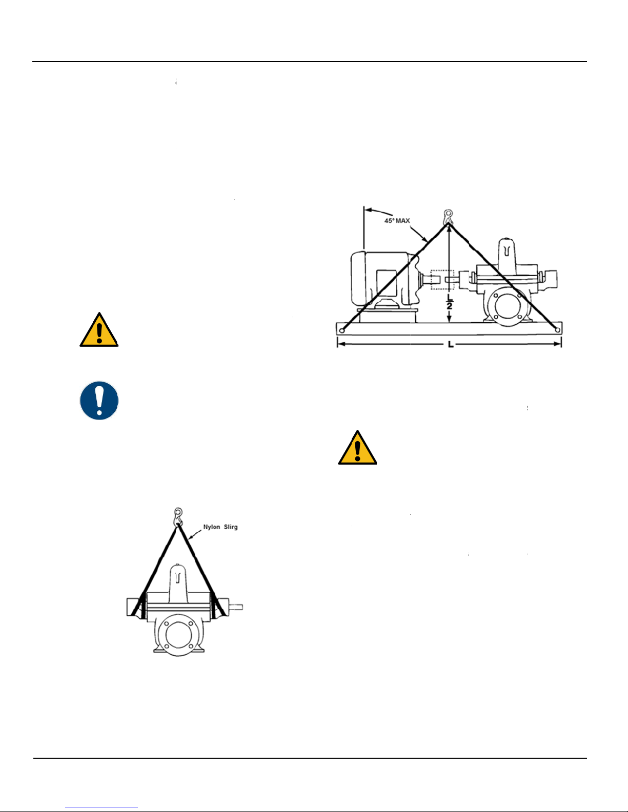
are Shaft P
u
h
aft pump shoul
d
o
n sling around
choker hitches.
Fig. 1 How t
o
m
p
a
ndling, a
the factory in
a
s
port by fork-lift
t
p
t, check the pu
m
age has happe
n
ally shipped fro
m
r
ts and accesso
r
t
ainer and shipp
e
d
, promptly notif
y
es must be suff
i
e
used by autho
lifting lugs, if pr
o
e
components t
o
o
not stand und
e
oads. A failure
i
g
ging can result
u
ry or death, or
l
l packing materi
a
g
ulations.
u
mp (Model
d
be lifted as sh
both bearing s
u
o
lift a Model 1
0
nd
a
container
t
ruck or a
mp visually to
n
ed during
m
the factory
r
ies can be
e
d with the pum
p
y
the carrier’s
i
ciently strong a
rized personnel
o
vided, are onl
y
o
which they are
e
rneath
i
n the lifting
in serious
property dama
g
a
ls in accordanc
e
100)
own in Fig. 1.
pports using
0
0
p
nd
.
y
g
e.
e
5.2.
2
5.2.
2
Larg
e
ends
the h
o
the p
o
base.
hook
s
will b
e
5.2.
2
Pum
p
show
n
housi
n
the m
Make
cond
u
place
positi
o
2
Comple
t
2
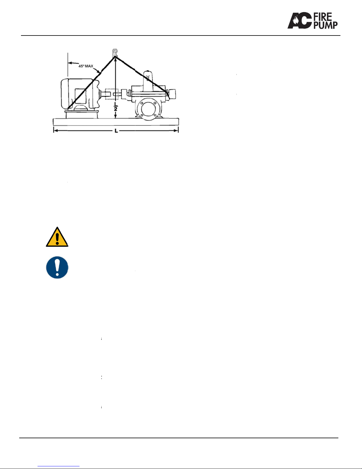
.1 Bases su
e
bases are sup
p
of the base, as
s
o
les provided in
t
o
ints of the hook
s
Attach nylon sli
n
s
. Size the equip
m
e
less than 45° f
r
Fig. 2 How to
2
.2 Bases su
WAR
N
Do n
o
casin
g
p
units supplied
w
n in Fig. 3. Plac
e
ng. Place the re
m
m
oto
r
as close to
t
e
sure the sling d
o
u
it box. Join the
f
over the lifting
h
o
ning the sling u
t
e Pump uni
t
u
pplied with li
p
lied with lifting h
s
hown in Fig. 2.
P
t
he four corners
s
do not touch t
h
n
gs, chains, or
w
ment for the loa
d
r
om the vertical.
lift a Model 150
M
u
pplied witho
u
N
ING
o
t use the lugs
o
g
to lift the pum
p
w
ith bases witho
e
one sling arou
n
m
aining sling ar
o
the mounting fe
e
o
es not damage
f
ree ends of the
s
h
ook. Use extre
m
nder the motor
s
A
t
(Model 15
0
fting holes
oles in the sides
P
lace lifting hoo
k
of the base. Be
s
h
e bottom of the
p
w
i
r
e rope to the li
f
d
, so that the lift
a
M
pump unit larg
e
u
t lifting hole
s
o
n the pump up
p
p
unit.
ut lifting holes,
a
n
d the outboard
b
o
und the back e
n
e
t as possible.
the housing cov
s
lings together a
n
m
e care when
s
o it cannot slip o
A
C6102 Rev 03
0
M)
or the
k
s in
s
ure
p
ump
f
ting
a
ngle
e
base
s
p
er
a
s
b
earing
n
d of
er or
nd
o
ff.
AC61
0
0
2 Rev 03
Fig.
3
5.2.3 E
1
5
Before liftin
manufactur
e
5.3
S
5.3.1 T
If the pump
arrival, stor
e
changes in
covers in pl
of the pum
p
Shaft exten
should be
c
preventativ
e
Rotate the
p
the bearing
s
corrosion,
a
5.3.2 L
Storage lon
g
storage. Fol
with the foll
o
Remove th
e
Apply a corr
Corporation
3
How to lift a M
o
ngine drive
n
5
0E)
g
engine driven
e
r’s instructions
S
torage
CAUTION
Damage du
e
corrosion a
n
unit.
NOTICE
For special
p
engines, an
d
manufacture
storage proc
e
emporary S
t
is not to be ins
t
e
it in a clean, d
ambient tempe
r
ace to keep dirt
p
casing.
sions and other
oated with an e
a
e
such as Valvo
p
ump shaft 10-1
s
with lubricant
a
nd to prevent f
a
ong Term S
t
g
er than six mon
low the same pr
o
o
wing additions.
gland and the p
a
o
sion inhibiting
o
VpCI-329, to th
e
o
del 150M pum
p
n
pump unit
pump unit, refe
.
e
to dirt and hu
m
n
d contaminatio
n
p
rotection of elec
t
d
couplers, refer
t
r’s instruction fo
r
e
dures.
t
orage
t
alled and oper
a
ry place having
r
ature. Leave pi
p
and other forei
g
exposed machi
a
sily removable
line Tectyl 502-
C
5 times twice a
and to retard o
x
a
lse brinelling o
f
t
orage
t
hs is considere
d
o
cedu
r
e for tem
p
a
cking from the
s
o
il soluble produ
c
e
interior of the p
u
p
unit large bas
e
s
(Model
r to the engine
m
idity resulting i
n
of the pump
t
ric motors, dies
e
t
o the
r
their long term
a
ted soon after
slow moderate
p
ing connection
g
n material out
ne surfaces
rust
C
.
month to coat
x
idation,
f
the bearings.
d
long term
p
ora
r
y storage
s
tuffing box.
c
t such as Corte
c
u
mp casing and
e
n
e
l
c
the st
the m
Seal
t
Add 1
seal
a
seals
.
Rotat
e
mont
h
t
uffing box. [Pre
p
m
anufacturer’s in
s
t
he end of the st
u
1
/2oz [14g] of Co
a
ll vents and app
.
e the pump shaf
t
h
s to prevent the
p
are the corrosio
n
s
tructions].
u
ffing box with w
a
o
rtec VpCI-329 t
o
p
ly waterproof ta
p
t
10-15 turns tim
e
e
shaft from seizi
n
n
inhibiting soluti
o
aterproof tape
o
the bearing fra
m
p
e around the gr
e
e
s at least every
n
g up.
12
o
n per
m
es,
e
ase
three
Serie
s
13
s
8100/8150/820
6
D
6.1
G
The horizo
n
stage [seri
e
8200] non
s
6.2
D
The fire pu
m
on the nam
e
represents:
Code
H
10
8
17
F-S
Ta
b
6.3
N
6.3.1 P
The namep
attached to
referenced
used to ord
e
digit of the
s
orders of m
0/9100 Fire Pu
m
D
escriptio
n
G
eneral
n
tal split case c
e
e
s 8100, 8150,
a
s
elf-priming pu
m
D
esignatio
n
m
p can be ident
e
plate; for exa
m
Description
No prefix=Ca
H=Ductile iro
n
Suction inlet
s
Discharge ou
Nominal imp
e
S-small, M-m
capacity imp
e
b
le 2 Key for s
N
ameplate
ump name
p
l
ate shows all i
m
the upper casi
n
by the serial nu
m
e
r all spare and
s
erial number i
n
ore than one p
u
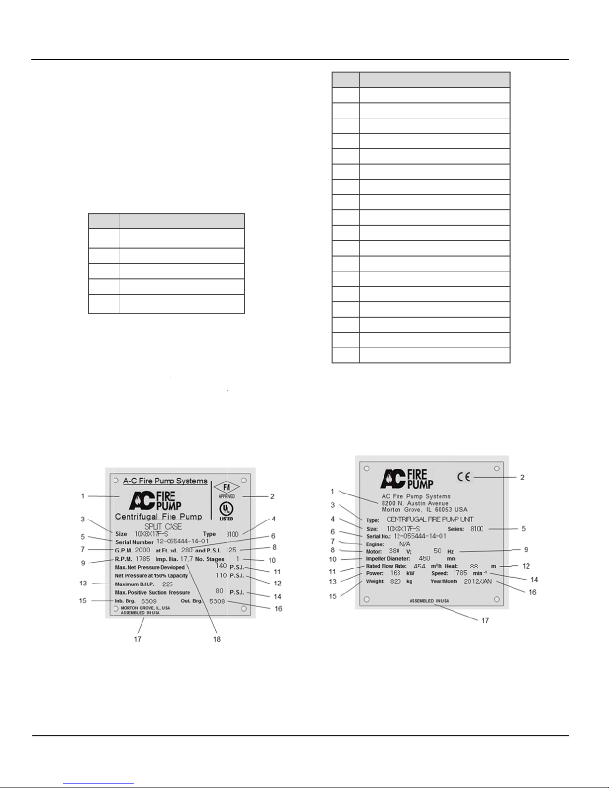
Fig. 4 Name
p
m
p
n
e
ntrifugal fire pu
a
nd 9100] and t
w
m
p.
n
i
fied by size de
s
m
ple, H10 X 8 X
st iron A48;
n
A536
s
ize ANSI
tlet size ANSI
e
ller diamete
r
edium, L-large
e
lle
r
ize designation
p
late
m
portant data o
f
n
g. Records for
t
m
ber and it mu
s
replacement p
a
n
dicates the spe
c
u
mp].
p
late of a Fire p
u
mp is a single
w
o stage [series
s
ignation stated
17F-S
f
the pump. It is
t
he pump are
s
t, therefore, be
a
rts. [The last
c
ific pump on
u
mp
I
t
6.3.
2
The
n
It is
a
t
em Descript
i
1 Manufact
2 Approval
3 Size
4 Model Ty
5 Serial nu
m
6 Head [fe
e
7 Rated flo
w
8 Rated pr
e
9 Speed [
R
10 Number
o
11 Net pres
s
12 Net pres
s
13 Maximu
m
14 Maximu
m
15 Inboard
b
16 Outboard
17 Country
o
18 Impeller
d
Table 3 N
a
2
Pump u
n
n
ameplate sho
w
a
ttached to the
u
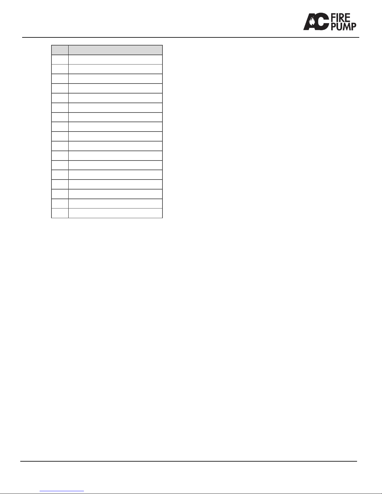
Fig. 5 N
a
i
on
ure
r
Agencies
pe
m
be
r
e
t]
w
rate [GPM]
e
ssure [psi]
R
PM]
o
f stages
s
ure developed [
p
s
ure at 150% of
f
m
power [BHP]
m
suction pressu
r
b
earing numbe
r
bearing numbe
r
o
f origin
d
iameter [in]
a
meplate of a F
i
n
it namepla
t
w
s all important
d
u
pper casing.
a
meplate of a Fi
A
p
si]
f
low [psi]
r
e [psi]
r
i
re-pump
t
e
d
ata of the pum
p
re pump unit
A
C6102 Rev 03
p
unit.
AC6102 Rev 03 14
Item Description
1 Manufacturer
2 CE Mark
3 Type
4 Pump Size
5 Model series
6 Serial number
7 Engine type [engine driven pump units]
8 Motor voltage
9 Frequency
10 Impeller diameter [mm]
11 Rated flow rate [m3/hr]
12 Head [m]
13 Power [kW]
14 Speed [RPM]
15 Pump unit weight [kg]
16 Date of manufacture
17 Country of origin
Table 4 Nameplate of a Fire pump unit
6.4 Design detail
6.4.1 Casing
The pump casing is made from Cast Iron or Ductile Iron,
and is an axially-split double suction volute design with the
suction and discharge flanges and mounting feet cast
integrally with the lower casing half.
Tapped and plugged holes are provided for priming, vent,
drain, and gauge connections. The upper casing half can
be removed without disturbing the suction or discharge
piping. Pump flanges are made with ANSI Class 125 or
250 drillings, and come in the following combinations,
[Suction/Discharge]: 125/125; 125/250; and 250/250.
The suction and discharge are on a common centerline in
the vertical direction for all pump model types; and on a
common horizontal centerline for model types 8100, 8150,
and 9100.
6.4.2 Impeller
The impeller is an enclosed double suction type made of
bronze, which is statically and hydraulically balanced. The
impeller is firmly secured to the shaft by a key positioned
by shaft sleeves and both locked in place by shaft sleeve
lock nuts.
6.4.3 Shaft
The shaft is made of AISI 1045 or 4140 steel and of ample
size to operate under load with a minimum deflection.
6.4.4 Shaft sleeves
The shaft sleeves are made of bronze and protect the
shaft from wear and from contact with the pumped liquid.
Shaft sleeves are locked in place by threaded bronze
shaft sleeve nuts. An O-ring is furnished under the sleeve
to prevent leakage.
6.4.5 Stuffing Box
The stuffing box consists of die formed, graphite coated,
synthetic fiber packing rings; and a split type gland to
permit removal and access to the packing. The 8100
stuffing box housing is made of cast iron, and is separate
from the pump casing. The stuffing box housing is drilled
and tapped for drain connections.
6.4.6 Casing Rings
The casing rings are made of bronze and are installed
with an anti-rotation device and designed to restrict
leakage across the ring fit.
6.4.7 Bearings
The bearings are grease lubricated rolling type selected to
carry radial and thrust loads. The outboard bearing is
retained to handle the axial thrust.
6.4.8 Bearing Housings
The bearing housings are bolted to the pump and are
piloted to positive alignment of the rotating element. The
housings provide a fit for the inboard bearing that allows
freedom for thermal expansion while the outboard
bearing(s) are clamped in place in order to take all the
thrust loads and keep the rotating element in its proper
axial location. Openings for adding grease and draining
grease are provided.
6.4.9 Baseplate
The baseplate is welded construction, manufactured from
steel and is sufficiently rigid to support the pump and the
driver.
6.4.10 Coupling
The coupling is of the flexible type. The coupling hubs are
secured to the driver and the driven shafts by a setscrew
located over the key.
6.4.11 Coupling Guard
The coupling guard is made of metal, and meets the
requirements of EN ISO 13857.
6.4.12 Rotation
Pumps have a clockwise or counterclockwise rotation
when viewed from its driven end.

Series 8100/8150/8200/9100 Fire Pump
15 AC6102 Rev 03
6.5 Noise characteristics
The maximum measured A-weighted sound pressure level
[LpA] for the pump and motor, measured at a distance of
3.3 ft. [1m] from the pump, under full load, in accordance
with EN ISO 3746 is 90dB.
The maximum measured A-weighted sound pressure level
[LpA] for the pump and diesel engine, measured at a
distance of 3.3 ft. [1m] from the pump, under full load, in
accordance with EN ISO 3746 is 106dB.
6.6 Scope of supply
The pump unit includes the following items:
Pump
Driver, (motor or engine)
Baseplate
Coupling
Coupling guard
6.7 Dimensions and weights
Refer to the general dimensional drawing supplied with
the pump unit
7 Installation
This section describes the installation of a complete
pump unit.
CAUTION
Installations should be performed by persons
qualified in the setting up of pumping
equipment.
WARNING
All electrical work should be carried out by
qualified personnel.
7.1 Location
WARNING
Engine-driven pump units:
The engine must be provided with adequate
ventilation to satisfy the requirements of the
combustion system, and allow adequate
dissipation of radiated heat and exhaust
emissions.
Install the pump in a well-ventilated, dry place above the floor
level wherever possible. Take care to prevent the pump from
freezing during cold weather when not in operation.
The pump should be installed with sufficient space around it
to facilitate ventilation and accessibility for inspection,
maintenance and service. A clear space with ample head
room should be allowed for the use of an overhead crane or
hoist to lift the unit.
Install the pump as near to the suction supply as possible,
with the shortest and most direct suction pipe practical. The
total dynamic suction lift (static lift plus friction losses in
suction line) should not exceed the limits for which the pump
was sold.
When installing the pump, consider its location in relation to
the system to assure that sufficient Net Positive Suction Head
[NPSH] is available at the pump inlet connection. Available
NPSH [NPSHA] must always equal or exceed the required
NPSH [NPSHR] of the pump.
The pump must be primed before starting. Whenever
possible, the pump should be located below the fluid level to
assure priming. This condition provides a positive suction
head on the pump. It is also possible to prime the pump by
pressurizing the suction vessel.
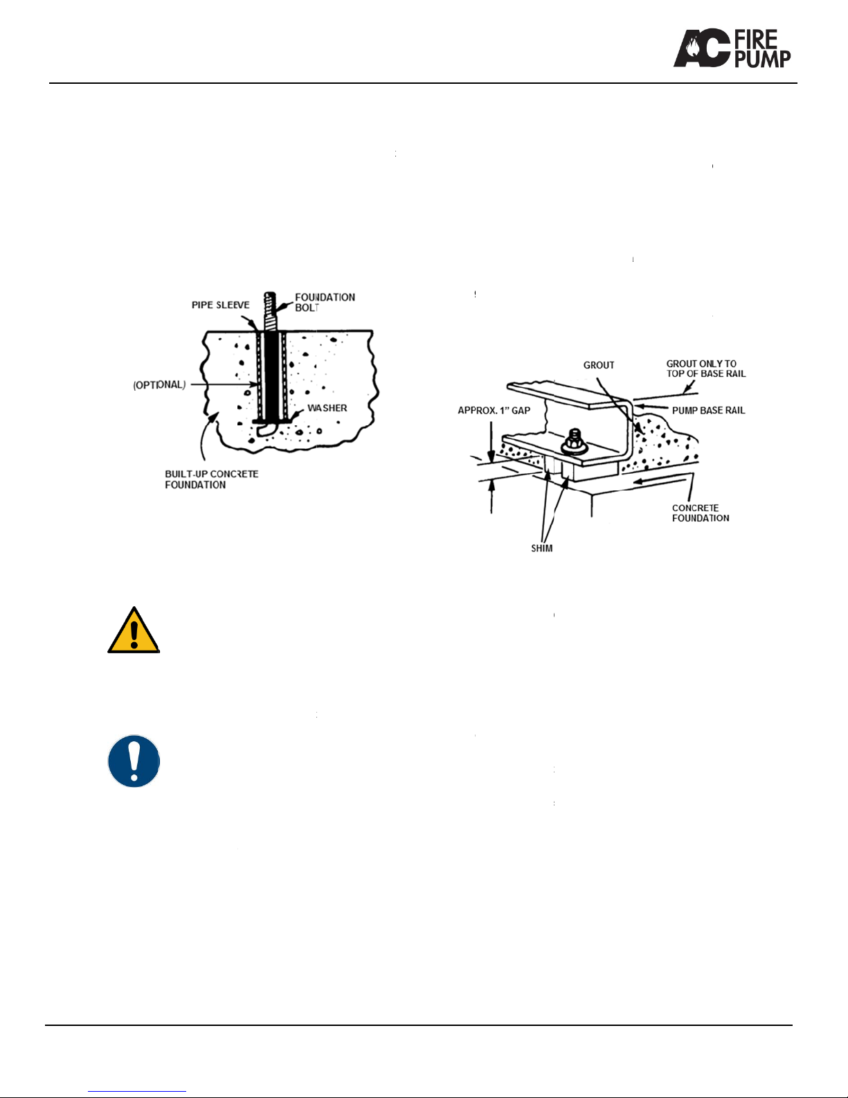
7.2 Foundation
We recommend that the pump unit should be installed on a
concrete foundation, sufficiently substantial to absorb
vibration and to form a permanent, rigid support for the
baseplate.
A base of concrete weighing 3 to 5 times the weight of the
pump unit is recommended.
The foundation should be 3 to 6 inches [75 to 150mm] longer
and wider than that of the baseplate that will be installed.
Foundation bolts must match those of the base plate. The
foundation should be poured without interruption to within 1/2
to 1-1/2 inches [12.7 to 38.1mm] of the finished height. The
top surface of the foundation should be well scored and
AC61
0
0
2 Rev 03
grooved be
f
surface for t
h
Foundation
6. An option
the top of th
e
alignment t
o
bolt length f
o
washers. T
h
several day
s
In installati
o
particularly
mass of at
l
7.3
L
Use blocks
a
anchor bolt
s
baseplate a
p
foundation,
w
plate, as sh
o
By adding o
plumb the p
u
have to be l
e
Draw ancho
motor shaft
s
o
re the concrete
h
e grout.
bolts should be
s
al 4 inch [102m
m
e
concrete will a
l
o
match the hole
s
o
r grout, shims, l
o
h
e foundation sh
o
s
before the bas
e
o
ns where lower
important, we r
e
l
east 5 times th
a
Fig. 6
L
eveling the
WARNING
Lifting devic
e
must only b
e
Eyebolts or l
lifting the co
m
attached. D
o
loads. A fail
u
can result in
or property
d
NOTICE
This proced
u
foundation h
a
hold down b
o
the pump un
pump and d
r
aligned at th
e
mounted, co
n
recommend
a
assume res
p
a
nd shims unde
r
s
and midway be
t
p
proximately 1 i
n
w
ith studs exten
d
o
wn in Fig. 7.
r
removing shim
s
u
mp shaft and fl
a
e
vel.
r
nuts tight agai
n
s
or coupling hub
sets; this provid
e
s
et in concrete a
s
m
] long sleeve ar
o
low some flexibi
l
s
in the base plat
o
wer base plate
o
uld be allowed
t
e
plate is shimm
e
sound and vibr
a
e
commend a fo
u
a
t of the compl
e
Foundation
baseplate
e
s must be suffi
c
e
used by author
i
ifting lugs, if pro
v
m
ponents to whi
c
o
not stand unde
r
u
re in the lifting
d
serious person
a
d
amage.
u
re assumes tha
t
a
s been prepare
d
o
lts extending u
p
i
t. It must be un
d
r
iver have been
m
e
factory. If the d
n
sult AC Fire Pu
m
a
tions. AC Fire P
p
onsibility for fina
r
the baseplate f
o
t
ween bolts, so
a
n
ch [25.4mm] ab
o
d
ing through hol
e
s
under the bas
e
a
nges. The base
n
st base, and ob
s
s for alignment.
(
e
s a bonding
s
shown in Fig.
o
und the bolts a
t
l
ity in bolt
e. Allow enough
flange, nuts and
t
o cure for
e
d and grouted.
a
tion levels are
u
ndation with a
e
te pump unit.
c
iently strong an
d
i
zed persons.
v
ided, are only f
o
c
h they are
r
neath suspend
e
d
evice or rigging
a
l injury or death,
t
a concrete
d
with anchor or
p
ready to receiv
e
erstood that the
m
ounted and rou
g
river is to be fiel
d
m
p for
ump cannot
l alignment.
o
r support at the
a
s to position the
o
ve the concrete
e
s in the base
e
, level and
p
late does not
s
erve pump and
(
Temporarily
t
d
o
r
e
d
e
g
h
d
remo
v
chec
k
If alig
n
appr
o
retigh
align
m
align
m
NOT
E
mutu
a
facilit
y
Chec
k
pum
p
Pour
g
Grou
t
pipin
g
grouti
7.4
Grou
t
weig
h
appr
o
unit,
(
Build
grout
.
and t
h
be co
After
t
found
align
m
Appr
o
when
to th
e
from
c
v
e coupling gua
r
k
ing alignment.)
nment needs im
p
o
priate positions
h
tening of the an
c
m
ent. Repeat thi
s
m
ent” is reached
E
: Reasonable a
a
lly agreed upon
y
(final operator)
.
k to make sure t
h
p
flanges without
grout in the bas
e
t
ing) and allow g
r
g
to pump. (24 h
o
i
ng procedure.)
Fig.
7
Groutin
g
t
compensates f
o
h
t of the pump u
n
o
ved, non-shrinki
(
see Fig. 7).
a strong form ar
o
.
Soak the top of
h
en remove any
o
mpletely filled wi
the grout has th
o
d
ation bolts and t
m
ent after the fo
u
o
ximately 14 day
s
the grout has th
e
exposed edges
c
oming in conta
c
r
d, see section 8
p
rovement, add
s
under the basep
c
hor nuts will shi
f
s
procedure until
.
lignment is defin
e
by pump contra
.
h
at the piping c
a
placing pipe str
a
e
plate completel
rout to dry thoro
u
o
u
r
s is sufficient
7
Leveling of pu
m
g
or
uneven found
a
n
it, and prevents
ng grout, after s
e
o
und the founda
t
the concrete fo
u
surface water. T
i
th grout.
o
roughly harden
e
t
ighten if necess
a
u
ndation bolts ar
e
s after the grout
h
oroughly dried,
a
of the grout to p
c
t with the grout.
.2 Coupling Gua
s
hims or wedge
s
late, so that
f
t the shafts into
c
a “reasonable
e
d as that which
ctor and the acc
e
a
n be aligned to t
h
a
in on either flan
g
y (see section 7
.
u
ghly before atta
time with appro
v
m
p unit
a
tion, distributes
shifting. Use an
e
tting and levelin
t
ion to contain th
u
ndation thoroug
h
he base plate s
h
e
d, check the
a
ry. Check the
e
tightened.
has been poure
d
a
pply an oil base
revent air and m
16
rd, for
s
at
closer
is
e
pting
he
g
e.
.
4
ching
v
ed
the
g the
e
h
l
y
,
h
ould
d
or
paint
oisture
Serie
s
17
s
8100/8150/820
7.5 I
n
When a co
m
the
factory,
means of
s
h
The pump/
d
transport a
n
parallel, or
a
vertical plan
Proper align
This should
set and gro
u
Alignment s
h
driver only
u
recommend
temperatur
e
All measure
m
foot bolts tig
There are t
w
flexible cou
p
are not par
a
are parallel
There are t
h
misalignme
n
1.
2.
3.
0/9100 Fire Pu
m
n
itial Align
m
WARNING
Disconnect
a
performing
a
instructions
injury.
NOTICE
The alignme
motor driven
for Engine-d
r
the Engine
m
WARNING
Replace co
u
alignment.
F
could result
CAUTION
Misalignmen
and bearing
bearing failu
r
NOTICE
Alignment s
h
the pipes; if
n
the pump, a
n
driver.
NOTICE
Read Coupli
n
supplied wit
h
perform alig
n
m
plete pump uni
the coupling ha
s
h
ims inserted u
n
d
river could hav
e
n
d installation.
M
a
combination of
t
e
s.
ment is essentia
be performed af
t
u
t has dried thor
o
h
ould be made
b
u
ntil the coupling
ed tolerances, a
s under normal
c
m
ents should be
htened.
w
o types of misa
l
p
lings: angular
m
a
llel, and parallel
b
ut not on the s
a
h
ree methods co
m
n
t:
Straight edg
e
Dial indicato
r
Laser Align
m
manufacture
r
m
p
m
ent
a
nd lock out po
w
a
lignment. Failu
r
could result in
s
nt procedures th
a
pump units. Ali
g
r
iven pump units
m
anufacturer’s In
u
pler guard afte
r
F
ailure to follow
in serious pers
o
t causes excess
i
l
oads that result
r
e and ultimate s
e
h
ould be made b
e
n
ot, it may not b
e
n
d it will be diffic
u
n
g Manufacturer
h
the pump unit
b
n
ment.
t comes pre-as
s
s
been accurat
e
n
der the pump a
n
e
become misali
g
M
isalignment can
t
hese, and in th
e
l for correct pum
t
er base plate h
a
o
ughly according
b
y moving and s
h
hubs are within
n
d should be m
a
c
onditions.
taken with the
p
l
ignment encoun
m
isalignment, in
w
misalignment,
w
a
me axis.
m
monly used to
e
and calipers.
r
m
ent Equipment (
r
’s instructions f
o
w
er before
r
e to follow the
s
s
erious persona
l
a
t follow are for
g
nment procedur
e
are available in
stallation Manua
r
performing
these instructio
n
o
nal injury.
i
ve wear, vibrati
o
in premature
e
izing of the pu
m
e
fore connecting
e
possible to mo
v
u
lt to move the
instructions
b
efore attempting
s
embled from
e
ly aligned by
n
d driver.
g
ned during
be angular,
e
horizontal and
p operation.
a
s been properly
to instructions.
h
imming the
the
a
de at operating
ump and driver
tered with
w
hich the shafts
w
here the shafts
determine
see
o
r use).
s
e
l
e
s
l.
n
s
o
n,
m
p.
v
e
to
7.5.
1
The
m
calip
e
dial i
n
7.5.1
With
c
gap
b
shim
e
the h
u
(see
F
7.5.1
With
c
the ri
m
vertic
a
equip
rims,
v
manu
7.5.
2
The
d
accu
r
guide
1
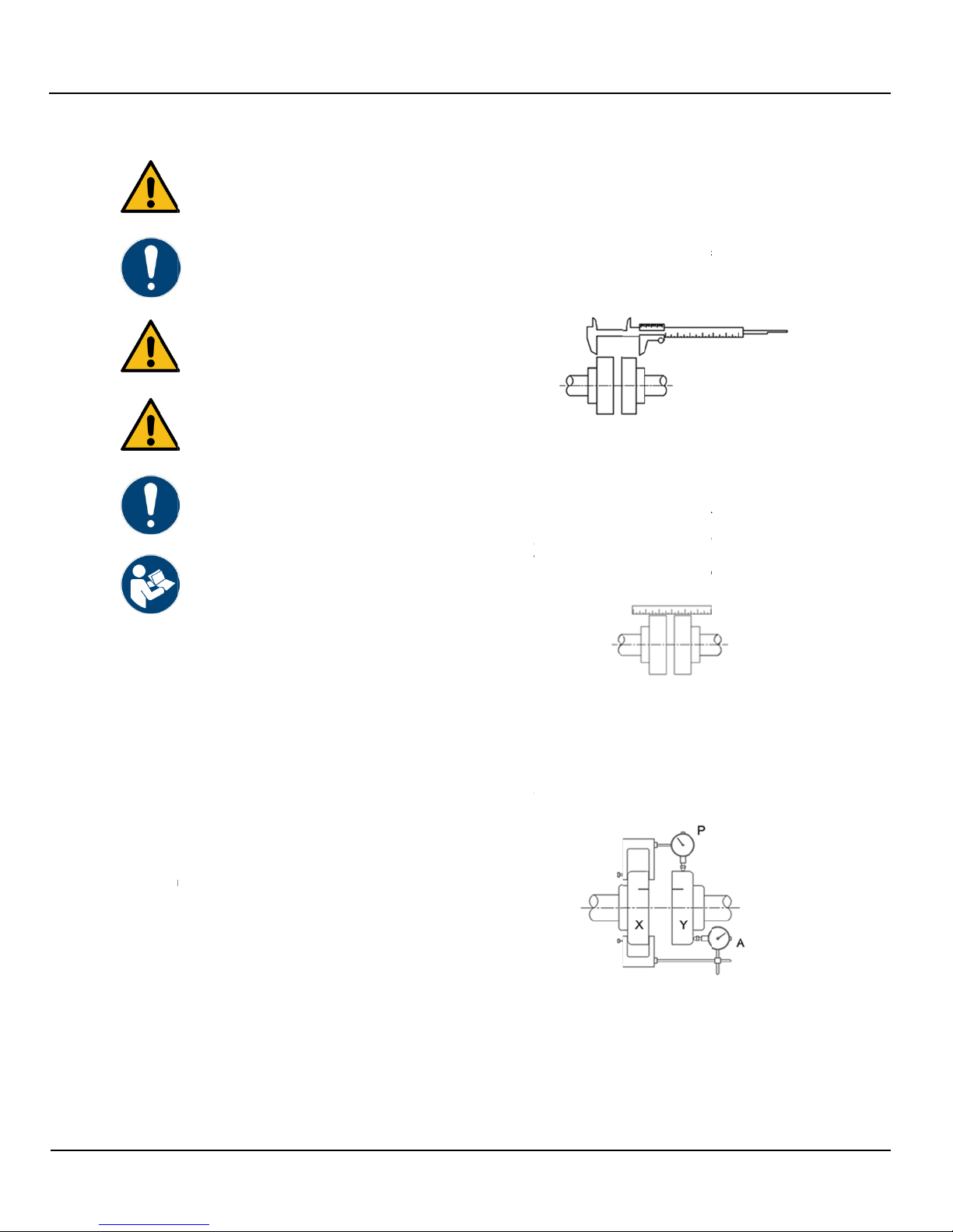
Straight
e
m
ost simple alig
n
e
rs. This method
n
dicator or laser i
.1
A
ngular
A
c
oupling hubs st
a
b
etween the cou
p
equipment until
t
u
bs are within th
e
F
ig. 8).
Fig. 8 A
n
.2 Parallel
A
c
oupling hubs st
a
m
of the couplin
g
al and horizontal
p
ment until the st
r
vertical and hori
z
u
facturer’s guidel
i
Fig
2
Dial indi
c
d
ial indicator sho
u
r
acy is required.
C
e
line for accepta
b
F
e
dge metho
d
n
ment check is w
is the least acc
u
i
s not available.
A
lignment
a
tionary, use cal
i
p
ling hubs at 90°
t
he gap differen
c
e
coupler manuf
a
n
gular Alignment
A
lignment
a
tionary, lay stra
g
hub at 90° inte
r
l
alignment offse
t
r
aight edge lies f
z
ontal. Check th
e
ine for permissib
g
. 9 Parallel Align
c
ator metho
d
u
ld be used whe
n
C
heck the coupl
e
b
le alignment tol
e
ig. 10 Dial Indic
a
A
d
of alignme
n
ith a straight ed
g
u
rate, but will ser
v
i
pers to measur
e
intervals. Adjust
c
e at all points ar
o
a
cturers guidelin
e
ight edge flat ag
a
r
vals to determin
e
t
s. Adjust and/or
f
lat against both
h
e
coupler
b
le gap, (see Fig.
ment
d
of alignme
n
n
greater alignm
e
e
r manufacturer’
s
e
rances.
a
to
r
A
C6102 Rev 03
n
t
g
e and
v
e if a
e
the
and/or
o
und
e
s,
a
inst
e
shim
h
ub
9).
n
t
e
nt
s

AC61
0
0
2 Rev 03
7.5.2.1
A
To check a
n
coupling hal
f
face of the
o
both couplin
rotate both
c
match; ens
u
the same s
p
for accepta
b
7.5.2.2 P
To check p
a
coupling hal
f
outside dia
m
10). Set the
so that the i
n
button alwa
y
manufactur
e
7.5.3
A
The followin
alignment o
f
Protection
P
Couplings.
Alignment i
s
which has b
e
applications
dial indicato
r
7.5.3.1
M
Clean all m
e
seals lightly
place on sh
a
mount hubs
Reposition
h
specified in
t
should be a
p
the setscre
w
7.5.3.2
G
Use a spac
e
Table 5. Ins
e
intervals an
d
face with fe
e
maximum
m
installation l
i
7.5.3.3 P
Align so tha
t
limits specifi
also at 90° i
n
The clearan
c
A
ngular Align
m
n
gular alignment,
f
(X), and positio
o
pposite couplin
g
g hubs as show
n
c
oupling halves t
o
u
ring that the indi
c
p
ot. Check the c
o
b
le alignment tol
e
a
rallel Align
m
a
rallel alignment,
f
(X), and positio
m
eter of the opp
o
dial to zero, rota
t
n
dex lines match
y
s indicates off t
h
e
r’s guideline for
A
lignment of
g
procedure is i
n
f
Rexnord Indust
r
P
roducts, Inc., Ty
p
s
shown using a
s
e
en prove to be
a
.
However, for s
u
r
s is recommend
M
ount Seal an
d
e
tal parts using n
with coupling m
a
a
fts before moun
with flange face
s
h
ubs on shafts a
s
t
able 5. The len
g
p
proximately eq
u
w
s.
G
ap and Angul
e
r bar equal to th
e
rt bar, as show
n
d
measure clear
a
e
ler gage. The di
f
m
easurements m
u
mits specified in
Fig. 11 U
s
a
rallel Offset
A
t
a straight edge
ed in Table 5 on
n
tervals, (see Fi
g
c
e must not exc
e
m
ent
mount dial indic
a
n the dial indicat
o
g
half (Y). Scribe
n
in Fig. 10. Set
t
o
gether, so that
t
c
ator button alw
a
o
upler manufactu
e
rances.
m
ent
mount dial indic
a
n the dial indicat
o
o
site coupling hal
f
t
e both coupling
; ensuring that t
h
h
e same spot. C
h
acceptable align
g
rid couplin
g
n
tended for mou
n
r
ies, LLC and Cl
a
p
e T10 Close C
o
s
pacer bar and s
t
a
ccurate for ma
n
u
perior final align
ed, per 7.5.2.
d
Hubs
on-flammable s
o
a
nufacturer supp
ting shaft hubs. I
s
flush with the s
s
required achie
v
g
th of engageme
n
u
al to the shaft di
a
ar Alignment
(
i
ckness to the g
a
n
above to the s
a
a
nce between th
e
f
ference in mini
m
u
st not exceed t
h
Table 5.
s
ing Spacer Ba
r
A
lignment (P)
rests squarely, (
o
both hubs as sh
g
. 12). Check wit
h
e
ed the Parallel
O
a
tor (A) to the
o
rs button on th
e
index lines on
he dial to zero,
t
he index lines
a
ys indicates off
rer’s guideline
a
tor (P) to the
o
rs button on th
e
f
(Y), (see Fig.
halves together,
h
e indicator
h
eck the coupler
ment tolerances
.
g
s
n
ting and
a
rke Fire
o
upled Grid
t
raight edge,
n
y industrial
ment, the use of
o
lvent. Coat the
lied grease and
nstall keys and
haft ends.
v
ing the hub gap
n
t on each shaft
a
meter. Tighten
(
X-Y)
a
p specified in
a
me depth at 90°
e
bar and hub
m
um and
h
e angular
o
r within the
own above and
h
feeler gages.
O
ffset installation
e
e
.
limits
If adj
u
remo
v
align
t
of th
e
Tight
e
in all
d
until t
h
7.5.
3
Com
p
suppl
furnis
ends
will e
n
halve
s
Spre
a
seat
w
7.5.
3
Com
p
with
a
with t
o
groo
v
cove
r
on th
e
faste
n
specified in Tab
l
u
stment is need
e
v
e an equal amo
t
he height. To c
o
e
motor foot with
a
e
n the motor bol
t
d
irections, if a c
o
he desired resul
t
Fig.
3
.4 Insert Gri
d
p
letely pack gap
a
ied grease befor
e
hed in two or m
o
extend in the sa
m
n
sure correct gri
d
s.
Fi
g
a
d the grid slightl
w
ith a soft mallet
Fi
g
3
.5 Pack wit
h
p
letely pack the
s
a
s much grease
a
o
p of the grid. P
o
v
es in the cover.
P
r
half and assem
b
e
same side, (se
e
n
ers tightening t
o
l
e 5.
e
d, loosen the m
o
o
unt of shims un
d
o
rrect side misali
g
a mallet.
t
s and check ag
a
o
rrection is mad
e
t
is obtained.
12 Using Straig
h
d
and grooves wit
h
r
e inserting grid.
W
o
re segments, in
s
m
e direction as
s
d
contact with n
o
g
. 13 Grids mag
n
y to pass over t
h
, (see Fig. 14).
g
. 14 Seating th
e
h
grease and
a
s
paces between
a
s possible and
w
o
sition seals on
h
Position gaskets
b
le covers so th
a
e
Fig. 15). Secu
r
o
torque specifie
d
o
tor bolts and ad
d
d
er each motor f
o
g
nment, strike th
a
in. Re-check ali
g
e
. Repeat the pro
h
t edge
h
coupling manu
f
W
hen grids are
s
tall them so tha
t
s
hown in Fig. 13.
o
n-rotating pin in
n
ified
h
e coupling teeth
e
grid
a
ssemble cov
e
and around the
g
w
ipe off excess f
h
ubs to line up w
i
on flange of low
a
t the match mar
k
r
e cover halves
w
d
in Table 5.
18
d
or
o
ot to
e side
g
nment
cess
f
acturer
t
all cut
This
cover
and
e
rs
g
rid
f
lush
i
th the
w
er
k
s are
w
ith

Serie
s
19
s
8100/8150/820
Size
P
O
M
A
IN
C
1040T 0.0
1050T 0.0
1060T 0.0
1070T 0.0
1080T 0.0
0/9100 Fire Pu
m
Fig. 15 Cove
r
WARNING
Do not oper
a
lubrication.
CAUTION
Ensure that
t
cover.
Fig. 16 Misalig
n
Insta
l
P
arallel
O
ffset (P) An
g
(
x
X
C
H
MAX
mm
MAX
INCH
1 0.15 0
1 0.20 0
1 0.20 0.01
1 0.20 0.01
1 0.20 0.01
Table 5 Misal
m
p
r
installation
a
te coupling wit
h
t
he lube plugs ar
e
n
ment and End
F
l
lation Limits
g
ular
x
-y) Hub G
a
± 10
%
MAX
mm
MAX
INCH
0.08 0.13
0.10 0.13
0.13 0.13
0.13 0.13
0.15 0.13
ignment and En
d
h
out proper
e
installed in the
F
loat
a
p
%
End Float
(Min) 2 x
F
MAX
mm
MAX
INCH
M
A
m
m
3 0.21 5.
3
3 0.21 5.
3
3 0.26 6.
5
3 0.26 6.
5
3 0.29 7.
3
d
float
F
A
X
m
3
6
3
8
5
5
5
8
3
2
7.6
7.6.
1
Whe
n
follo
w
1.
P
2.
D
a
3.
U
i
4.
W
t
c
5.
I
s
d
6.
I
u
r
7.
M
8.
W
d
9.
R
Maxi
m
vary
w
force
s
misal
i
prem
a
1.
P
2.
N
3.
A
p
s
a
4.
D
a
f
t
e
The t
a
mom
e
Horiz
o
SIZE
F
Ti
T
in.
l
1040T 10
1050T 20
1060T 20
1070T 20
1080T 20
Pipe co
n
CAU
T
Do n
o
at the
strain
pump
dama
1
Suction
a
precauti
o
n
installing the p
u
w
ing precautions:
P
iping should al
w
D
o not move pu
m
a
lignment impos
s
U
se pipe hange
r
i
ntervals to provi
W
hen expansio
n
t
hey must be ins
t
c
losest to the pu
m
I
t is usually advi
s
s
uction and disc
h
d
ecrease the los
I
nstall piping as
s
u
nnecessary be
n
r
adius 90° fitting
s
M
ake sure that
a
W
he
r
e flanged
jo
d
iamete
r
s match
R
emove burrs a
n
m
um forces and
w
ith the pump si
z
s
and moments
t
ignment, hot be
a
a
ture pump failu
r
P
revent excessi
v
N
ever “spring” pi
A
nchor indepen
d
p
iping near the
p
s
train is transmit
t
a
re tightened.
D
o not install ex
p
a
ny way that wo
u
fr
om system pre
s
t
ie bolts and spa
c
e
xpansion joints
a
bles in 7.6.2 su
e
nts allowed on
8
o
ntal Split Case
Cover
F
astener
ghtening
Torque
Maxim
u
Allowa
Spee
(rpm
lb Nm
0
0 11.3 360
0
0
0 22.6 360
0
0
0 22.6 360
0
0
0 22.6 180
0
0
0 22.6 180
0
Table 5 Conti
n
n
nections
T
ION
o
t draw piping in
flanged conne
c
adversely affe
c
, which could r
e
ge.
a
nd dischar
g
o
ns
u
mp piping, be s
u
w
a
y
s be run to t
h
m
p to pipe. This
c
s
ible.
r
s or other supp
o
de support.
n
joints are used
t
alled beyond th
e
mp.
s
able to increase
h
arge pipes at th
s of head from f
r
s
traight as possi
b
n
ds. Where nec
e
s
to decrease fri
c
a
ll piping joints a
r
o
ints are used, a
s
properly.
n
d sharp edges
w
moments allow
e
z
e and series. T
o
t
hat may, if exce
a
rings, worn cou
p
re, the following
v
e external pipe l
ping when maki
n
d
ently both the s
p
ump and prope
r
t
ed to the pump
w
p
ansion joints n
e
u
ld cause a strai
n
s
sure changes. I
t
c
er sleeves sho
u
to prevent pipe
s
u
mmarize the m
a
8
100, 8150, 820
fire pump casin
g
A
u
m
ble
d
)
Lube Wt.
oz g
0
1.90 54
0
2.40 68
0
3.00 86
0
4.00 114
0
6.10 172
n
ued
to place by usi
n
c
tions of the pu
m
c
ts the operatio
n
e
sult in serious i
n
g
e piping ge
ur
e to observe th
h
e pump.
c
ould make final
o
rts at necessary
in the piping sys
t
e
piping support
s
e
the size of both
e pump connect
i
r
iction.
b
le, avoiding
e
ssary, use 45°
o
c
tion losses.
r
e air-tight.
s
su
r
e that inside
w
hen making up
e
d on the pump f
o
minimize thes
e
ssive, cause
plings, vibration
should be obse
r
oading.
n
g any connecti
o
uction and disch
r
ly aligned so tha
w
hen the flange
e
xt to the pump o
n
on the pump r
e
t
is recommend
e
u
ld be used with
s
train.
a
ximum forces a
n
0, and 9100 ser
i
g
.
A
C6102 Rev 03
n
g force
m
p. Pipe
n
of the
n
jury or
neral
e
t
em
s
i
ons to
o
r long
joints.
langes
e
and
r
ved:
o
ns.
a
r
ge
t no
bolts
r in
e
sulting
e
d that
n
d
i
es
This manual suits for next models
3
Table of contents
Popular Water Pump manuals by other brands

Xylem
Xylem Bell & Gossett VSC Series instruction manual

SPIDO
SPIDO JC-800-P2 Original operating instructions

GORMAN-RUPP
GORMAN-RUPP SUPER T SERIES Installation, operation and maintenance manual

EMP
EMP WP29 installation manual

KRAL
KRAL DL2 Series operating instructions

Homa
Homa CR 360 Series instruction manual


