OM--05358SUPER T-SERIES
PAGE B -- 3INSTALLATION
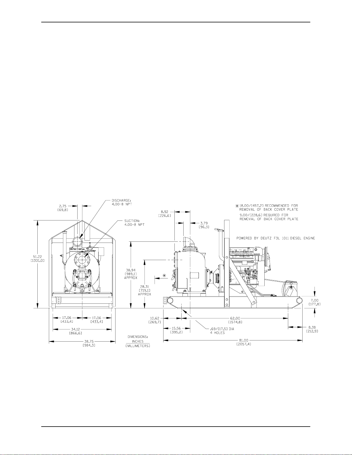
Clearance
It is recommended that 18 inches (457 mm) of
clearance be providedin front of the back coverto
permitremovalofthecoverandeasyaccess tothe
pump interior. A minimum clearance of 9inches
(229mm)must bemaintainedtopermit removalof
the cover.
SUCTION AND DISCHARGE PIPING
Pump performance is adversely effected by in-
creased suction lift, discharge elevation, and fric-
tion losses. See the performance curve and oper-
ating range shown on Page E-1 to be sure your
overall application allows pump to operate within
thesafeoperationrange.
Materials
Either pipe or hose maybe used for suction and
discharge lines; however, the materials must be
compatiblewiththeliquidbeingpumped.Ifhoseis
used in suction lines, it must be the rigid-wall, rein-
forced type toprevent collapse under suction. Us-
ing piping couplings in suction lines is not recom-
mended.
Line Configuration
Keep suction and discharge lines as straight as
possible to minimize friction losses. Make mini-
mum use of elbows and fittings, which substan-
tiallyincreasefrictionloss.Ifelbowsarenecessary,
use the long-radius type to minimize friction loss.
Connections to Pump
Before tightening a connecting flange, align it ex-
actly with the pump port. Never pulla pipe line into
place by tightening the flange bolts and/or cou-
plings.
Lines near the pump must be independently sup-
ported to avoid strain on the pump which could
cause excessive vibration, decreased bearing life,
and increased shaft and seal wear. If hose-type
linesareused,theyshouldhaveadequatesupport
to secure them when filled with liquid and under
pressure.
Gauges
Most pumps are drilled and tapped for installing
dischargepressureandvacuumsuctiongauges.If
these gauges are desired for pumps that are not
tapped, drill and tap the suction and discharge
lines not less than 18 inches (457,2 mm) from the
suction and discharge ports and install the lines.
Installation closer tothe pump may result in erratic
readings.
SUCTION LINES
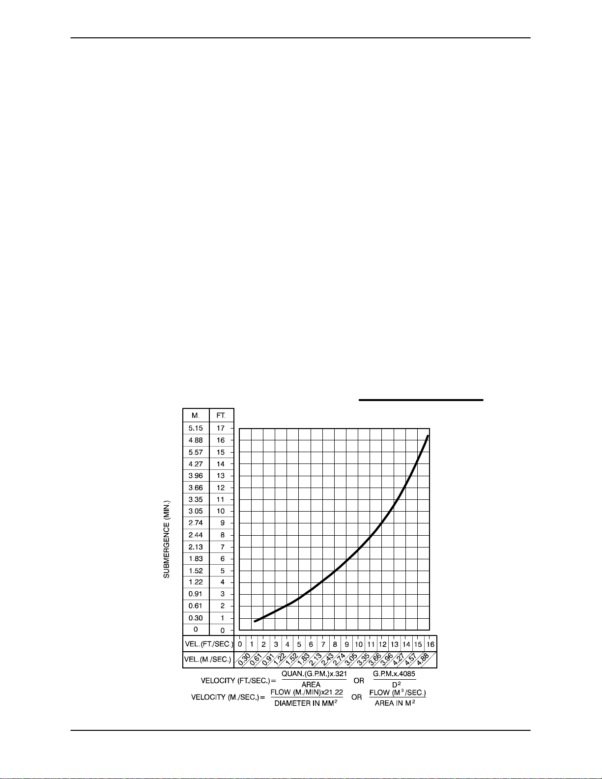
Toavoidairpocketswhichcouldaffectpumpprim-
ing, the suction line must be as short and direct as
possible.Whenoperationinvolvesasuctionlift,the
line must always slope upward to the pump from
the source of the liquid being pumped; if the line
slopes down to the pump at any point along the
suction run, air pockets will be created.
Fittings
Suction linesshouldbe the same size as the pump
inlet. If reducers are used in suction lines, they
should be the eccentric type, and should be in-
stalled withthe flatpart ofthe reducersuppermost
to avoid creating air pockets. Valves are not nor-
mally used in suction lines, but if a valve is used,
install it with the stem horizontal to avoid air pock-
ets.
Strainers
If a strainer is furnished with the pump, be certain
touseit;anysphericalsolidswhichpassthrougha
strainer furnished with the pump will also pass
through the pump itself.
If a strainer is not furnished with the pump, but is
installed by the pump user, make certain that the
total area of the openings in the strainer is at least
three or four times the cross section of the suction
line, and that the openings will not permit passage
of solids larger than the solids handling capability
of the pump.
This pump is designedto handleup to 3 inch (76,2
mm) diameter spherical solids.