FireFlex Systems Inc. ICAF System Manual

Operation &
Maintenance Manual
FM-0723-0-02 A

Integrated Compressed Air Foam System
with Electric Failsafe Release
Owner's Operation and Maintenance Manual
FM-0723-0-5B

OWNER'S OPERATION &MAINTENANCE MANUAL
ICAF
- Integrated Compressed Air Foam System
FM-0723-0-5B
FireFlex Systems Inc.
1935 Lionel-Bertrand Blvd
Boisbriand, QC (Canada) J7H 1N8
Tel: (450) 437-3473 Toll free: (866) 347-3353
Fax: (450) 437-1930

OWNER'S OPERATION &MAINTENANCE MANUAL
ICAF
- Integrated Compressed Air Foam System
FM-0723-0-5B
Table of contents
ICAF COMPRESSED AIR FOAM SYSTEM WITH ELECTRIC FAILSAFE RELEASE
AND
FIREFLEX
ARC-1 CONTROL PANEL
Description Form No
General Section..........................................................................................................................FM-0723-0-07
1. Applicable standards
2. Listings & Approvals
3. Environment
4. General description
5. Features
Configuration Description
Release systems
Installation
Preliminary inspection before placing the system in service
Placing the system in service
Mechanical trim section
1. System operation
Emergency Shut-off instructions
Post discharge instructions
Placing back the system in service after operation
Inspection, tests and maintenance
Controls Section........................................................................................................................FM-0723-0-26
User Interface
1. System status lamps
2. Keyboard – System main control keys
3. Keyboard – Menu navigation keys
4. Keyboard – User defined keys
5. Local alphanumeric display
System sequence of operation
System wiring details
Sequence of Operation..............................................................................................................FM-06IM-0-83
Automatic discharge
Manual discharge
Automatic discharge stop
Emergency discharge shut-of#f
Valve supervisory
System Wiring............................................................................................................................FM-06IM-0-84
System wiring details
Continued on next page…

OWNER'S OPERATION &MAINTENANCE MANUAL
ICAF
- Integrated Compressed Air Foam System
FM-0723-0-5B
Table of contents (cont'd)
ICAF System Trim Schematic ..................................................................................................FM-0723-0-10
1. Description
2. Normal condition
Trim schematic
Trim components
Air Supply Section.....................................................................................................................FM-0723-0-12
1. Design & selection
2. Interconnection piping to ICAF system
3. Operation
4. Recharge cylinders
5. Maintenance and Inspection
Foam Supply Section ................................................................................................................FM-0723-0-13
1. Foam storage tank
2. Foam concentrate
3. Foam tank design and selection
4. Interconnection piping to ICAF system
5. Operation
6. Filling procedure
7. Maintenance and Inspection
System Characteristics Section ..............................................................................................FM-0723-0-14
Mounting & installation details
Dimensional data
User Notes .................................................................................................................................FM-0723-0-16
Limited Warranty

OWNER'S OPERATION &MAINTENANCE MANUAL
ICAF
- Integrated Compressed Air Foam System
FM-0723-0-5B
Copyright © 2004-2009
FireFlex Systems Inc
.
All Rights Reserved
Reproduction or use, without express written permission from FireFlex Systems Inc, of any portion of this manual is prohibited.
While all reasonable efforts have been taken in the preparation of this manual to assure its accuracy, FireFlex Systems Inc
assumes no liability resulting from any errors or omissions in this manual, or from the use of the information contained herein.
ICAF ® is a registered trademark of FireFlex Systems Inc.
FireFlex Systems Inc. reserves the right to make changes to this manual and the data sheets herewith at any time, without prior
notification.

OWNER'S OPERATION &MAINTENANCE MANUAL
ICAF
- Integrated Compressed Air Foam System
FM-0723-0-5B

Page 1 of 6
I
CAF
-
Integrated Compressed Air Foam System
A
General Section
FM-0723-0-7H
General
1. Applicable Standards
Design and installation of CAF (Compressed Air Foam)
system is covered by chapter 7 of the NFPA 11. Complete
design and installation shall be prepared in full accordance
with F
IRE
F
LEX
's Design Manual (FM-090M-0-01).
Working plans shall be prepared only by persons fully
experienced and qualified in the design of fixed Compressed
Air Foam systems. Working plans shall be reviewed by
F
IRE
F
LEX
's engineering department prior to installation. No
deviation from these documents shall be made without prior
permission from F
IRE
F
LEX
Systems Inc.
Before the installation, the contractor installing the system
shall be familiar with the following documents and standards:
-NFPA 11, Standard for Low, Medium and High-Expansion
Foam
-NFPA 13, Standard for the Installation of Sprinkler
Systems;
-NFPA 72, National Fire Alarm Code;
-Applicable Local & State Building Codes;
-Any additional requirements of the Local Authority Having
Jurisdiction.
2. Listings and Approvals
In addition to being fabricated under strict ISO-9001
manufacturing and quality control procedures, your ICAF
system has also been tested and approved by Factory
Mutual Research <FM> under the heading: "Integrated
Compressed Air Foam Extinguishing System for Fixed Piping
Networks, "Class 5135" when installed with specific
components.
CAUTION ! Any unauthorized modification or addition made
on-site to a factory built Approved system will void this
Approval. Such modifications or additions may also void
the system's warranty as well. Consult F
IRE
F
LEX
Systems
Inc. Engineering Department before proceeding with any
such modifications or additions.
3. Environment
The ICAF system shall be installed in a dry and clean
location. Verify that all equipment is properly heated and
protected to prevent freezing and physical damage.
The system and its components must be kept free of foreign
matter, freezing conditions, corrosive atmospheres,
contaminated water supplies, and any condition that could
impair its operation or damage the components.
The frequency of the inspections and maintenance will vary
depending on these environmental conditions. The owner is
responsible for maintaining the fire protection system and
devices in proper operating condition.
4. General Description
CAF (Compressed Air Foam) is formed by combining air
under pressure, water and foam concentrate in the right
proportions, and then sending it through piping for distribution
on the protected area.
ICAF (Integrated Compressed Air Foam) system for fixed
piping networks consist of a complete system including the
compressed air supply equipment, the water control valve,
the foam tank and a mixing chamber, all pre-assembled, pre-
wired and factory tested. All electrical and mechanical
components of the system are contained in single or multiple
units and ready to be connected to a fixed piping network.
The CAF is carried using standard piping network as used for
conventional sprinkler or foam systems. To distribute the
CAF over the hazard area, nozzles specially developed for
CAF are used. These nozzles are offered in different types
for various applications. The nozzles are rotary type and
insure uniform CAF distribution over the protected area.
A detection network is used in parallel with the open type
nozzles. This network may be pneumatic or electric and may
be actuated by manual, fixed temperature, rate-of-rise
temperature, smoke or other means. When the detection
system operates, it gives an alarm and activates the ICAF
system. Because ICAF systems are often used in extra-
hazard occupancies, electrical and pneumatic detection
systems are by far the most common.
The connections required for installation are the water supply
inlet, the compressed air and the foam concentrate
interconnection with the system trim, CAF discharge outlet,
open type main drain, electrical connections with air cylinders
pressure transducer, water tank low level switches (when
applicable) and the electrical detection and alarm
connections. The discharge outlet is connected to a fixed
piping system of open nozzles.
The ICAF system is supervised in order to monitor its
integrity. The electrical detectors and associated wiring are
also supervised.
Note: Each ICAF system and mixing chamber is identified
with its unique serial number, which format is ARC00000
or NFS00000 and MIX00000. This number is located
inside the cabinet and on a sticker on the mixing chamber.
It is used as a reference to maintain records in our
computerized data base. Have these serial numbers
handy when calling for information on your unit.
5. Features
Your ICAF system is superior to many other products
available on the market now and has been manufactured by
the company that has introduced and developed the concept
of integrated fire protection systems on the market.
Main features are:
-Very efficient suppression capability using a minimal
amount of water
-Trouble free design for safe and easy application
-Available in different sizes and configurations to suit
hazards requirements

Page 2 of 6
A
ICAF
-
Integrated Compressed Air Foam System
General Section
FM-0723-0-7H
-Very dependable stainless steel pressure vessel type
foam tank, without bladder
-Air supply cylinders bank factory assembled and tested
-User-friendly standardized owner's manual with every unit
-Unique serial number on every mixing chamber
-Trim fully assembled and tested at the factory
-Grooved end water supply and drain connections on both
sides of the cabinet
-Sturdy 14 Gauge steel cabinet painted fire red with oven
baked polyester powder on phosphate base (powder
coated)
-Textured rust proof finish
-Neoprene gasket on all doors to eliminate vibrations
-Easily removable doors for ease of access
-Key-alike locks on all cabinet doors
-Manufactured under ISO-9001 quality control procedures.
Configuration Description
An ICAF system is a fixed deluge-type fire suppression
system which totally floods an area or hazard with
compressed air foam through a piping system of open
nozzles. The system piping is empty until the system is
activated by a pneumatic, electric or manual release system.
Single zone configuration can be used to protect smaller
hazards whereas multiple zones and multiple mixing
chambers configurations can be used to protect larger
hazards or a combination of smaller independent hazards.
System requires a reliable and automatic water supply. Air
supply is provided by compressed air cylinders mounted on a
skid and includes an air pressure regulator. Foam
concentrate is contained inside a stainless steel tank. Upon
system activation, the foam concentrate tank is pressurized
and water, air and foam concentrate are injected and mixed
together inside a mixing chamber. Compressed Air Foam is
then generated and moves inside the piping network toward
the distribution nozzles.
ICAF system trims including water, air and foam controls,
CAF mixing chamber and release system is factory
assembled in cabinets and available in self-contained,
remote controlled and extension unit configurations to suit
project's requirements. A description of the available units
follows:
អ
អអ
អSelf-Contained Unit: This unit includes all the
mechanical controls & trims, CAF mixing chamber(s) and
is provided with the release control panel.
Components size and quantity of mixing chambers are
determined by the system's flow and configuration
required to supply the nozzles in the hazard(s).
អ
អអ
អRemote Controlled Unit: This unit is used when an
additional zone is required to be protected by the same
system. This unit includes all the mechanical controls,
trims and CAF mixing chamber(s) and is provided with a
field wiring junction box in lieu of the releasing control
panel enclosure. This should then be connected to the
control panel of the self-contained unit.
Components size and quantity of mixing chambers are
determined by the system's flow and configuration
required to supply the nozzles in the hazards.
អ
អអ
អExtension Unit: This unit is used when additional mixing
chambers are required to supply a single zone with a
larger amount of nozzles. This unit includes the CAF
mixing chamber(s) without any controls or releasing
control panel. It should be used in parallel with a self-
contained unit or a remote controlled unit.
Water Supply
CAF technology offers an important reduction in the water
supply requirements compared to standard sprinklers or
foam systems. The system can operate with a water
pressure in the range of 50 to 175 psi (345 to 1206 kPa).
The ICAF system is dependable, automatic and capable of
providing the required flow and pressure for the required
duration.
ICAF system uses pneumatically actuated globe valves for
¾" (20 mm) diameter or Listed fire protection flow control
valves for 1½" (40 mm) diameters and up.
All the valves are rated up to a maximum of 175 psi WWP
(1206 kPa) and are available in the following diameters:
អ
អអ
អ
¾
" (20 mm)
អ
អអ
អ
1½" (40 mm)
អ
អអ
អ
2" (50 mm)
អ
អអ
អ
3" (80 mm)
When water pumps are required for system operation, they
shall be designed and installed in accordance with NFPA 20,
Standard for the Installation of Centrifugal Fire Pumps.
The water system shall be designed and installed in
accordance with NFPA 24, Standard for the Installation of
Private Fire Service Mains and their Appurtenances. A
strainer shall be provided on water supplies containing solids
likely to clog orifices. Such strainers shall be provided with a
cleanout port and shall be arranged to facilitate inspection,
maintenance and replacement.
For system including water tank, refer to WATER SUPPLY
SECTION H.
Air Supply
CAF is 90% compressed air. Air is provided by cylinders
bank as described in the AIR SUPPLY SECTION F .
The connection is used to supply compressed air between
the cylinders bank and the ICAF system. The piping is factory
prepared according to installation arrangement and is
supplied with the system. The system can be configured for:
អ
អអ
អSingle air interconnection line
4.
អ
អអ
អMultiple air interconnection lines
4.

Page 3 of 6
I
CAF
-
Integrated Compressed Air Foam System
A
General Section
FM-0723-0-7H
Foam Supply
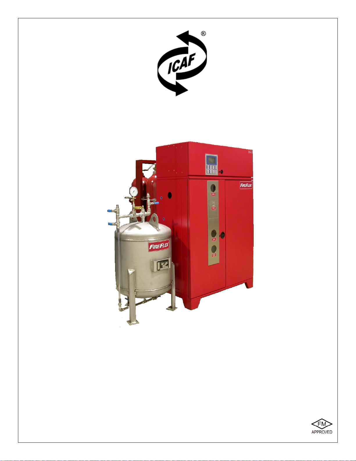
Foam concentrate is stored inside a stainless steel pressure
vessel type tank as described in the FOAM SUPPLY
SECTION G .
There are two interconnection lines provided on all foam
storage tanks. One connection is used to pressurize the
foam storage tank with compressed air
3
on alarm
condition, the other to provide foam concentrate to the mixing
chamber
2
. Piping between the foam storage tank and the
ICAF system is factory prepared according to the installation
arrangement and is supplied with the system.
System Supervision
Refer to MECHANICAL OPERATION SECTION E TRIM SCHEMATIC
and AIR SUPPLY SECTION F .
The release control panel supervises the air and water
supplies to insure system's reliability at all times.
A high pressure sensor (V7) is provided to supervise cylinder
bank pressure. The intent of this device is to provide a
supervisory signal if the cylinder bank pressure goes under
the minimum pressure required to provide air supply for the
specified discharge time. A cylinder bank pressure under
2200 psi (15,168 kPa) will cause the control panel to go into
supervisory condition.
An alarm pressure switch (B10) is provided with an alarm test
valve (B5). The alarm pressure switch is operated through
the system's water alarm line when the system is discharged.
System actuation, manual or automatic, will cause the control
panel to go into alarm and water flow conditions.
The main control valve (B1) is supervised from abnormal
position by an integrated supervisory switch. The
supervisory switch supervises the valve in an open position
and will cause the control panel to go into supervisory
condition in case the main control valve is not at fully open
position.
Release Systems
Refer to MECHANICAL OPERATION SECTION E TRIM SCHEMATIC.
The system can be activated manually, electrically using
solenoid valve or pneumatically using a pilot line. When
electrically activated, the release solenoid valve is controlled
by a release control panel listed for releasing and compatible
with the solenoid valve.
អ
អអ
អElectric Failsafe Release
Electrically controlled ICAF system is equipped with a
three-way solenoid valve (R2) controlled by the release
control panel, and requires external detection devices
(refer to INSTALLATION AND OPERATION MANUAL of the
release control panel for list of compatible devices).
In fire condition, when the detection condition is satisfied,
the release control panel energizes the three-way
solenoid valve (R2). The pneumatic control line is then
pressurized, causing the pneumatically activated control
valves for water (B7), air (A1) and foam (F1) to open
simultaneously, generating CAF through a piping system
into the discharge devices covering the protected area.
The CAF discharge is maintained if the AC power fails
and the battery backup expires while the system is
operating, and continue flowing until AC power is restored
or the system is manually shut-off.
អ
អអ
អElectric Release
Electrically controlled ICAF system is equipped with a
three-way solenoid valve (R2) controlled by the release
control panel and requires external detection devices
(refer to INSTALLATION AND OPERATION MANUAL of the
release control panel for list of compatible devices).
In fire condition, when the detection condition is satisfied,
the release control panel energizes the three-way
solenoid valve (R2). The pneumatic control line is then
pressurized, causing the pneumatically activated control
valves for water (B7), air (A1) and foam (F1) to open
simultaneously, generating CAF through a piping system
into the discharge devices covering the protected area.
អ
អអ
អPneumatic Release
Pneumatically controlled ICAF system requires a
pneumatic release system, equipped with fixed
temperature releases, and/or pilot heads.
Release trim, for pneumatically controlled ICAF system
utilizes a pneumatic actuator (R5) normally held closed by
pressure maintained in the pneumatic release system.
The air supply for the pneumatic release piping system
could be provided by the cylinders bank installed as part
of the ICAF system unit or by external air supply. It is
recommended to provide Inspectors Test Connections on
the release system.
In fire condition, the low pressure resulting from the
operation of the pneumatic pilot line release system
causes the pneumatic actuator (R5) to open. The
pneumatic control line is then pressurized, causing the
pneumatically activated control valves for water (B7),
air (A1) and foam (F1) to open simultaneously, generating
CAF through a piping system into the discharge devices
covering the protected area.
អ
អអ
អManual Release
For each release system type, in case of malfunction of
the release control panel or the release line, an
emergency release valve (R1) is provided for manual
override by the user.
Manual ICAF system actuation is accomplished by turning
the manual release valve (R1) to EMERGENCY RELEASE
position (as identified on the front of the unit).
In fire condition, once the manual release valve (R1) is in
EMERGENCY RELEASE position, the pneumatic control line
is then pressurized, causing the pneumatically activated
control valves for water (B7), air (A1) and foam (F1) to
open simultaneously, generating CAF through a piping
system into the discharge devices covering the protected
area.
The discharge continues after the manual release
valve (R1) is returned to its NORMAL position.

Page 4 of 6
A
ICAF
-
Integrated Compressed Air Foam System
Inspection and Maintenance Section
FM-0723-0-7H
Installation
ICAF system shall be located, installed, or suitably protected
so as to not be subjected to mechanical, chemical, or other
damage that could render them inoperative. Foam
concentrates are subject to freezing or deterioration from
prolonged storage at high temperatures, the system shall
therefore be located in a room with ambient temperature from
40
°
F to 110
°
F (4
°
C to 43
°
C).
Although it is preferable to locate the system outside the
protected area, in the case where there is no other
alternative, provisions should be made to ensure that the
system is not going to be exposed to fire or mechanical
damage in a manner that would affect its operation.
System shall also be installed so that inspection, testing,
recharging, and other maintenance are facilitated and
interruption to protection is held to a minimum.
1. Install the ICAF
S
ystem unit, cylinders bank and foam
concentrate tank according to the technical data
supplied.
Note: The drain collector shall be connected to an open
drain. Do not restrict or reduce drain piping.
2. Install the open nozzles piping network in accordance
with the ICAF System's Design Manual (FM-090M-0-01).
3. Install the releasing piping (if applicable), detection and
signaling circuits in accordance with applicable NFPA
standards.
4. Conform to local municipal or other codes regarding
installations of fire protection systems.
5. Perform preliminary inspection outlined below prior to
putting system in service.
6. Put the system into operation as outlined below.
7. Perform the annual inspection sequence and test each
detector and alarm unit.
8. If the system does not operate as it should, make the
necessary corrections according to manuals issued or
consult your distributor or F
IRE
F
LEX
Systems Inc.
9. Make sure that the building owner or a delegated
representative has received instructions regarding the
operation of the system.
Inspections, Tests & Maintenance
Regular inspections, tests, and maintenance should be
performed at intervals specified in this document to verify that
the ICAF system is in good operating condition and that it
functions as intended. Components shall be restored to full
operational condition following inspection and testing.
The frequency of the inspections may vary due to
contaminated water supplies, corrosive or humid
atmospheres as well as the condition of the air supply to the
system. In addition to the instructions herewith, local
Authority Having Jurisdiction may have additional
maintenance, testing and inspection requirements which
must be followed.
Warning ! Any system maintenance which involves placing
a control valve or detection system out of service may
eliminate the fire protection capabilities of that system.
Prior to proceeding, notify all Authorities Having
Jurisdiction. Consideration should be given to the
employment of a fire patrol in the affected areas.
RESPONSIBILITY of the Owner:
1. The responsibility for properly maintaining the
compressed air foam system shall be that of the owner
of the property.
2. Inspection, testing, and maintenance shall be
implemented in accordance with procedures meeting or
exceeding those established in this document.
3. These tasks shall be performed by F
IRE
F
LEX
's
authorized personnel who have developed competence
through training and experience.
4. It is the responsibility of the owner to promptly correct or
repair deficiencies, damaged parts, or impairments
found while performing the inspection, test, and
maintenance requirements of this document.
5. Corrections and repairs shall be performed by qualified
F
IRE
F
LEX
's authorized personnel.
6. The building owner shall not make changes in the
occupancy, the use or process, or the materials used or
stored in the building without evaluation of the fire
protection systems for their capability to protect the new
occupancy, use, or materials.
7. Where changes are identified, the owner shall promptly
take steps to evaluate the adequacy of the installed
system in order to protect the building or hazard in
question. Where the evaluation reveals a deficiency
causing a threat to life or property, the owner shall make
appropriate corrections.

Page 5 of 6
ICAF
-
Integrated Compressed Air Foam System
A
Inspection and Maintenance Section
FM-0723-0-7H
Records:
1. Records of inspections, tests, and maintenance of the
system and its components shall be maintained by the
owner and made available to the Authority Having
Jurisdiction upon request.
2. Records shall indicate the procedure performed (e.g.,
inspection, test, or maintenance), the organization that
performed the work, the results, and the date.
3. Original records shall be retained for the life of the
system.
4. Test results shall be compared with those of the original
acceptance test (if available) and with the most recent
test results.
The following requirements are based upon NFPA-25.
Monthly:
INSPECTION:
ICAF Discharge Nozzles:
ICAF discharge nozzles shall be inspected visually and
maintained to ensure that they are in place, continue to be
aimed or pointed in the direction intended in the system
design, and are free from external loading and corrosion.
Misaligned discharge nozzles shall be adjusted (aimed) by
visual means, and the discharge patterns shall be checked at
the next scheduled flow test.
Only ICAF discharge nozzles are approved and shall be used
with ICAF system. Inspection shall verify that unlisted
combinations of discharge nozzles have not been
substituted.
Control Valves:
The valve inspection shall verify that the valves are in the
following condition:
1. In the normal open or closed position
2. Properly sealed, locked, or supervised
3. Accessible
4. Provided with appropriate wrenches
5. Free from external leaks
Flow Control Valves:
Valve enclosure heating equipment for ICAF system subject
to freezing shall be inspected during cold weather for its
ability to maintain a minimum temperature of at least 4°C
(40°F).
The gauge on the supply side of the flow control valve shall
indicate that the normal supply water pressure is being
maintained.
The gauge monitoring the ICAF system air pressure shall be
inspected monthly to verify that it indicates that normal
pressure is being maintained.
The flow control valve shall be externally inspected to verify
the following:
1. The valve is free from physical damage.
2. All trim valves are in the appropriate open or closed
position.
3. The valve seat is not leaking.
4. Electrical components are in service.
Quarterly:
INSPECTION:
Drainage:
The area beneath and surrounding a ICAF system shall be
inspected to ensure that drainage facilities, such as trap
sumps and drainage trenches, are not blocked and retention
embankments or dikes are in good repair.
System Piping and Fittings:
System piping and fittings shall be inspected for the
following:
1. Mechanical damage (e.g., broken piping or cracked
fittings)
2. External conditions (e.g., missing or damaged paint or
coatings, rust, and corrosion)
3. Misalignment or trapped sections
4. Low point drains (automatic or manual)
5. Location and condition of rubber-gasketed fittings
Hangers and Supports:
Hangers and supports shall be inspected for the following
and repaired as necessary:
1. Condition (e.g., missing or damaged paint or coating,
rust, and corrosion)
2. Secure attachment to structural supports and piping
3. Damaged or missing hangers
TEST:
Water-Flow Alarm:
All water-flow alarms shall be tested in accordance with the
manufacturer’s instructions.
Semiannually:
TEST:
Supervisory Switches:
A distinctive signal shall indicate movement from the valve’s
normal position during either the first two revolutions of a
hand wheel or when the stem of the valve has moved one-
fifth of the distance from its normal position.
The signal shall not be restored at any valve position except
the normal position.

Page 6 of 6
A
ICAF
-
Integrated Compressed Air Foam System
Inspection and Maintenance Section
FM-0723-0-7H
Annually:
TEST:
Control Valve:
Each control valve shall be operated through its full range
and returned to its normal position.
Main Drain:
A main drain test shall be conducted to determine whether
there has been a change in the condition of the water supply
piping and control valves.
Operational Test:
Operational tests shall be conducted to ensure that the ICAF
system responds as designed, both automatically and
manually.
The test procedures shall simulate anticipated emergency
events so the response of the ICAF system can be
evaluated.
Protection shall be provided for any devices or equipment
subject to damage by system discharge during tests.
Where the nature of the protected property is such that CAF
cannot be discharged for test purposes, the trip test shall be
conducted in a manner that does not necessitate discharge
in the protected area.
Where the nature of the protected property is such that CAF
cannot be discharged unless protected equipment is shut
down (e.g., energized electrical equipment), a full flow
system test shall be conducted at the next scheduled
shutdown. In all cases, the test frequency shall not exceed
3 years.
Where discharge from the system discharge devices would
create a hazardous condition or conflict with local
requirements, an approved alternate method to achieve full
flow conditions shall be permitted.
Response Time:
Under test conditions, the automatic fire detection systems,
when exposed to a test source, shall operate within the
requirements of NFPA 72, National Fire Alarm Code, for the
type of detector provided and the response time shall be
recorded.
Discharge Time:
The time lapse between operation of detection systems and
water delivery time to the protected area shall be recorded
for open discharge devices.
Discharge Patterns:
The discharge patterns from all of the nozzles shall be
observed to ensure that patterns are not impeded by plugged
nozzles and to ensure that nozzles are correctly positioned
and that obstructions do not prevent discharge patterns from
covering surfaces to be protected.
Where obstructions occur, the piping and nozzles shall be
cleaned and the system retested.
Pressure Readings:
Pressure readings shall be recorded at the main control valve
and the CAF outlet.
Readings shall be compared to the design pressures to
ensure the original system design requirements are met.
Multiple Systems:
The maximum number of systems expected to operate in
case of fire shall be tested simultaneously to check the
adequacy of the water supply.
Manual Operation:
Manual actuation devices shall be tested.
Return to Service:
After the full flow test, the system shall be returned to service
in accordance with the instructions described in this manual.
Low points in the ICAF system shall be drained after each
operation.
Records indicating the date the ICAF system was last tripped
and the tripping time as well as the individual and
organization conducting the test shall be maintained at a
location or in a manner readily available for review by the
Authority Having Jurisdiction.
MAINTENANCE:
Strainers:
Priming line strainer (basket or screen) shall be removed,
cleaned and inspected.
Every 5 years:
TEST:
Gauges:
Gauges shall be tested every 5 years by comparison with a
calibrated gauge. Gauges not accurate to within 3 percent of
the full scale shall be recalibrated or replaced.
INSPECTION:
Flow Control Valve:
The interior of the flow control valve shall be inspected to
verify that all components operate properly. Internal
components shall be cleaned, repaired, or replaced as
necessary.

Page 1 of 6
ICAF -
Integrated Compressed Air Foam System B
Control Panel Section
FM-0723-0-26B
User Interface
F1
F2
F3
Audibles
Silence
Ground Fault System
Reset
Partial
Disable
AC Power Alarm
Supervisory
Trouble
Alpha-Numeric Display
System Status LEDs
and Operation Keys
Menu
Navigation Keys
Function
Keys
System LED
Indicators Alarm Silence
/ Activate
Release
Acknowledge
Discharge
EnterMenu / Exit
System
Shut-off
Inspection
Log
Shut-Off Key
Activated
Section visible
through
the door window
Left
Right
Up / Previous
Down / Next
Contrast Adjustment
FM-072C-0-275 A
Log
Activated
Discharge
Suspended
Not Used
1. Normal conditions
- The green lamp identified AC POWER is activated in
continuous manner.
- All other lamps are deactivated.
- The alpha-numeric display shows default screen SYSTEM
NORMAL.
2. System status lamps
Alarm, Trouble and Supervisory lamps will flash for their
respective events until acknowledged, at which point the
lamp will illuminate steadily. The local alphanumeric display
will provide additional details for every event (refer to screen
details in the text).
- AC POWER: A green lamp that illuminates steadily to
indicate the presence of AC power and flashes when
system is on battery power only.
- AUDIBLES SILENCE: A yellow lamp that illuminates steadily
when the ALARM SILENCE switch has been depressed after
an alarm. Lamp will begin flashing upon subsequent
alarm.
- GROUND FAULT: A yellow lamp that illuminates steadily
during a ground fault condition.
- PARTIAL DISABLE: A yellow lamp that illuminates steadily
when any input or output circuit is disabled by the user.
- RELEASE: A red lamp that illuminates steadily when
solenoid(s) is (are) activated and release occurs. This
lamp will flash when discharge is stopped (cycling type
systems only).
- DISCHARGE: A red lamp that illuminates steadily when
the actual water flow has occurred.
- ALARM: Red lamp that flashes when an alarm occurs
and becomes steady after event have been
acknowledged.
- SUPERVISORY: A yellow lamp that flashes upon
activation of a supervisory device (such as a tamper
switch and air pressure switch or sensor) and becomes
steady after event have been acknowledged.
- TROUBLE: A yellow lamp that flashes for any trouble
condition and becomes steady after event have been
acknowledged. System internal routines trouble will
activate the trouble signals continuously.
- OPTION LAMPS: The three (3) option lamps (adjacent to
F1, F2 & F3) are used for various special functions.
Contrast adjustment: A small potentiometer is provided
on the circuit board to adjust the LCD contrast level. This
potentiometer (shown above) can be accessed from the
bottom of the LCD module when the cabinet door is open
and adjusted with a small flat screwdriver.

Page 2 of 6
B
ICAF -
Integrated Compressed Air Foam System
Control Panel Section
FM-0723-0-26B
3. Keyboard - System main control keys
Panel is provided with a membrane type keyboard as shown
on the previous page. Local sounder will beep once every
time a valid control key is depressed. Sounder will beep
twice anytime an invalid entry is made or user is scrolling too
fast with the navigation keys. Various system main control
keys are described below:
ACKNOWLEDGE:Every new event must be
acknowledged. Depressing this key will acknowledge
alarms, supervisory and troubles while in their respective
events screen. The panel has alarm and trouble resound
with lamp flash on subsequent events with alphanumeric
annunciation. The flashing lamp turns steady and the local
sounder is silenced once all events have been
acknowledged.
As shown above, before any event is acknowledged, the
alphanumeric display shows the three letter code 'NAK' in
front of the event description. Once acknowledged by the
user, this code changes to 'ACK'.
By default, each event has to be acknowledged
independently. The user can define in the TECHNICAL SETUP -
PARAMETERS menu that holding the key for 2 seconds will
acknowledge all the current category of events at once.
When this feature is enabled, a second beep will confirm the
command has been executed and all events will display the
code 'ACK'.
ALARM SILENCE / ACTIVATE:When alarms are
sounding, pressing once on this key will turn off all
the audible devices connected to the silenceable notification
appliance circuits (but not the releasing circuits). The
AUDIBLES SILENCE lamp will illuminate.
When alarms are not sounding, pressing and holding the key
for 2 seconds will activate the alarm condition, the notification
appliance circuits and the system alarm relays but not the
releasing circuit(s). The ALARM ACTIVATE function of the key
is always available and both functions are latching, so will
require a SYSTEM RESET to clear.
SYSTEM RESET:The SYSTEM RESET key will only
operate while the system is either displaying a normal
operating screen for lamp test or once all events in the
system event screens have been acknowledged. Trying to
reset the system while any event is still not acknowledged
will silence the system buzzer momentarily, then make it
beep twice and finally continuously again. Once all events
are duly acknowledged, a full reset sequence should take
only a few seconds to complete.
Under normal conditions, pressing on the SYSTEM RESET
key make the local sounder beep once and will also
perform a LAMP TEST function.
Under alarm, supervisory or trouble conditions, once all
events have been acknowledged and cleared, pressing
once on this key resets the system and breaks power to
all initiating device circuits, 4-wire smoke power and
option boards. It will also clear any activated output
circuits. Should any alarm or trouble still exists after the
reset, they will automatically re-activate the panel
(subsequent alarm function).
4. Keyboard - Menu navigation keys
UP / PREVIOUS:Pressing on this key once will
scroll up the highlight to the PREVIOUS line on the
alphanumeric display or increase the value of a digit.
Pressing and holding the key will scroll fast up through
the values of a digit.
DOWN / NEXT:Pressing on this key once will scroll
down the highlight through the NEXT line on the
alphanumeric display or decrease the value of a digit.
Pressing and holding the key will scroll fast down through
the values of a digit.
LEFT ARROW:Pressing on this key once will scroll
the cursor (underscore) sideways to highlight the
PREVIOUS digit or field on the alphanumeric display.
RIGHT ARROW:Pressing on this key once will
scroll the cursor (underscore) sideways to
highlight the NEXT digit or field on the alphanumeric
display.
Every time a valid navigation key is depressed, the local
sounder will beep once. Holding the UP or DOWN key
depressed for 2 seconds will return the cursor (highlight
on the active item) directly up to the first or last item or
field of any list, depending on the key selected.
The UP or DOWN keys will also scroll up or down a full
page in a list of items, thus accelerating navigation when
used the same way.
Depressing the same key again when already at the
beginning or the end of a list will make the local sounder
beep twice to indicate an invalid entry. Any invalid entry
will also make the sounder beep twice.
ENTER:This key is used to make and confirm
choices in the various user menus. It is also used
to validate an entry or select an option.
While within the SYSTEM NORMAL or SYSTEM EVENT
screens, pressing and holding the ENTER key for
2 seconds will give access to specific system data
screens.
First screen displays the SENSORS LIST / TEMPERATURE as
shown below, where up to 6 sensors pressures can be
displayed. The cursor also highlights the screen name
being accessed in the first line as shown below:

Page 3 of 6
ICAF -
Integrated Compressed Air Foam System B
Control Panel Section
FM-0723-0-26B
System temperature is displayed in the lower part of this
screen. Trouble signal will be activated on high or low
temperature indications (levels are factory defined). This
value is used for system performance analysis and should
not be used as a thermometer.
While in this screen, pressing on the RIGHT or LEFT keys will
scroll to display the BATTERY INFO. / GROUND FAULT status
screen or the TIMER STATUS screen as shown below.
In the BATTERY INFO screen the upper portion of the screen
displays the actual battery voltage, current and size. A minus
sign in the Battery Current indication shows battery load
when the system is powered by the batteries:
- BATTERY SIZE is displaying the value entered initially at the
factory or by the user. Refer to MENUS – BASIC SETUP for
additional details. CHARGING MODE is also displayed in this
section as per the current status of batteries:
- TRICKLE indicates a fully loaded battery on low charge
mode.
- CHARGING indicates a low battery condition on high charge
mode and will also display a timer showing how long the
condition has been active.
- DISABLE is displayed whenever the charger is turned off.
This condition appears when system is in alarm state,
when a battery fault has occurred or when AC power is off.
- TEST indicates that the batteries are in the system's
automatic battery test mode (after a cold start or 30 days
after last test). This mode also displays a timer showing
how long the condition has been active. If a bad condition
of battery is detected, system will go on trouble condition.
The bottom section's GROUND FAULT STATUS indication is
for technician use and displays factory codes on Ground
Fault condition for troubleshooting purposes. Refer to
TROUBLESHOOTING section for additional details.
In the TIMER STATUS screen, all the set values of the
various timers are displayed as shown in the example
below (actual screen may differ depending on system
configuration):
Pressing on the MENU / EXIT key will exit the display
altogether and return to the default screen.
Note: Next time the user will access this display, system
will automatically return to the last screen it was
displaying before exiting, making a quick return to the
same data much easier.
MENU / EXIT:Pressing and holding this key for
2 seconds activates the user menu screen on the
alphanumeric display and when pressed once
within a menu item, is used to exit from this menu item.
To exit from the menu entirely, press and hold the key for
2 seconds. Typically, the display will automatically return
to its default mode if no key activity is detected for a
period of about 5 minutes.
Once modifications have been done in a menu section,
exiting the menu will save all the new data for the entire
section in the system's memory. Individual items don't
need to be saved individually.
5. Keyboard -
Function keys
These three keys are configured for
special functions adapted to the
ICAF system mode, but their
programming is not accessible to the user and is made at
the factory. The keys functions are only available to the
user when in the Normal Screen and while navigating
through the System Events Screen.
Note: The keys usage is also contextual – depending on
the menu or utility, they can be used to perform other
systems related functions.
F1 F2 F3

Page 4 of 6
B
ICAF -
Integrated Compressed Air Foam System
Control Panel Section
FM-0723-0-26B
INSPECTION LOG is used in conjunction with the
ARC-1 PC Interface software. It is used at the
factory for testing complex sequence of operations
with the help of a PC connected to the system, by setting up
a flag in the sequence of operation. Once the sequence of
operation is activated, the PC will display all the events that
occurred between the activation and the de-activation of this
flag, making complex sequences verification easier. The log
can also be printed for archiving.
Pressing on the key will illuminate the LOG ACTIVATED LED
adjacent to the switch.
Not used.
SYSTEM SHUT-OFF is a special function associated
with ICAF Extinguishing systems. Pressing on this
function key anytime during the discharge sequence
and then manually closing the water main supply control
valve will completely stop the flow of the foam agent. The
SHUT-OFF KEY ACTIVATED LED adjacent to the switch will be
illuminated while the function is active.
Typically, to activate any function press and hold the key for
2 seconds. Press and hold the key again to return to its
normal status. Key status will also be indicated on the alpha-
numeric display bottom section as described earlier.
6. Local alphanumeric display
The ARC-1®Analog Release Controller is provided with a
local alphanumeric display, model LAA, mounted on the front
door that provides detailed indications for status display,
operation and programming of the system. It is provided with
a soft membrane keyboard accessible by opening the front
key locked door. The alphanumeric display and the main
indicating lamps are visible through the door window at all
times.
Upon initial power up, the local sounder will be heard for
2 seconds then will automatically stop. At the same time, the
alphanumeric display will become momentarily blank and
then will show a scrolling SYSTEM RESET indication. It will
also momentarily display the P&P IN PROGRESS indication
while the system's plug and play routine is executed.
Note: The plug and play routine is automatically verifying
system integrity and module placement at both the initial
start-up and system reset.
The start-up procedure should last only a few seconds,
after which, if the system is back under normal condition,
the alphanumeric display will show the SYSTEM NORMAL
screen, similar to the one shown below:
Note: Should the start-up routine take more than
2 minutes and system seems to be hung, perform a
cold reset by removing power to the unit and back. If
problem continues, contact your nearest FIREFLEX
Authorized Distributor.
This screen displays the system configuration description
such as fixed discharge system in the example above
and the system status in a black window.
The black bottom line typically shows current date and
time on the left and right respectively. In the center, the
Function Keys status indicator code displays status of an
activated function for the corresponding key: A "1"
indicates a function is activated by Function Key F1, a "2"
for F2 and a "3" for F3. No change or a "0" indicates that
the function key(s) is (are) normal or not, assigned to any
special function. Refer to paragraph 5 for additional
details.
Depending on the specific menu screen, an alternate
bottom black line shows number of alarms, supervisory
and trouble events, followed by the current date and time
when an event is present.
Note: All the alphanumeric display screens shown
throughout this manual are typical and for general
information only. Actual screen details may vary
depending on selected configuration and conditions.
Time and date on initial start-up will show default values
and will have to be adjusted by the user (see MENUS –
ACCESS LEVEL 2 for detailed instructions). Furthermore,
time and date will return to the last event values in
memory every time the system power is completely
removed (both AC and battery stand-by).
Upon any event, the SYSTEM NORMAL screen will change
to the SYSTEM EVENT screen and show all current events
and their status.
Shown below is a flow chart describing in which order the
system keys must be operated in case of various events:
(only after all events
have been processed)
NEW EVENT ACKNOWLEDGE RESET
ACKNOWLEDGE
ALARM(S)
EVENTS:
ALARM
SUPERVISORY
TROUBLE
RESET
ACKNOWLEDGE
SUPERVISORY(S)
ACKNOWLEDGE
TROUBLE(S)
SINGLE EVENT OPERATION:
MULTI EVENTS OPERATION:
(only after all events
have been processed)
F1
F2
F3

Page 5 of 6
ICAF -
Integrated Compressed Air Foam System B
Control Panel Section
FM-0723-0-26B
Here is a simulated SYSTEM EVENT screen illustrating the
various displays:
The first line in the screen gives the number of events per
category in the following priority: Alarm, Supervisory and
Trouble. Scrolling through the three categories is done using
the following keys:
Pressing on the RIGHT ARROW key will move the
highlight to the next category of events at the right, ie:
from Alarm to Supervisory or from Supervisory to
Trouble. When doing so, events of the highlighted category
will be listed below.
Pressing on the LEFT ARROW key will move the
highlight to the previous category of events at the left,
i.e.: from Trouble to Supervisory or from Supervisory
to Alarm. When doing so, events of the highlighted category
will be listed below.
Note: The same function is applicable whenever the first line
of the display shows a few choices with one highlighted as
shown in the figure above.
Current events are displayed in the list, identified as 'NAK' for
Not Acknowledged, or 'ACK' for Acknowledged, the first
event remaining highlighted until acknowledged. Up to 99
events are displayed per screen – (for the full list of events,
use the EVENTS LOG). Note the cursor at the right side of the
screen. The position of the black square indicates how far in
the list the display has gone.
Next is the technical section, displaying various data for
the highlighted event:
TYPE is a three letter code displaying which type of event
is highlighted where:
ALM = Alarm
TBL = Trouble
SUP = Supervisory
NOP = Not Operated.
OCCUR displays the number of occurrences of the event,
which is particularly useful in case of intermittent
events to see how many times the event occurred.
Total number of occurrences displayed in the even log
is factory limited:
- Alarms: 5
- Supervisory: 4
- Troubles: 3
STATUS shows the actual status of the circuit where:
ACT = Active
NRM = Normal
ENABLE indicates if the circuit is enabled or disabled.
YES = Enabled
NO = DISABLED
CIR.ID displays a 5 digit code used by the factory,
describing module placement, circuit type, zone
number and type of activation. Refer to
TROUBLESHOOTING in Appendix D for additional details
on these codes.
DATE displays the date and time stamp at which the
highlighted event occurred.
Note: Alarms have priority and will always override any
other event. The alarm screen will always display first
and over any other screen that might be displayed at
the time of the alarm.
Inspection Log
The function key F1 labelled INSPECTION LOG is used in
conjunction with the ARC-1 Remote Interface software for
PC.
For additional information on the operation of the ARC-1
Controller, refer to the ARC-1 Installation & Operation
Manual FM-072Z-0-01.

Page 6 of 6
B
ICAF -
Integrated Compressed Air Foam System
Control Panel Section
FM-0723-0-26B
This page is left intentionally blank

Page 1 of 2
ICAF -
Integrated Compressed Air Foam System
Sequence of Operation
FM-06IM-0-83A
System Sequence of Operation
IMPORTANT NOTICE ! The detailed sequence of operation
described below is specifically written for your application.
Other system's operation may differ greatly depending on
the system's requirements and particulars of the projects.
Always refer to the Sequence of Operation provided with
your unit for precise information.
The heat detectors are wired on two zones for operation in
crossed zones mode.
The activation of EITHER detection zones will cause the
following:
On the Control Panel Annunciator:
- the zone in alarm will be displayed,
- the ALARM LED will flash,
- the local buzzer will sound.
System Output Activation:
- the ALARM signalling circuit will be activated,
- two ALARM contacts for the ALARM transmission to
the Main Fire Alarm Building panel will be activated.
The activation of BOTH detection zones (crossed zones)
will cause the following:
On the Control Panel Annunciator:
- the zones in alarm will be displayed,
- the ALARM LED will flash,
- the local buzzer will sound,
- the Release LED will illuminate,
- the Discharge LED will illuminate.
System Output Activation:
- the ALARM signalling circuit will be activated,
- the release circuit will be activated and the CAF
discharge will occur,
- two ALARM contacts for the ALARM transmission to
the Main Fire Alarm Building panel will be activated,
- the DISCHARGE contact will be activated for auxiliary
function.
The activation of electrical emergency manual release
station will cause the following:
On the Control Panel Annunciator:
- the zone in alarm (MANUAL PULL) will be displayed,
- the ALARM LED will flash,
- the local buzzer will sound,
- the Release LED will illuminate,
- the Discharge LED will illuminate.
System Output Activation:
- the ALARM signalling circuit will be activated,
- the release circuit will be activated and the CAF
discharge will occur,
- two ALARM contacts for the ALARM transmission to
the Main Fire Alarm Building panel will be activated,
- the DISCHARGE contact will be activated for auxiliary
function.
The activation of mechanical emergency manual station
inside the ICAF cabinet will cause the following:
On the Control Panel Annunciator:
- the zone in alarm (WATERFLOW) will be displayed,
- the ALARM LED will flash,
- the local buzzer will sound,
- the Discharge LED will illuminate.
System Output Activation:
- the CAF discharge will occur,
- the ALARM signalling circuit will be activated,
- two ALARM contacts for the ALARM transmission to
the Main Fire Alarm Building panel will be activated,
- the DISCHARGE contact will be activated for auxiliary
function.
Automatic Discharge Stop
Following an ‘Automatic Discharge’ or an electric manual
discharge, CAF will discharge for duration of ten (10)
minutes, measured by a ‘soak timer’. At the end of the ‘soak
timer’ period, CAF discharge will automatically stop. The
Release LED of the affected Releasing Panel will then start
to flash.
Valve Supervisory
Typically, all valves are supervised for abnormal position.
A valve in wrong position will cause the following:
At the Control Panel Annunciator:
- the zone in supervisory will be displayed,
- the SUPERVISORY LED will flash,
- the local buzzer will sound.
System Output Activation:
- the SUPERVISORY contact will be activated for auxiliary
function.
Table of contents
Other FireFlex Systems Inc. Fire Extinguisher manuals