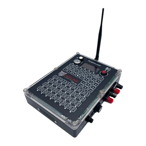
FIRELINX CM-64 User manual

WWW.FIRELINX.COM
USER MANUAL
(833) FIRELNX (347-3569)

Contents
CM-64...................................................................................................................................................................................... 1
CM-64 Panel Diagram ......................................................................................................................................................... 1
Power Button .................................................................................................................................................................. 1
Fire Button ...................................................................................................................................................................... 1
Charge LEDs..................................................................................................................................................................... 1
Control Buttons............................................................................................................................................................... 1
Navigation Buttons.......................................................................................................................................................... 2
Timing Controls ............................................................................................................................................................... 2
Numpad........................................................................................................................................................................... 2
Channel Selection............................................................................................................................................................ 2
Mini USB Port.................................................................................................................................................................. 2
USB Input ........................................................................................................................................................................ 2
2-Wire Ports .................................................................................................................................................................... 3
Power Input..................................................................................................................................................................... 3
SMPTE Input.................................................................................................................................................................... 3
OPD Input........................................................................................................................................................................ 3
Antenna Input ................................................................................................................................................................. 3
User Interface.................................................................................................................................................................. 3
Basic Setup .......................................................................................................................................................................... 4
Home Page .......................................................................................................................................................................... 7
Menu................................................................................................................................................................................... 7
[1] Caliber/Disables......................................................................................................................................................... 8
[2] RF Channel ................................................................................................................................................................. 8
[3] Join Process................................................................................................................................................................ 8
[4] File.............................................................................................................................................................................. 9
[5] SMPTE........................................................................................................................................................................ 9
[6] Edit............................................................................................................................................................................. 9
[7] Update ....................................................................................................................................................................... 9
[8] Reset ........................................................................................................................................................................ 10
[9] Stealth Mode ........................................................................................................................................................... 10
Continuity Test .................................................................................................................................................................. 10
Wireless Wizard ................................................................................................................................................................ 11
Module Status................................................................................................................................................................... 11
OPD (Operator Presence Device)...................................................................................................................................... 11
OPN (Open Pyro Network)................................................................................................................................................ 12
FM-24 .................................................................................................................................................................................... 13

Buttons and Ports ............................................................................................................................................................. 13
Power Button ................................................................................................................................................................ 13
Repeater Button............................................................................................................................................................ 13
Navigation Buttons........................................................................................................................................................ 13
Continuity Test.............................................................................................................................................................. 13
Firing Pins...................................................................................................................................................................... 13
Power Input................................................................................................................................................................... 14
Antenna Input ............................................................................................................................................................... 14
2-Wire ........................................................................................................................................................................... 14
Firing Module Basic Setup................................................................................................................................................. 14
Home Page ........................................................................................................................................................................ 15
Menu................................................................................................................................................................................. 16
Name............................................................................................................................................................................. 16
RF Channel .................................................................................................................................................................... 16
Join Mode...................................................................................................................................................................... 16
Repeater........................................................................................................................................................................ 16
Continuity...................................................................................................................................................................... 16
Troubleshooting and Maintenance................................................................................................................................... 17
Changing a wiring terminal block.................................................................................................................................. 17
Cleaning the FM ............................................................................................................................................................ 17
Batteries........................................................................................................................................................................ 17
Opening the Case .......................................................................................................................................................... 18
Appendix ............................................................................................................................................................................... 19
Glossary................................................................................................................................................................................. 19

1
www.Firelinx.com
CM-64
64 Channel Command Module
CM-64 Panel Diagram
Power Button
This turns the Command Module
(CM) on. Press and hold this
button to power on the CM. Hold
the button until the internal lights
come on (about 3 seconds). If the
CM does not power on, plug in
the charging cord into the
charging port (Please wait 1
minute for the power to be ready
once plugged in). To turn the
power off, simply press and
release the button.
Arm Key
This is a key slot. Insert the key
and turn it clockwise then press
the ARM/SAFE button. Turning
the key counterclockwise will
disarm the system. The key must
turn from SAFE to ARM, it cannot
be left in the ARM state. The key
cannot be removed when in the ARM
position.
Fire Button
In Manual Channel Fire mode, pressing the fire button will fire the next firing channel on the
selected module. The fire button can also be used to start the time code in an Internal clock
show. It is also used to enable the firing of a SMPTE show. See the details below on each show
type for details.
Charge LEDs
These LEDs indicate the power status of the CM. The red LED indicates that the battery charger
is plugged in and providing power. The green LED indicates that the battery is fully charged.
Control Buttons
These buttons are used to select which screen the CM will display. These are the Home, Menu,
Continuity, Wireless Wizard, Module Status, Show, and OPN Interface screens. It also has the
ARM/SAFE button, which is used with the Arm key to arm the system.
Figure 1

2
www.Firelinx.com
Navigation Buttons
These buttons are used to navigate menus on the CM.
Timing Controls
The pause button can be used for the control of the timing of internally timed shows. In future
releases they will be used to control the Audio Module.
Numpad (10-key number pad)
The Numpad is used to navigate menus, make menu selections, change which module is being
viewed, etc. When there is a # on the screen, enter a number to select that selection, or select
that module. While some numbers, like the module ID, show as “001” the leading zeros do not
need to be entered on the pad when entering a module ID.
Channel Selection
The channel selection buttons are used in the SHOW menu and when selecting a caliber or
disable function. When firing a manual show, these buttons will select which firing pin will fire
next. Note these buttons do not fire the channel, they select the channel. The FIRE button is
then pushed to actually fire the selection. Once fired, the selected channel will automatically
advance to the next available shot, so that it does not have to be selected before firing. When
firing a scripted show, these buttons will activate the caliber/disable functions if they are written
into the show file. If a continuity test has been performed, the LEDs under the shots will
illuminate to show channels with good continuity.
When in the Calibers/Disables page, these buttons can be used to enable or disable the disables.
The Calibers/Disable page can be reached via the SHOW screens or the MENU->1 function.
Mini USB Port
This function is currently not in use. Future functionality will be to allow a tablet device to view
and control the CM.
USB Input
The USB port is used to load
choreography or software
updates. Plug the flash drive
with the choreography or
updates into this port. Files
must be stored in the root
directory of the drive. Cannot
be used to connect to
anything other than a USB
memory stick or thumb drive.
Figure 2

3
www.Firelinx.com
2-Wire Ports
These terminals are used for 2-Wire communications between the CM and all the Firing Modules
(FM). The color of the terminals is not significant. The polarity of the two wires does not matter
when it is plugged into the next unit. The connections can be made in daisy-chain order (one
cable in, one cable out) or star order (one cable in, two cables out) or any combination in the
network. It does not matter which output terminals are used for input and output, however, we
recommend for ease of debugging that you use the single input terminal set on the FM (near the
top) for the input, and one or both of the terminal sets near the bottom as outputs. *Note only
one connection can be made per set of 2-Wire terminals.
Power Input
This port is used for charging the
CM.
Tech Specs of Port: 5.5mm OD
2.0 mm ID such as the
Switchcraft S760 center positive,
outer negative, 12 volts max 1
Amp.
SMPTE Input
For shows running on SMPTE, this
port is used to input SMPTE to the CM via RCA cable. SMPTE is then automatically distributed to
the other modules on the show network.
OPD Input
For shows where an Operator Presence Device (OPD) is required, this port is used to connect the
OPD to the CM.
Antenna Input
For shows that desire wireless communication, screw in the “N” style 3dB radio antenna here. We
recommend that the antenna always be installed as a backup communications device even if the
2-Wire communications are connected. For greater signal strength and range, we recommend
raising the height of the unit so that the antenna is at least 8 inches (200mm) off the ground.
User Interface
The Graphical User Interface (GUI) is at the top
of the FM and CM modules and is an OLED
display for better operation in different
environments. Different pages of the display
are used to control different functions. The
HOME, MENU, CT, WW, MOD, SHOW, and OPN
buttons take you directly to the associated
function page. Once on that page, other
functions and displays may be reached. In
Figure 4, the MENU screen is shown.
Figure 3
Figure 4

4
www.Firelinx.com
Note that the number icons have circles around
them. This represents a button on the 10-key
Number Pad (Numpad). Pressing a number on
the Numpad will bring up a small entry box. Fill
in the number desired and press Enter. The
CLEAR button will erase all numbers in the box.
Also notice that a line of dots appears at the
bottom of the screen. This indicates that
another screen is available by pressing the
DOWN (NO) arrow button. Figure 5 shows the
Continuity Test (CT) screen. Note that when FMs are connected all four sides of the screen have
dotted lines, indicating that other functional screens are available in all 4 scroll button
directions.
Basic Setup
1. Turn ON FMs, Name Them, and Place in Field. In most system setup scenarios, the Firing
Modules (FM) will first be turned on and the Name or Module ID set for the position where it
will be wired. Press and hold the Power Button until the lights come on. It is recommended
that the Radio Channel be checked and tested (if used in the show) and the module Joined to
the Command Module (CM) before sending it to the field (see further instructions below). It
is, however, perfectly acceptable to do all of this at show setup. If CrewSafe™ local
continuity testing will be used, the show file should be loaded into the CM and given time to
download to all the FMs before continuity testing is performed. Continuity testing must still
be turned on and off by the Command Module, but it can be shown on the screen of the FM
by pressing the CT button.
2. Turn on the CM System – On the CM, press
the power button and hold until the lights
show, then let go of the power button. Lights
will turn on, a logo splash screen will appear,
and the Home screen will appear.
3. Loading File – The top left of the screen will
display the name of the current show file
loaded next to a folder icon. If the top displays MANUAL with no folder icon, then no show file
has been loaded. Only Manual firing will be allowed. To load a show file, insert a USB drive
with the show file (.CSV format) in the root directory. Then go to MENU->FILE:(press #key 4
and Enter).
Figure 5
Figure 6

5
www.Firelinx.com
Once in the FILES PAGE, select the proper show
file. If there are more than 4 show files on the
drive, the top will display PAGE 1/2, 1/3 etc.,
and the UP and DOWN arrows can be used to
scroll between the show file pages. The CM
will display the current download progress and
the progress of the upload. When the FM
displays FILE with a folder icon, that FM has
received the full show information. The CM
will give a final notification when download
to all connected modules is complete.
The HOME screen will now show the number of
modules detected on the left, and the number
of modules in the choreography on the right.
It is allowed that the number of modules
detected may be larger or smaller than the
number in the choreography. It will be larger
if you have added some modules to act as
repeaters or some were wired for additional manual firing. It may be smaller if you have
intentionally elected to remove one from the setup.
4. Continuity Test – Select the CT button to go to the Continuity Test Page. Hit OK to turn
continuity test mode ON/OFF. Our proprietary CrewSafe™ continuity circuitry allows you to
go through your Firing modules to look for errors or to check for continuity while pinning. It
can also be checked at the Firing Module by pressing the CT button.
•= means that there is a loaded shot that is currently in the choreography on that pin. The
shot is identified, continuity is good, and the shot is ready.
•? means that there is a loaded shot that is currently NOT in the choreography on that pin.
It can still be fired manually.
•X means that there is no shot loaded but this channel is currently in the choreography.
This should be corrected, but the show will still run if it is left disconnected. See the
“ACCEPT ERRORS” command below.
•* means that there is more resistance than expected on the pin, there might not be
enough energy to reliably fire every shot on that line.
When you have completed the continuity testing, go to the main CT menu and hit OK to
disable continuity testing. Continuity testing will automatically be disabled when the system
is ARMED, however it is wasting battery power if left on when not needed.
5. Arming System - To arm the system, first turn the arm key to the arm position, then press
the ARM/SAFE button. The Firing Modules will blink Red/Yellow for a few seconds as the
capacitor bank is being charged. Once charged, there is no recharge time requirement. All
channels may be fired simultaneously. When charging is complete the system will
automatically transition to the SHOW page.
Figure 7
Figure 8

6
www.Firelinx.com
6. Fire Show – Select the SHOW button (if necessary) to navigate to the Show Page. Here you can
fire a manual or scripted show. There are three separate firing pages, as shown below. Use
the Left (Back) arrow and Right (Next) arrow keys to switch from one page to another. This
can be done while the show is running because all three screens can be firing at the same
time. Once the system is armed you can fire the show. Turning the key back to the SAFE
position is one of the fastest and easiest ways to SAFE the firing system.
•Manual Show – To fire a manual show, use the navigation buttons to land on the manual
firing page. To change the FM that is being selected, use the Numpad to select any FM to
fire or use the UP and DOWN arrow keys to go to the Next and Previous module in
numerical order. To change the shot that is being fired, use the Channel Selection buttons.
Use the FIRE button to fire the shot. On each press of the FIRE button, the system will
automatically advance to the
next shot and, when
appropriate, advance to the
next module.
•SMPTE Show – To fire a SMPTE
show, use the navigation
buttons to land on the SMPTE
firing page. Set the cue of the
show if necessary, cues will
advance automatically for each
button press. Once SMPTE has
been connected and is playing,
the SMPTE time should begin
to roll on the CM. If a valid
show file has been loaded,
pressing the FIRE button will
allow the show to fire. The
show will not fire unless the
FIRE button has been pressed.
It is recommended to have at
least 30 seconds of pre-roll
before the first cue to ensure that the SMPTE timecode has been captured by all FMs.
The SMPTE timecode can be tested pre-show in the MENU->SMPTE function page.
•Internal Clock Show – To fire a show with the internal clock, use the navigation buttons
to land on the INTRL firing page. Set the cue of the show if necessary, cues will advance
automatically for each button press. If a valid show file has been loaded, use the FIRE
button to begin the show. If the show has been running and you need to pause the show,
press the PAUSE [||] button. The FIRE button will restart the show where it was paused.
With a Internal Clock show, the show starts at time 00:00.0 at the time the FIRE button is
pressed. Note that to fire a SMPTE show and an INTERNAL show at the same time, they
must be defined in the choreography as different Cues or Scripts. A choreography file can
have any number of defined Cues, each may be one or more timed events in sequence. To
change the Cue, simply enter the cue number on the Numpad on the SMPTE or INTRL main
page.
Figure 7

7
www.Firelinx.com
Home Page
1. File Icon - This icon displays when there is a file loaded on the CM, with the file name next to
it. If there is no folder and MANUAL is displayed, there is no show file loaded. You can fire
manually at any time with or without a show loaded. If a file has been loaded and you wish to
return to Manual-only mode, see MENU-->FILE section below.
2. Link Quality Icon - This icon displays the worst connection to any connected FMs.
3. Battery Level Icon - This icon displays the current battery level of the CM.
4. Connected Module Status - This displays the number of FMs connected to the CM and how
many are defined in the choreography file for the show. The first number is how many FMs
are connected to the CM, the second number is how many FMs are defined to be in the show.
If there is no show file loaded, they will always be the same number.
5. Messages - This area will display the most recent messages that the CM received (i.e. the
names of active or offline FMs).
6. Software Version - This is a scroll down indicator. Pressing the down arrow will display the
current software version installed on the CM or FM.
Menu
To navigate to the desired function, press the icon number and Enter on the Numpad.
Figure 9
Figure 8

8
www.Firelinx.com
[1] Caliber/Disables
Calibers are Firelinx’s way of disabling a specific
set of shots from firing. When creating a show file,
a caliber can be assigned to the shot, which is
traditionally but not necessarily the size of the shell
being fired. If the show has calibers programmed,
this page can be used to view or enable/disable the
calibers. The available disables will be listed under
the CALIBER LIST. When the list displays ENA, those
shots can be fired. If the list displays DIS, those
shots will not be fired. *If the disables are required to be set as anything other than the caliber
of the round, the show file can be edited in any .csv editor (text or spreadsheet) to allow for any
disable groupings desired, with indicative names
such as “wind”, “rain” etc.
[2] RF Channel
If the RF environment is known the user can
manually set the RF channel by going to MENU->RF
CH:(2). Here the user can enter the RF channel (1-
14). The CM will automatically change the RF
channel of any currently connected FMs to the new
RF channel. FMs not connected at this time can
have their RF Channels set manually as well. You may select this function to see to which RF
channel the CM is set without making any changes. See the Wireless Wizard (WW) function to
have the system determine the best channel automatically.
[3] Join Process
The JOIN process is used to protect the system
from outside interference by encrypting all
communications. Every FM must be “Joined” with a
single CM in order to decrypt the messages. Once
an FM is Joined, even another Firelinx CM in the
same area cannot connect to that FM. When in the
JOIN MODE menu, the menu will display the CM’s ID
Number. On the FM, hit the MENU button. Scroll
down to JOIN MODE and hit ENTER. If the numbers on the CM and FM match up hit YES. If the FM
is showing a different number, another CM is on the same RF channel. Press NO, and another
CM ID will be displayed. Continue until the correct CM is identified. If this happens, you may
want to change the RF channel of your system. Note: The ID is only 256 unique numbers, so it is
possible although highly unlikely that two CMs with the same ID could be in the same area at
the same time. If this happens, you will be able to tell because the module will not appear to be
talking to your CM. Wait a short period and then go through the Join process again. Both CMs
would have to be nearby, have the same ID, and both in Join mode at the same time to be
mistaken. Even though the CM ID is only 3 digits, the encryption ID is unique. Once joined, no
other CM can communicate with your module.
Figure 10
Figure 11
Figure 12

9
www.Firelinx.com
[4] File
If a USB storage device is connected to the CM with .csv show files in the root directory, they will
be displayed here. Firelinx can accept Finale Generic .csv files, Firelinx LT .csv files, and the
Firelinx generic show file formats. (To get a sample of what the Firelinx generic show file looks
like go to www.firelinx.com) or refer to the Appendix. If there are more than 4 show files on the
USB press the up and down arrow keys to scroll between the pages. Use the Numpad to select
the file to download. If there are FMs connected to the CM during this process, the CM will
automatically upload the choreography file to each of the applicable FMs. To remove the show
file from the CM, either download a new show file or with no USB inserted go to the File menu.
When prompted to switch to a manual show press YES. *Note the maximum number of files that
the CM can display is 16 show files to prevent the need to endlessly scroll through the list. If
more than 16 files are on the USB drive, please delete some of them or move them to a
subdirectory with your laptop or PC.
[5] SMPTE
This menu is used to test or monitor the
incoming SMPTE timecode, as well as to adjust
the SMPTE frame speed. To change the Frames
Per Second (FPS) of the incoming SMPTE
stream, press the corresponding numbers on
the Numpad and press ENTER to change the
timing. If the clock icon is displayed next to the
time, the SMPTE is currently detected by the
module. If there is no clock icon, the SMPTE is
not currently running to the module but it will continue its count of time. The firing system will
continue to operate even if the SMPTE signal is temporarily corrupted or the wire is broken. If,
when monitoring the incoming SMPTE signal, the clock icon flickers on and off it usually
indicates that the SMPTE frame rate is incorrect. Try different frame rates until the SMPTE clock
icon is steady for at least 10 seconds. If none of them seem to be steady, choose the best one
and the system will adapt to it.
[6] Edit
This option is currently not in use. It will be used to create simple scripts from within the CM
without the need for a computer to make a show file.
[7] Update
If a USB storage device is connected to the CM with an update file in the root directory, this is
where the update can be installed. The screen will display whether it is a CM, FM or OPN update
and the version number. If both exist, FM updates will be performed first, then OPN updates,
followed by CM updates. Pressing YES will install the update to the CM. An FM or OPN card must
be connected and Joined to the CM to receive its update. All FMs will turn themselves OFF after
the update is complete. Once the update is complete, it will return to the MENU screen. Re-run
the Update function to install the CM update. To download updates, go to
www.firelinx.com/update, download the files and transfer them to a USB flash drive.
Figure 13

10
www.Firelinx.com
[8] Reset
This is used for multiple show environments like a theme park show. Once the show has been
completed, when this is pressed the show clock, systems, and shot list will completely reset.
The system is now ready to perform the same show again.
[9] Stealth Mode
This function is used to hide the FMs when the LEDs may be bright and distracting during a
show. This might occur, for example, in a stage environment where the module may be visible
to the audience. When enabled the LEDs will turn off until a change of state. When in stealth
mode, if changing from Safe to Armed or Armed to Safe the LEDs will reenable. For example, the
modules will be illuminated and colored when the system is being set up, wired, and continuity
testing is performed. As the house is opened, the modules may be armed and the transition to
Red status observed. Then the lights can be turned off and they will remain off until the system
is taken to SAFE mode, and they will turn Green again so that the crew can know they are safe.
Continuity Test
Select the CT button to go to the Continuity Test Page.
Hit OK to turn continuity test mode ON/OFF. You can go
through your Firing modules to look for errors or to
check for continuity while pinning. NFPA regulations
require that the field be cleared when continuity is run.
This regulation was accepted because in all previous firing systems it was dangerous to turn on
testing. Often only a single component failure is the difference between testing an E-match and
firing an E-match. CrewSafe™ is possible because Firelinx takes a “Nine Zeroes Safe” approach
to continuity testing. That means the probability of accidentally firing a shell is very low. Use
this feature only if the pyrotechnician in charge and the authority having jurisdiction concur that
it is safe.
•= means that there is a loaded shot that is currently
in the choreography on that pin.
•? means that there is a loaded shot that is currently
NOT in the choreography on that pin.
•X means that there is no shot loaded but it is
currently in the choreography on that pin.
•* means that there is more resistance than expected
on the pin, there might not be enough energy to
reliably fire every shot on that line.
When you have completed the continuity testing, go to the main CT menu and hit ok to disable
continuity testing. Pressing the up arrow will bring you to the continuity test menu. Here you can
turn the continuity test on and off as well as change the display mode to show all shots, or only
show errors. The Show Errors Only function is very helpful, especially in large shows, because it
only displays the modules with errors so you don’t have to scroll through all of them to check.
If everything was good when continuity testing was completed, it makes it a much simpler test
to recheck the field near firing time to see if a wire had been broken or come loose.
Figure 14
Figure 15

11
www.Firelinx.com
Wireless Wizard
If the RF space is unknown Firelinx can scan the
area and determine the best channel. After
pressing the WW button, the CM will be in the
Wireless Wizard menu. Pressing OK will start a
scan of the RF space and will select the best RF
channel for the area. After the area has been
scanned the CM will display the suggested RF
channel. If the suggested channel is acceptable,
pressing OK will change the RF channel of the
CM and all connected FMs. If any FMs are off or
not currently connected they will be unaffected by this. FMs can be manually changed to the
new channel at any time. Note that the RF environment can change dramatically between an
early morning show setup time, and at showtime. It is recommended that the Wireless Wizard
be checked again about an hour before show time to see if the recommended channel has
changed.
Module Status
This page is used to monitor the status of FMs before, during and after the show. The first page
of this menu shows how many modules are currently connected. Individual modules can be
selected by using the Numpad or the direction buttons.
The display will show the module name (1), if
the module is ok (2), if the CM is synchronized
with the module (3), if the module is armed (4),
if the module is firing/has fired (5), if the
module is connected (6) and the module’s
battery status (7). The current Link Quality
(LQ) is shown lower left (8). The link quality is
simply the percentage of RF messages that are
making it through to the module. It is quite
normal for the LQ to be anywhere from 80% to
100%. Scripted files such as SMPTE and INTERNAL firing will work even if LQ drops into the 50%
range. For manual firing, LQ should be as high as possible, we recommend that repeaters be
added and/or the modules are raised off the ground if the LQ is lower than 90%. If the
choreography file has been successfully loaded, the file icon (9) will be displayed lower right.
OPD (Operator Presence Device)
An Operator Presence Device (OPD) can be utilized in the Firelinx system. When an OPD is
plugged into the CM, the OPD will automatically be activated. In order to fire a show, the OPD
button must be pressed before the fire button is pressed and throughout the entire show. If the
OPD button is released, the show will pause until the OPD button is pressed again, and the fire
button is pressed again.
Figure 16
Figure 17

12
www.Firelinx.com
OPN (Open Pyro Network)
An OPN card can be purchased separately and installed onto any CM or FM expanding the
abilities of both modules! The CM can receive an ethernet or DMX module allowing the CM to
send and receive signals via DMX and ethernet. The FM can receive DMX, Ethernet, and 32 pin
expansion cards, allowing DMX and ethernet communication through the FM as well as the
ability for 32 additional firing pins to be added to the FM. The OPN-32 card has an industry
standard Centronics-36 D-style connector that comes out the front side of the module and
attaches to a standard 32 shot slat.

13
www.Firelinx.com
FM-24
24 Channel Firing Module
Buttons and Ports
Power Button
This turns the Firing Module (FM) on. Press
and hold this button to power on the FM.
Hold the button until the internal lights come
on (about 3 seconds). If the FM does not
power on, plug in the charging cord into the
charging port (Please wait 1 minute for the
power to be ready once plugged in). To turn
the power off, simply press and release the
button.
Repeater Button
This button enables the repeater function on
the FM. When firing manually, it is
recommended that one FM be enabled as a
repeater. This provides the maximum signal
strength and more robust timing of the firing
signals. If too many modules are designated
repeaters, however, the LQ of the system can
actually go down. Only the minimum
number of repeaters necessary to bridge the
gaps between positions should be used.
Navigation Buttons
These buttons are used to navigate menus on the FM.
Continuity Test
This button enables the continuity test viewer on the FM. The continuity test is still controlled by
the CM, but this button allows the continuity results for this module to be viewed on the module
screen.
Firing Pins
This is where e-matches/squibs can be inserted to fire. They are easily replaceable for cleaning,
replacement or upgrade.
Figure 18

14
www.Firelinx.com
Power Input
This port is used for charging the FM.
Tech Specs of Port: 5.5mm OD 2.0 mm ID
such as the Switchcraft S760 center positive,
outer negative, 12 volts max 1 Amp.
In an emergency (dead battery), a 12V power
supply or high current battery such as lead
acid can be connected to this port. It will
need to produce at least 2A of current
during the Arming process, so a standard wall-wart transformer will not be sufficient.
Antenna Input
For shows that require wireless communication, screw in the radio antenna here. We
recommend that the antenna always be installed as backup communications even if the 2-Wire
system is connected.
For greater signal strength, raise the height of the unit so that the antenna is at least 8 inches
off the ground.
2-Wire
These terminals are used for 2-Wire
communications between the CM and
FMs. FMs can be daisy-chained or
connected in a star formation. Standard
22-24Ga scab wire can be used and it
does not matter which conductor is
attached to which terminal. We recommend that in order to make it easy to check for mis-wired
connections, connect the incoming wire to the single terminal pair, and then connect one or two
outgoing wires to the other terminal pairs. Daisy Chain wiring would be one wire in and one wire
out, where Star configuration is one wire in and two wires out. Any combination of Daisy-chain
and Star is allowed.
Firing Module Basic Setup
1. Turn on the System - Press and hold the power button. Lights will turn on and the screen will
light up. A logo splash screen will appear and then the Home screen. The system is now
ready.
2. Joining CM – To join FMs to the CM, on the CM go to MENU->(3): JOIN. On the FM press the
MENU key, and use the up and down arrow keys to select JOIN MODE. Press Enter. If the
numbers displayed on the CM and FM match, press YES to join them together. If the numbers
do not match, then the FM is trying to join a different CM. Press the NO button, and the FM
will display the ID of the next CM in the area. Continue until your CM is listed. If no numbers
are displayed the CM and FM might not be on the same RF channel. The RF channel can be set
manully by selecting the RF Channel option in the MENU.The Wireless Wizard function in the
CM can only change the RF Channels of FMs already joined and communicating.
Figure 20
Figure 19

15
www.Firelinx.com
3. Wiring the FM – To wire an e-match to the FM, strip both wires from the e-match and insert
each into the spring terminals in the respective slot of the FM. The orientation of the wires
does not matter, but we recommend that the end of the wire be stripped back about one inch
(25mm) and given a U bend to provide better contact with spring terminals. The numbers
below the spring terminals correspond to the channel for that slot. If the continuity test has
been turned on at the CM, press the CT button to see the continuity test results on the FM
screen.
4. Continuity Test – Select the CT button to go to the Continuity Test Page. When the CM is in
Continuity Test mode and the test is activated the FM’s LEDs will change to either Blue,
Magenta or Yellow. If the backlight LEDs are Blue, there are no shots detected. If the backlight
LEDs are Magenta, the FM is detecting one or more shots loaded. If the backlight LEDs are
Yellow, the FM is detecting that the continuity test system has failed an internal safety test
and is not sending the test current through the firing pins. If this happens contact Firelinx
support through www.firelinx.com. The screen will also display the following icons to show
the status of each channel:
•= means that there is a loaded shot that is currently in the choreography on that pin.
•? means that there is a loaded shot that is currently NOT in the choreography on that
pin.
•X means that there is not a shot loaded but is currently in the choreography on that
pin.
•* means that there is more resistance than expected on the pin, there might not be
enough energy to reliably fire every shot on that line.
5. Armed – If the module’s backlight LEDs are RED the module is armed and ready to fire.
Home Page
1. The clock in the top left corner of the
screen is displayed when the FM is
currently connected and synchronized
to the CM.
2. The folder icon displays if there is a file
currently downloaded into the FM. If the
folder is dashed with an X there is no
file currently downloaded. The title of
the screen will read MANUAL instead of
FILE
3. This icon displays the current signal
noise in the area, a high bar will display in a low noise area. If the bar is low move the FM to
a different area with a higher bar.
4. This icon displays the current battery level of the FM.
5. This displays the Name ID of the FM. All FMs must have unique Name IDs.
6. This icon displays if the FM is firing a shot due to choreography. This icon will be preserved
on the screen until the next ARM cycle, so that the operator can check the “Has Fired” status
before, during, and after the show.
7. This displays any messages generated by the FM system, such as if the FM is currently
connected or disconnected.
Pressing the down arrow will display the current software version installed on the FM.
Figure 21

16
www.Firelinx.com
Menu
Press the Up and Down arrow keys to select one of the
MENU entries.
Name
This section changes the ID for the FM. Use the
arrow keys to navigate and change the ID of the FM.
Press ENTER to set the ID (An ID of 000 is not
allowed).
RF Channel
This section is used to change the RF channel of the FM. Use the up and down arrow keys to
change the RF channel and press ENTER to save the change. Note this will only change the RF
channel of this particular FM.
Join Mode
This is used for Joining the FM to the CM. When the
CMs ID displays on the FM press YES to connect
them together. If the FM displays a different ID, the
FM is trying to join a different CM.
Repeater
This determines if this module will double as a
repeater. The repeater modules will re-broadcast their messages to other modules. Repeaters
help modules that are not within the range of the CM receive a CM message. The more repeaters
there are in a network, the more messages there will be in the airwaves, so if manual firing is to
be used, check that only the minimum number of repeaters to cover the area are on. Note: If
using manual firing, it is recommended that ONE module be turned to Repeater status so
boost the signal strength in the field.
Continuity
Once continuity has been enabled from the CM, this screen can be used to determine the continuity
of the FM wiring.
•= means that there is a loaded shot that is currently in the choreography on that pin.
•? means that there is a loaded shot that is currently NOT in the choreography on that
pin.
•X means that there is not a shot loaded but is currently in the choreography on that
pin.
•* means that there is more resistance than expected on the pin, there might not be
enough energy to reliably fire every shot on that line.
Figure 22
Figure 23

17
www.Firelinx.com
Troubleshooting and Maintenance
Changing a wiring terminal block
If a continuity test channel returns OPEN (not wired) but the match and wiring looks good, the
next step is often to remove the E-match and put a short length of wire across the two terminals.
If it still reports OPEN, then there is a problem with the connector block.
The connector block can be removed by unscrewing the Phillips head screws on either side of
the block and pulling the connector block upwards.
You may replace that block with another (contact Firelinx.com for replacements and spares) or if
that block was recently changed or otherwise disconnected from the FM, it is likely that the two
small connectors between the wiring block and the FM printed circuit board did not get seated
properly.
To insert a connector block, replace the two screws and lower them into the slots in the case as
the block is lowered towards the internal pins on the PCB. Carefully check that the left and right
alignment of the pads and connector pins are correct and hold the connector block straight up
from the board (90 degrees) and then slowly seat the pins. If there is resistance, it’s probably
not aligned correctly. Tighten the screws. We advise that a continuity test be performed on the
block channels to ensure that it was seated correctly.
Cleaning the FM
The modules often will come back from the field with dirt and pyro fallout on them. Most can
be removed with a soft damp rag. We recommend a toothbrush for cleaning the tops of the
terminals and the narrow spacing between the terminals.
Batteries
The Lithium-Polymer (LiPo) internal batteries are 7.4V 5200mAH. They have built-in safety and
charging systems, so we recommend replacement every 5 years with an approved Firelinx
replacement battery. Use of another battery type voids the warrantee. The batteries should not
be stored in an environment over 60 degrees Celsius or 140 degrees Fahrenheit. While the
internal batteries should last 8-12 hours in normal use, a second battery pack can be installed.
Note that if a second battery is installed, there will not be room to also install an Open
Pyro Network (OPN) bus expansion card.
Table of contents
Other FIRELINX Control Unit manuals
