Firemiks 450-3-PP-F-ALU-FM User manual

Firemiks AB
P.O. Box 8155, 104 20 STOCKHOLM, Sweden
phone +46-8-551 196 10 - info@firemiks.com - www.firemiks.com
INSTRUCTION
MANUAL
FIREMIKS –PP
PISTON PUMP TYPE
WITH AUTOMATIC FLUSHING
FM approved
Original English version
Document: FiremiksInstructionManual-AutoFlushing-PP-FMapproved
Document number: SPFA-FM
Revision number: 4919
Page 2/43
Firemiks AB Instruction manual version: SPFA FM
P.O. Box 8155, 104 20 STOCKHOLM, Sweden
phone +46-8-551 196 10 - info@firemiks.com - www.firemiks.com
INSTRUCTION MANUAL | FIREMIKS® - PP
PISTON PUMP TYPE WITH AUTOMATIC FLUSHING
This instruction manual applies to following models:
Model
450-3-PP-F-ALU-FM
450-3-PP-F-BRZ-FM
450-3-PP-F-SS-FM
800-3-PP-F-ALU-FM
800-3-PP-F-BRZ-FM
800-3-PP-F-SS-FM
1200-3-PP-F-ALU-FM
1200-3-PP-F-BRZ-FM
1200-3-PP-F-SS-FM
1800-3-PP-F-ALU-FM
1800-3-PP-F-BRZ-FM
1800-3-PP-F-SS-FM
1800-3-PP-F-ALU-SS-FM
1800-3-PP-F-BRZ-SS-FM
1800-3-PP-F-SS-SS-FM
2400-3-PP-F-ALU-FM
2400-3-PP-F-BRZ-FM
2400-3-PP-F-SS-FM
3200-3-PP-F-ALU-FM
3200-3-PP-F-BRZ-FM
3200-3-PP-F-SS-FM
With fixed admixture and automatic flushing of concentrate pump when
the 3-way valve on the concentrate pump inlet is closed, and aluminum,
nickel-aluminum bronze and stainless-steel material for the water motor
body. Brass or stainless-steel pump head for 1800 size.
FM Approved for use with FM Approved concentrates and discharge
devices.
TABLE OF CONTENTS
1EC Declaration of conformity............................................................................. 3
2Read this first! ................................................................................................... 4
3General description ........................................................................................... 6
4Installation......................................................................................................... 9
5Check before first start..................................................................................... 25
6Operation......................................................................................................... 26
7Maintenance.................................................................................................... 30
8Troubleshooting............................................................................................... 35
9Spare parts...................................................................................................... 38
10 Tables and drawings ....................................................................................... 40
11 Material recycling guide................................................................................... 41
12 Overview and repetition of paragraphs essential for safety.............................. 42
Appendix 1 –Data sheet
Appendix 2 –Dimensional drawing
Appendix 3 –Orgalime S2012; General conditions for the supply of mechanical,
electrical and electronic products.

Page 3/43
Firemiks AB Instruction manual version: SPFA FM
P.O. Box 8155, 104 20 STOCKHOLM, Sweden
phone +46-8-551 196 10 - info@firemiks.com - www.firemiks.com
1 EC Declaration of conformity
According to European Directive 2006/42/EC
Manufacturer:
Firemiks AB
P.O. Box 8155
SE-104 20 STOCKHOLM, Sweden
Tel: +46-8-551 196 10
www.firemiks.com, [email protected]m
This instruction manual applies to following models:
Model
450-3-PP-F-ALU-FM
450-3-PP-F-BRZ-FM
450-3-PP-F-SS-FM
800-3-PP-F-ALU-FM
800-3-PP-F-BRZ-FM
800-3-PP-F-SS-FM
1200-3-PP-F-ALU-FM
1200-3-PP-F-BRZ-FM
1200-3-PP-F-SS-FM
1800-3-PP-F-ALU-FM
1800-3-PP-F-BRZ-FM
1800-3-PP-F-SS-FM
1800-3-PP-F-ALU-SS-FM
1800-3-PP-F-BRZ-SS-FM
1800-3-PP-F-SS-SS-FM
2400-3-PP-F-ALU-FM
2400-3-PP-F-BRZ-FM
2400-3-PP-F-SS-FM
3200-3-PP-F-ALU-FM
3200-3-PP-F-BRZ-FM
3200-3-PP-F-SS-FM
With fixed admixture and automatic flushing of concentrate pump when
the 3-way valve on the concentrate pump inlet is closed, and aluminum,
nickel-aluminum bronze and stainless-steel material for the water motor
body. Brass or stainless-steel pump head for 1800 size.
FM Approved for use with FM Approved concentrates and discharge
devices.
The manufacturer Firemiks AB declares that the above products conform to
European Directive 2006/42/EC and are designed according to the following
standards: SS-EN ISO 12100-1 and 12100-2.
The product is manufactured under a production control system, which
guarantees conformity between the manufactured product and technical data.
Installation, connection, maintenance and usage should take place in
accordance with the products instructions and design, which are described in the
manufacturer’s technical documentation as well as according to practice. In
accordance with the EC Declaration of conformity, the product must not be
modified without the manufacturer’s permission. If this occurs, this documented
EC Declaration ceases to apply and the products owner is considered to be the
manufacturer and must verify and draw up an addendum to the EC Declaration
and file technical data for the inspection authority.
2019-12-03
Firemiks AB
Mikael Aredal, Managing Director

Page 4/43
Firemiks AB Instruction manual version: SPFA FM
P.O. Box 8155, 104 20 STOCKHOLM, Sweden
phone +46-8-551 196 10 - info@firemiks.com - www.firemiks.com
2 Read this first!
2.1 Check at the reception of the goods that the delivery is complete
and without damages. Any discrepancies and damages should be
informed to the transport company and the supplier immediately.
2.2 For your own safety it is very important that you read all
information in this Instruction Manual before you install and use
this equipment, especially the comprehensive section 12 Overview
and repetition of procedures essential for safety. We want to point
out that the user is responsible that the safety instructions are
followed strictly. See also the WARNING SIGNS on the unit.
2.3 The FIREMIKS unit must be assembled and installed by qualified
staff, with the necessary mechanical and technical skills, following
the user and safety instructions given in this manual. As the user,
you are responsible that the safety and operating instructions of
any other systems, environment or container where the FIREMIKS
unit is installed are followed.
2.4 Inform yourself about the fire-fighting concentrate (additive)
producer's instructions about leakages and spillage. Observe
especially the directions about spillage on hands and eyes. Assure
yourself also that local and national regulations are followed
concerning environmental protections regarding waste leakage,
spillage and tests with the fire-fighting liquid.
2.5 The unit must only be used under the working conditions specified
in this instruction. Any deviation from that requires the producer's
permission.
2.6 The user is responsible to carry out the instructions according to
chapter 7 Maintenance.
2.7 The unit is designed to dose fire-fighting liquids (=concentrate) in
fire-fighting main water line. The FIREMIKS is designed to serve in
fire emergencies. It is not suitable for continuous use. For all other
applications, contact must be made with Firemiks AB for an
approval, if possible to give such.

Page 5/43
Firemiks AB Instruction manual version: SPFA FM
P.O. Box 8155, 104 20 STOCKHOLM, Sweden
phone +46-8-551 196 10 - info@firemiks.com - www.firemiks.com
2.8 The unit itself makes noise when operating. Be sure to wear ear
protection when you are continuously exposed to high noise levels.
Model size
Approx. Noise level dB (A) at max
flow
450
81
800
84
1200-2400
90
3200
93
Noise level will vary with the installation. On isolated rubbers it will be lower, if
there is resonance in rigid piping, it will be a lot higher.
2.9 The maximum operating pressure of the unit is 16bar. If there is a
failure of the unit or the surrounding installation, powerful water
jets may occur. Always wear eye protection!
2.10 If necessary information is missing in this Instruction Manual,
please contact your distributor or Firemiks AB. This is particularly
important if the user believes that there exist risks that are not
covered in this manual.
2.11 If the unit is transferred to a third party, this instruction manual
must follow the unit.
2.12 Warranty terms: For the warranty of 2 years to be valid, all
instructions in this manual must have been followed carefully. Full
warranty terms are stated in Appendix 3 - Orgalime S2012; General
conditions for the supply of mechanical, electrical and electronic
products, unless otherwise agreed in writing.
Page 6/43
Firemiks AB Instruction manual version: SPFA FM
P.O. Box 8155, 104 20 STOCKHOLM, Sweden
phone +46-8-551 196 10 - info@firemiks.com - www.firemiks.com
3 General description
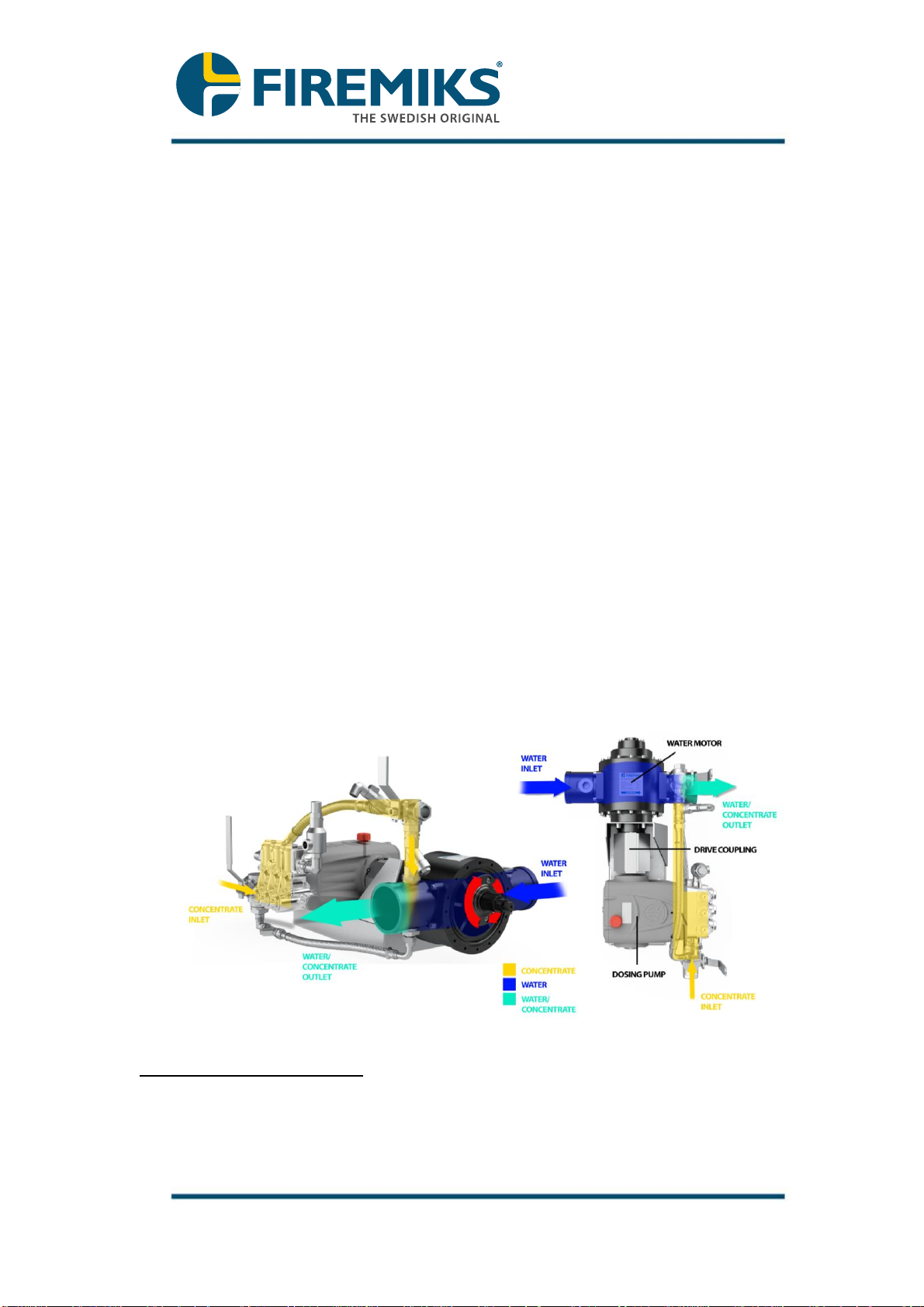
3.1 FIREMIKS® is designed with two displacement units direct coupled to
each other. FIREMIKS dosing system is driven solely by the existing
extinguishing water flow - no additional energy source is required.
The water flow from a main water pump goes through the FIREMIKS
water motor. The power of the water flow generates a circular rotor
motion, which is transferred to the concentrate pump. The concentrate
pump pumps concentrate into the water motor outlet creating the
water/concentrate mixture.
Since the water motor and the concentrate pump are directly connected
with the drive coupling, the system is by that flow-proportional. Dosing is
automatically adjusted from the amount of water that goes through the
FIREMIKS.
3.2 FIREMIKS is a dosing system which uses an atmospheric concentrate
tank and which requires positive pressure
1
of the concentrate liquid at
the pump inlet. Equipped as standard with a Manual air relief valve.
Flushing of the concentrate pump is done automatically when the
concentrate inlet is closed with 3-way ball valve.
The FIREMIKS is installed on the piping between the main
extinguishing water outlet and the discharge devices. Most often
the placement of the concentrate tank is decisive and the
FIREMIKS is installed in close vicinity of the tank.
Illustration of functioning principle
1
Positive pressure is reached when gravity feed overcomes the friction losses in the
piping between the tank and the Firemiks pump inlet at all operating conditions.

Page 7/43
Firemiks AB Instruction manual version: SPFA FM
P.O. Box 8155, 104 20 STOCKHOLM, Sweden
phone +46-8-551 196 10 - info@firemiks.com - www.firemiks.com
3.3 Overview main parts
3.4 Flow chart for foam liquids and other concentrates
Key properties of the FIREMIKS PP
In the following chapters the installation, use and maintenance of the
FIREMIKS will be discussed in detail. To quickly become familiar with the unit,
we list some of the key properties important for a trouble free use:
•The FIREMIKS is designed for use with a clean water supply only
•The FIREMIKS is designed to serve in fire emergencies, it is not
suitable for continuous use
•Before installing the FIREMIKS, all piping before must be flushed
thoroughly
Page 8/43
Firemiks AB Instruction manual version: SPFA FM
P.O. Box 8155, 104 20 STOCKHOLM, Sweden
phone +46-8-551 196 10 - info@firemiks.com - www.firemiks.com
•Do not expose the FIREMIKS to temperatures above 55 degrees
Celcius at any time
•Foam concentrate supply to the FIREMIKS pump inlet must have
positive pressure, gravity feed must at all times overcome the friction
losses in the piping between the tank and the Firemiks pump inlet.
•Place the FIREMIKS as close to the Foam concentrate tank as
practically possible.
•The FIREMIKS concentrate pump may not run dry
•The FIREMIKS must be operated/rotated, by water or by hand, at least
once a month to prevent the seals in the unit from seizing.
•For salt water use, do not allow salt water to dry inside the unit as salt
crystallization can stop the FIREMIKS from rotating.
The above is to give a general idea and is not binding. In case of doubt, always
refer to the chapters that follow.
3.5 Overview of flow performance
Unit
Min flow* (lpm)
at 1 cps
Min flow* (lpm)
1800 cps
(60rpm #4)
Max flow
(lpm)
continuous
450-3-PP-F-FM
112
155
450
800-3-PP-F-FM
135
169
800
1200-3-PP-F-FM
260
303
1200
1800-3-PP-F-FM
240
260
1800
2400-3-PP-F-FM
311
309
2400
3200-3-PP-F-FM
500
700
3200
*Min flow is here defined as the lowest flow at which correct dosing is reached at
system pressure 4bar. Minimum water flow rate varies depending on system
pressure and viscosity properties of the concentrate.
At flows below minimum flow, some dosing will still happen as long as the unit turns.
Once min flow is reached, correct dosing at higher flows is no longer sensitive to
fluctuations in pressure or viscosity for a given system
Page 9/43
Firemiks AB Instruction manual version: SPFA FM
P.O. Box 8155, 104 20 STOCKHOLM, Sweden
phone +46-8-551 196 10 - info@firemiks.com - www.firemiks.com
4 Installation
Please refer to the European standard EN 13565-2 for general requirements on
fixed foam systems for fire-fighting. Any Foam Fire Protection System must be
designed in accordance with the Authority Having Jurisdiction whether it is the
Insurance Carrier, Fire Marshal, end user or the relevant NFPA Fire Code(s.)

Page 10/43
Firemiks AB Instruction manual version: SPFA FM
P.O. Box 8155, 104 20 STOCKHOLM, Sweden
phone +46-8-551 196 10 - info@firemiks.com - www.firemiks.com
4.1 Storage
4.1.1 Respect the temperature limits as specified in the data sheet. Standard is 5 to
55 °C
4.1.2 If the unit/shipping package is stored in a contaminated environment where
there is a risk that dirt, dust, sand or other foreign particles can enter the unit
(flooding, sandstorm), make sure to provide additional protection to the
unit/shipping packaging or move it to a more secure place. Attempting to run
the unit with dirt lodged inside the water motor and/or pump may permanently
damage it.
4.1.3 Protection caps: let the yellow plastic protection caps and plugs remain on the
unit until it is installed unless you need to use the threads for installation.
4.2 Weight and lifting:
4.2.1 For weight see Appendix 1, Data sheet. Suitable points to lift the unit are
shown in Appendix 2, Dimensional Drawing. The 3200 unit also has holes for
lifting eyes shown on the Dimensional Drawing. The unit should not be
exposed to strokes or knocks.
WARNING! DO NOT lift the unit using the piping or hoses!
Page 11/43
Firemiks AB Instruction manual version: SPFA FM
P.O. Box 8155, 104 20 STOCKHOLM, Sweden
phone +46-8-551 196 10 - info@firemiks.com - www.firemiks.com
4.3 Requirements for the equipment before and after the FIREMIKS:
4.3.1 FIREMIKS is designed to operate with clean water. Water must be free
from sand, gravel and other debris that may wear out the volumetric water
motor quickly. In most cases the FIREMIKS can cope with occasional
instances of isolated foreign objects up to 2 mm size. If there is an acute risk
of particles entering the FIREMIKS or when polluted or contaminated water is
used, the piping system must be designed so that there is a suitable filter or
strainer where this pollution can be collected fully, placed before (upstream
of) the FIREMIKS. We refuse any responsibility for blockage or damage
of the water motor by any foreign objects in the water, whatever their
size. Please contact us if you need further guidance in this subject.
4.3.2 Note! Any new piping system before the FIREMIKS must be flushed out
thoroughly before the assembly of the FIREMIKS in the system. (There
are often foreign particles from the welding etc., left). Take care so other
foreign particles do not come into the unit during installation. Keep the
protection caps and plugs on the unit on as long as possible. Also take note
of the requirements on clean water for any discharge devices mounted
downstream of the FIREMIKS. NFPA 11 etc. also requires the foam delivery
system and main water supply system to be flushed before activating the
foam delivery system.
4.3.3 No minimum length of straight piping for the water supply before or after the
FIREMIKS is necessary for the functioning of the Firemiks but it may affect
pressure drop over the unit. If the pressure drop over the unit must remain
within specification there must be 5 pipe diameters straight pipe before and
after the unit.
4.3.4 Maximum flow in the system must be checked with a flow meter if water
source pumping capacity is higher than the max flow of the FIREMIKS. If
there is a risk that the water flow could exceed the stated max. flow, there
should be some kind of flow limiter placed before the unit. Exceeding
maximum flow of the unit may lead to incorrect dosing, damage and
failure of the unit.
4.3.5 General sizes and pressure loss over the unit
The details on the available main water connections to the FIREMIKS are in
the data sheet and on the dimension drawing, they are chosen for a
reasonable flow speed. The FIREMIKS unit itself has a pressure loss that is
mostly dependent on the water flow through the unit and to a lesser degree
on system pressure. At maximum system pressure of 16bar, the pressure
drop is roughly 0,2-0,3bar higher at full flow.
Unit
Water
connection size
Pressure loss (bar) at Max flow
and system pressure 8bar
450-3-PP-F-FM
DN50 –2”
2
800-3-PP-F-FM
DN65 –2 1/2”
2,3
1200-3-PP-F-FM
DN80 –3”
2,2
1800-3-PP-F-FM
DN100 –4”
2,6
2400-3-PP-F-FM
DN100 –4”
2,6
3200-3-PP-F-FM
DN125
1,9

Page 12/43
Firemiks AB Instruction manual version: SPFA FM
P.O. Box 8155, 104 20 STOCKHOLM, Sweden
phone +46-8-551 196 10 - info@firemiks.com - www.firemiks.com
4.3.6 Overspeeding at start-up. Even if the main water pump has a capacity equal
or below the max flow capacity of the FIREMIKS, over-speeding can happen
at the start if the main pipes are empty and the flow-limiting parts are located
after the unit. This risk for over-speeding could be minimized if the FIREMIKS
and the piping are completely filled with water up to the flow-limiting parts.
Gently filling the piping before the flow limiting parts, is also helpful to prevent
over-speeding of the FIREMIKS, i.e. not suddenly starting the main flow.
Units up to 2400 size have been tested without failure for 40% overflow
during 3 minutes. 3200 has been tested for 25% overflow during 5
minutes. Note that dosing at this time can be incorrect. Overflow is an
overload condition and will cause accelerated wear of the unit and must
be avoided.
4.3.7 Avoiding water hammer. If there is an alarm valve in the installation, the
FIREMIKS must be placed upstream from the alarm valve, to avoid water
hammer and a very sudden start of the unit.
4.3.8 Measuring unit rpm as a measure of flow and overspeed. It is possible to
measure the rpm of the FIREMIKS with a tachometer to get an indication of
the water flow through it and to make sure it does not overspeed. The unit
rpm is related to the main water flow through the unit and can be correlated to
the measured main water flow in steady state if available. At start-up of a dry
system, the peak rpm of the FIREMIKS thus gives a good indication of the
actual (over)flow through the FIREMIKS. As a rule of thumb, peak overspeed
rpm at start-up must not exceed the steady state rpm at max flow with more
than 40%.
Unit
RPM at max flow
450-3-PP-F-FM
1415
800-3-PP-F-FM
1054
1200-3-PP-F-FM
1265
1800-3-PP-F-FM
1255
2400-3-PP-F-FM
1210
3200-3-PP-F-FM
807

Page 13/43
Firemiks AB Instruction manual version: SPFA FM
P.O. Box 8155, 104 20 STOCKHOLM, Sweden
phone +46-8-551 196 10 - info@firemiks.com - www.firemiks.com
4.3.9 Note! It is extremely important that a shut-off valve is installed before
the FIREMIKS unit. This is to ensure a risk-free service/maintenance, i.e. the
risk for sudden rotation of the water motor due to unexpected water flow will
be eliminated by closing this valve. When working on the FIREMIKS, put a
clear sign on this valve stating: “Do not open, maintenance work in progress”.
4.3.10 In the case that the pressure capacity of the pumping system is higher than
the maximum rated pressure of the FIREMIKS unit, it is recommended that a
pressure-relief valve is installed in the main system.
4.3.11 Note! As in all safety-related installations, there should always be a
back-up plan. Never design the installation in such a way so that the water
flow through the FIREMIKS is the only source for fire-fighting water.
4.3.12 If the installation is to also operate with extinguishing water only by design (no
dosing), a by-pass should be installed and used around the FIREMIKS
system to avoid unnecessary wear of the unit. If the system has to run with
extinguishing water through the FIREMIKS (no dosing) by exception for a
short time (less than 10 min), be sure that the Selector valve Dosing/Flushing
(No. 4 on Flow chart) is in the Flushing position to avoid dry running of the
pump.
4.3.13 For wet pipe systems it is recommended to install a drain valve after the
FIREMIKS unit with a capacity of about 100 - 200 lpm to facilitate the rotation
of the water motor according to the maintenance instructions, see 7.3.4
4.3.14 It is possible, with only one main water pump, to design the piping system so
there is plain water from some outlets in the system and at the same time
additive admixed water from other outlets. The requirement is that the
minimum and maximum flow limits on the FIREMIKS are kept.
4.3.15 The outlet system after the FIREMIKS can be divided in many different ways,
also vary in heights, as long as the min. and max. flow limitations of the
FIREMIKS are kept.
4.3.16 Importance of positioning before dosing is reached. If the concentrate is
available at the pump inlet of the FIREMIKS, it only takes a few seconds of
rotation of the FIREMIKS unit before the concentrate is dosed into the water
at the outlet of the FIREMIKS unit. However, if the FIREMIKS is placed far
away from the discharge devices, it can take a long time before the mixture
had travelled through the piping and the foam is discharged. Without the need
of an external energy source other than the water flow to drive the FIREMIKS
unit, and if it is allowable and practical to have the concentrate tank remain
close to the FIREMIKS unit, it could be possible to move the FIREMIKS and
concentrate tank closer to the discharge devices to reduce this time before
foam discharge. If there are many discharge points, for this reason it could
also be more favorable to have several smaller decentralized FIREMIKS units
with their own concentrate supply instead of one centrally located larger unit.
Short response time can be critical to the outcome of a fire, and a good
system design using FIREMIKS could be the way to achieve this.

Page 14/43
Firemiks AB Instruction manual version: SPFA FM
P.O. Box 8155, 104 20 STOCKHOLM, Sweden
phone +46-8-551 196 10 - info@firemiks.com - www.firemiks.com
4.4 Concentrates:
4.4.1 The FIREMIKS can be used with all common foam liquids/fire-fighting
additives as long as they remain within the approved viscosity range (see
data sheet). As for example standard detergents, synthetic AFFF, AFFF-AR
and protein based FP, FFFP and FFFP-AR. Note: Minimum water flow rate
with correct dosing varies with viscosity properties of the concentrate and
system pressure. Higher viscosity and higher system pressure reduces
dosing performance, both resulting in an increased minimum flow. Should
there be any questions and thoughts about different additives, please contact
Firemiks AB and state additive type and brand. Usually it is possible to make
a factory acceptance test with the specific concentrate to be used, if the
concentrate is made available.
4.4.2 For concentrates with very high viscosities, we recommend the GP (Gear
Pump) type FIREMIKS. This type of pump does have a higher min flow. For
this pump type, performance improves with higher viscosity. At the time of this
writing, these are not FM Approved.
4.4.3 This FIREMIKS type is NOT suitable for Gel Forming additives. Contact your
distributor or Firemiks AB for a special version of the FIREMIKS that can
handle these additives.
4.5 Concentrate delivery to the unit
4.5.1 The supply of concentrate to the FIREMIKS unit must be done with
gravity feed. Gravity feed means that the lowest possible concentrate level in
the tank is higher than the inlet of the concentrate pump(s) on the FIREMIKS
in such a way that it delivers the required concentrate flow to the pump inlet
by gravity alone under all operating conditions. That is, without relying on
suction from the pump. Inlet pressure must always be at least equal or larger
than atmospheric pressure. Gravity feed thus always overcomes the friction
losses of the concentrate delivery piping/hoses to the FIREMIKS unit.
4.5.2 Gravity feed is a requirement; however, the concentrate pump usually can
suck up to half a meter below the inlet without problem. Nevertheless, this is
not to be relied upon and this suction scenario is not covered by warranty.
4.5.3 Maximum pump inlet pressure must be lower than system pressure at all
times (stationary and running) and at the most 3bar.
4.5.3.1 For dry systems without water pressure on stand-by, the highest tank level
should not be higher than 2m above the concentrate pump inlet, otherwise
the concentrate can leak into the system.
4.5.4 The concentrate is assumed to be stored in an atmospheric tank that supplies
the FIREMIKS.
4.5.5 Design of the gravity feed line
Always aim to have as short and easy flowing foam concentrate
feed to the FIREMIKS as possible as it is critical for reliable
performance of the FIREMIKS.

Page 15/43
Firemiks AB Instruction manual version: SPFA FM
P.O. Box 8155, 104 20 STOCKHOLM, Sweden
phone +46-8-551 196 10 - info@firemiks.com - www.firemiks.com
Place the concentrate tank and FIREMIKS as close together as is
practically possible.
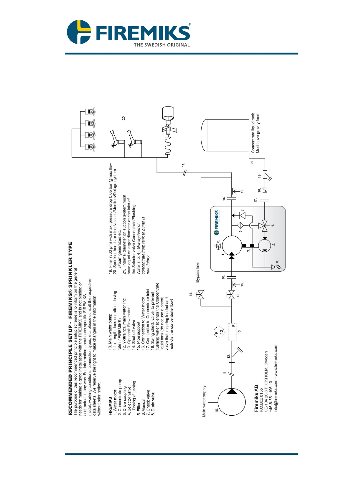
The concentrate feed line connects the concentrate tank with the
Selector valve Dosing/Flushing (No. 4 on Flow chart) on the
concentrate pump inlet.
The internal diameter on concentrate feed system must have equal
diameter as the inlet of the Selector valve Dosing / Flushing(No. 4 on
Flow chart), or one size larger if viscosity is on the higher end of the
allowed viscosity. (see also Appendix 2, Dimensional Drawing).
Avoid sharp 90-degree bends and keep the concentrate feed line as
free as possible from other flow restrictions (bends, bottom valves,
unnecessary filters).
Avoid elevation changes in the line where air bubbles may
stagnate and cause head losses and cavitation. Any other check
valves, ball valves, etc. should also have at least the same internal
diameter as the Selector valves.
Additional valves are discouraged as they increase the risk of operator
error and could cause dry running (see 4.9) if a valve is unintentionally
closed.
The concentrate feed line must be equipped with a free flowing filter of
300 μm or less; the filter must be positioned as close as possible to
the pump feed attachment. Even if the concentrate liquid to be used is
clean, the filter must be installed to prevent foreign bodies present in
the plant such as swarf, welding slag or scaling from entering the
pump.
It is advisable to put a transparent suction tube/hose just before the
inlet of the concentrate pump to make it easier to see when/if the
concentrate feed hose is completely filled with the concentrate. This
also minimizes the risk for tensions from a concentrate pipe to be
transferred to the concentrate pump.
It is very important that there are no air leakages in the concentrate
feed line anywhere between the tank and the concentrate pump. The
system should be pressure tested (preferably with a manual hand
pump up to about 2 Bar) before the start, to expose possible air
leakages, and designed in such a way that its seal is guaranteed to
last in time.
Page 16/43
Firemiks AB Instruction manual version: SPFA FM
P.O. Box 8155, 104 20 STOCKHOLM, Sweden
phone +46-8-551 196 10 - info@firemiks.com - www.firemiks.com
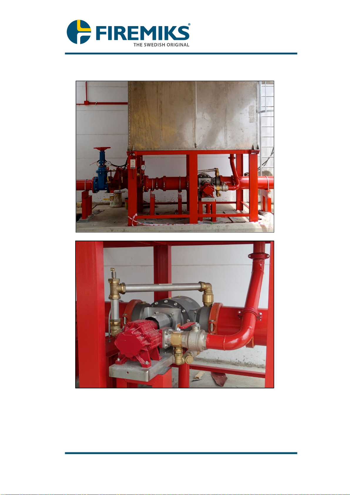
4.6 Unit installation:
Example of a good installation with gravity feed and short distance from
concentrate tank to a FIREMIKS (Gear Pump type shown).

Page 17/43
Firemiks AB Instruction manual version: SPFA FM
P.O. Box 8155, 104 20 STOCKHOLM, Sweden
phone +46-8-551 196 10 - info@firemiks.com - www.firemiks.com
4.6.1 The unit itself does not require any welding or painting for installation, suitable
pipe connections are to be bolted (cut groove) or threaded (BSP) and the unit
is held in place with screws, see 4.6.6. However, the supporting installation
can require welding and painting, in such case be careful not to contaminate
the in- and outlets of the FIREMIKS unit. It is not allowed to paint the
FIREMIKS unit.
4.6.2 The unit must be installed with the inlet and outlet of the water motor
and the pump shaft in horizontal positions (±5°). Other configurations of
the FIREMIKS are possible but must be configured and approved by Firemiks
AB.
4.6.3 The unit should preferably be installed and used in a frost-free environment. If
this is not possible it is important to drain the unit completely before frost
season. It should not be exposed to higher temperature than 55 degrees
Celcius even when the unit is not in use. This is both valid for the ambient
temperature and for the water temperature.
Note! Be observant for direct solar radiation that can heat up the
unit above 55 degrees Celcius, in these cases use a sun roof.
Contact us if higher temperature tolerances, above 55 degrees
Celcius, are needed.
4.6.4 If the unit has been contaminated during storage, see also 4.1, make sure to
carefully clean the inside of the unit before installation. If contamination is
especially aggravated and/or temperature limits have been exceeded, please
contact your distributor or Firemiks AB on how to proceed.
4.6.5 The water flow must be in the direction shown by the arrow on the upper side
of the water motor (Note! The direction of rotation of the drive shaft is
reversed compared with the direction of the water flow arrow). The unit can
optionally be configured with the water flow in the opposite direction. See also
Appendix 2, Dimensional Drawing.
4.6.6 There are two methods of mounting the unit.
4.6.6.1 Using the Mounting feet on pump bracket (pump flange on the 450-3-F-FM)
With these feet, the unit can easily be mounted on a flat surface using bolts
to secure the unit. See Appendix 2, Dimensional Drawing for the key
dimensions of the mounting interface.
IMPORTANT: it is very important that the main water lines before and after
connected to the water motor are well fixated, or flexible couplings are used
to connect to the Firemiks. Be sure there is no movement that can forcefully
distort the pump bracket of the Firemiks which can lead to failure of the drive
gear alignment and ultimately the whole unit. Do not rely on the FIREMIKS
bracket as a support for the main water line. If unsure, the second below
method is more secure.
The 450-3-F-FM has mounting holes on the pump flange, however the unit
is cannot be mounted on a flat surface without suitable support brackets
which depending on the installation can be provided by Firemiks AB.

Page 18/43
Firemiks AB Instruction manual version: SPFA FM
P.O. Box 8155, 104 20 STOCKHOLM, Sweden
phone +46-8-551 196 10 - info@firemiks.com - www.firemiks.com
4.6.6.2 Using the mounting plane under the water motor.
Using this method, the FIREMIKS complete unit must be held in place
ONLY by using the mounting plane with four threaded holes on the bottom
of the water motor. See Appendix 2, Dimensional Drawing for the key
dimensions of the mounting interface. It is advisable to have a support under
the concentrate pump bracket to balance the weight. NOTE! Do not use the
Mounting feet or in any other manner fixate the pump bracket, so to avoid
any movement in the drive gear alignment that can come from unequal
support between the fixture under the water motor and the pump bracket
support. Failure to follow this instruction can result in uneven rotation of the
concentrate pump or the water motor, and possible failure of the unit.

Page 19/43
Firemiks AB Instruction manual version: SPFA FM
P.O. Box 8155, 104 20 STOCKHOLM, Sweden
phone +46-8-551 196 10 - info@firemiks.com - www.firemiks.com
4.6.6.3 For alternative ways of fixating the unit, contact Firemiks AB.
4.6.7 Once the unit is installed horizontally, remove the plastic plug from the top of
the concentrate pump, and replace it with the supplied oil dipstick. The oil
dipstick is a secondary way to check the oil level and is also vented to remove
any pressure from the crank case during operation.
4.6.8 Be aware that the valves on the Firemiks are made of stainless-steel. If
assembling other stainless-steel threaded parts to the threads of the valves,
be sure to use suitable lubrication to avoid galling and the threads seizing
together permanently.
4.6.9 It is very important that there are no movements on the water main line that
could create tensions between the water motor inlet and outlet. If any such
movement exists on the connecting pipes, separate support(s) must be made
to stabilize the connection pipes before connecting to the FIREMIKS.
Alternatively, a flexible hose connection to the FIREMIKS is also a possibility.
4.6.10 Make sure there is enough space around the unit to enable easy access for
service and maintenance, especially on the back gable side of the water
motor (opposite side of the concentrate pump).

Page 20/43
Firemiks AB Instruction manual version: SPFA FM
P.O. Box 8155, 104 20 STOCKHOLM, Sweden
phone +46-8-551 196 10 - info@firemiks.com - www.firemiks.com
4.7 Valve maneuvering on the FIREMIKS unit
For the operating instruction of when the valves must be operated, refer to
section 6.1. This section considers the function of the valves.
Modification to valves will void warranty if this modification caused the incorrect
functioning or operation of the valves. Remove handles at your own risk, as this
makes it possible to incorrectly operate the valves and also makes it possible
to put back the handles in an incorrect orientation.
4.7.1 Manual selector valve Dosing / Flushing
The unit comes equipped with a manual selector valve for Dosing or
Flushing.
Warning: Always make a fast and determined switch with the
selector valve (No. 4 on Flow chart), leaving it only at its end
positions.
Otherwise, if the selector valve is left between its two end positions,
the valve may be open for both flushing and dosing and thus
pressurized flushing water can enter the suction line and pollute or
even overflow the concentrate tank.
Flushing Dosing
4.7.1.1 Supervisory switch
As per FM Approval standard, the unit comes equipped with a supervisory
switch 1NC+1NO that supervises the Dosing setting of the selector valve
Dosing / Flushing. This allows remote checking that the valve is in the
correct position.
Make: Bernstein TI2-U1Z W
Connection 4 screw connections (M3,5), cable entrance 1 x M16 x 1,5
Rated insulation voltage: Ui 250 V AC
This manual suits for next models
20
Table of contents
Popular Water Pump manuals by other brands

Ragazzini
Ragazzini RC2-Mxl Instructions for use

Interpump
Interpump Pratissoli KT-WK Series Repair manual

Dover
Dover Wilden Advanced Metal P200 Series manual

Waters
Waters 515 HPLC Operator's guide

Affetti Pumps
Affetti Pumps CGV-L user manual

GORMAN-RUPP PUMPS
GORMAN-RUPP PUMPS 10 Series Installation, operation and maintenance manual


