Firenzo Coaster User manual

Please read this booklet, for the safe installation of your
MULTI FUEL FIRE
The Appliance and Flue System must be installed in accordance
with AS/NZS2 18. Consult with the building authority having
jurisdiction to determine the need for a permit prior to commencing
the installation. Failure to follow these instructions may also void
your fire insurance and warranty.
INDEX
Item
1 Warnings
2 Installation Responsibilities
3 Floor Protector Requirements & Clearances
4 Assembly Instructions
5 Flue Requirements
6 Flue Installation Instructions
7 Water Heating

2
1. WARNINGS
1. WARNINGS1. WARNINGS
1. WARNINGS
THIS APPLIANCE SHOULD BE MAINTAINED AND OPERATED AT ALL
TIMES IN ACCORDANCE WITH THESE INSTRUCTIONS.
The Coaster is tested to AS/NZS 2 18:2001.
If this heater is incorrectly installed a house fire may result. For your safety follow
the installation instructions carefully.
Do NOT connect the heater to a chimney serving another appliance.
Although the exterior of the heater may appear cool, contact with the unit may cause
burns, warn children and others of the possibility of injury should they touch the
heater.
Do NOT dry clothing or unseasoned wood directly in contact with the heater.
Keep all household combustible materials at least 600mm away from front of the
heater. This includes clothing, furniture, wood, newspaper, plastic, matches, etc.
DO NOT USE FLAMMABLE LIQUIDS OR AEROSOLS IN THE VICINITY OF
THIS APPLIANCE WHEN IT IS OPERATING.
Use caution when reloading with fuel. Do NOT attempt to load fuel into the heater
when the fire inside the stove is at or near its peak.
Do NOT burn large quantities of paper or combustible material that would create an
extremely hot/quick fire.
USE ONLY DRY WOOD. AVOID BURNING WET OR GREEN WOOD.
THE USE OF SOME TYPES OF PRESERVATIVE TREATED WOOD AS A FUEL
CAN BE HAZARDOUS.
TIMBER TREATED WITH COPPER CHROMIUM AND ARSENIC TYPE
PRESERVATIVES WILL LEAVE TOXIC RESIDUES IN THE ASH, FIREBOX
OR WITHIN THE FLUE; TIMBER OFFCUTS FROM BUILDING
CONSTRUCTION WILL OFTEN CONTAIN BORIC SALTS. THE
COMBUSTION OF THIS MATERIAL OVER PROLONGED PERIODS CAN
PRODUCE ADVERSE EFFECTS ON REFACTORY LINING IN SOLID FUEL
APPLIANCES. EMISSION OF POISONOUS GASES CAN ALSO BE
EXPERIENCED WITH THE BURNING OF TREATED WOOD.
Driftwood with salt content will also cause rapid deterioration of the heater and
should not be used.
Edited 07/02/2011

3
2. INSTALLATION RESPONSIBILITIES
2. INSTALLATION RESPONSIBILITIES2. INSTALLATION RESPONSIBILITIES
2. INSTALLATION RESPONSIBILITIES
WARNING: THE APPLIANCE AND FLUE SYSTEM SHALL BE INSTALLED IN
ACCORDANCE WITH AS/NZ 2 18:2001 AND THE APPROPRIATE
REQUIREMENTS OF THE RELEVANT BUILDING CODE OR CODES.
ANY MODIFICATION OF THE APPLIANCE THAT HAS NOT BEEN
APPROVED IN WRITING BY THE TESTING AUTHORITY IS CONSIDERED
TO BE IN BREACH OF THE APPROVAL GRANTED FOR COMPLIANCE
WITH AS/NZS 2 18:2001.
CAUTION: MIXING OF APPLIANCE OR FLUE-SYSTEM COMPONENTS
FROM DIFFERENT SOURCES OR MODIFYING THE DIMENSIONAL
SPECIFICATION OF COMPONENTS MAY RESULT IN HAZARDOUS
CONDITIONS. WHERE SUCH ACTION IS CONSIDERED, THE
MANUFACTURER SHOULD BE CONSULTED IN THE FIRST INSTANCE.
Strict adherence to these instructions will meet these standards.
Any variation from these installation instructions or any doubt about them must be
checked against the requirements of the Standards.
WARNING:
Care must be taken to protect the wetback coil and associated pipe work if being
installed in a hard/corrosive water area. Damage caused to the Wetback coil if fitted
in a hard/corrosive water area will not be covered under the manufacturer’s warranty.
Please leave this manual with the owner when installation is complete.
Please complete for your records:
Coaster Serial Number:_______________________
Purchased from:_______________________________
Date of purchase:______________________________

4
3. FLOOR PROTECTOR REQUIREMENTS
3. FLOOR PROTECTOR REQUIREMENTS3. FLOOR PROTECTOR REQUIREMENTS
3. FLOOR PROTECTOR REQUIREMENTS
AND CLEARANCES
AND CLEARANCESAND CLEARANCES
AND CLEARANCES
If the heater is to be placed on or within 500mm of a heat sensitive floor, a floor
protector will be required. This shall consist of a continuous layer of heat resistant
material extending under the appliance to the perimeter of the protector. All joints
shall be fixed to prevent separation and shall be sealed to prevent any spilt ash or
embers contacting any heat sensitive material. Overall protector size shall be as per
diagram.
The heater and floor protector must be fixed to the floor for seismic restraint. Anchor
points are provided in the feet of the unit.
COASTER MULTI FUEL - (All clearances are with flue pipe shield
& Grill on rear cast top)
A B C D E F G H J K L M N O
100 275 300 110 100 230 595 420 860 905 1270 1095 675 600
Clearances are to a heat sensitive material

5
4. ASSEMBLY INSTRUCTIONS
4. ASSEMBLY INSTRUCTIONS4. ASSEMBLY INSTRUCTIONS
4. ASSEMBLY INSTRUCTIONS
1. Remove all packaging and timber.
2. Remove loose parts from inside the firebox.
3. Position the base with angle steel down onto the floor protector, taking the
necessary final clearance into consideration. The base has the flue centre indicated on
the flat steel bracket. The label next to this point states the minimum clearances from
the base to combustible surfaces. These measurements coincide with the figures on
page 4 for the heater clearances when assembled.
4. At this point a hole in the ceiling to accommodate the flue may be cut and the
liners installed.
5. Remove both front and rear top castings.
6. Place firebox on base. Secure with brackets provided.
7. Fit the wetback in accordance with accepted plumbing practice - please refer to
page 8. Ensure wetback is NOT pushed down; if it touches or comes in contact with
the baffle bricks this will cause wear which will void your warranty.
If NO wetback is to be fitted please ensure that blanking plugs are attached to the two
holes in the rear of the upper chamber.
8. Replace the rear top casting and refit the front top casting ensuring it fits neatly
into the rear sealed channel.
. Refit the stainless steel spigot in the top rear section of the firebox.
10. Assemble and fit flue as per instructions (page 6 & 7). Fit flue shield.
11. Place the cook top grill (which must be fitted) on the top rear casting of the fire
and secure to the rear heatshield on the fire with the bolts provided.
12. Secure the wood-burner to the floor protector for seismic restraint. DUE TO NZ
BEING AN EARTHQUAKE PRONE COUNTRY, IT IS IMPORTANT TO
ANCHOR THE FIRENZO FIRE DOWN IN CASE OF EARTH MOVEMENT.
13. Assemble and fit the decorative rails.
14. Fit handle as per drawing:
15. Fit the control knob - place the flat on the knob
to the flat on the air control shaft situated on the right
hand side of the fire. Press home firmly.

6
5. FLUE REQUIREMENTS
5. FLUE REQUIREMENTS5. FLUE REQUIREMENTS
5. FLUE REQUIREMENTS
Flue components should be made of 304 or 316 grade stainless steel or vitreous
enamel and approved 150mm diameter as per NZ standards 2 18:2001, with reference
to clearances with a flue shield. A flue shield must consist of a minimum of 180
degree stainless steel, which shields the rear section of the first length of flue. A 360
degree flue shield is available which has a 180 degree mesh front for good looks.
Flues should be regularly checked for leaks and cleaned on a yearly basis (see page
11).
MINIMUM HEIGHT OF FLUE Y TEM EXIT

7
6.
6. 6.
6. FREESTANDING FLUE SYSTEM
FREESTANDING FLUE SYSTEMFREESTANDING FLUE SYSTEM
FREESTANDING FLUE SYSTEM
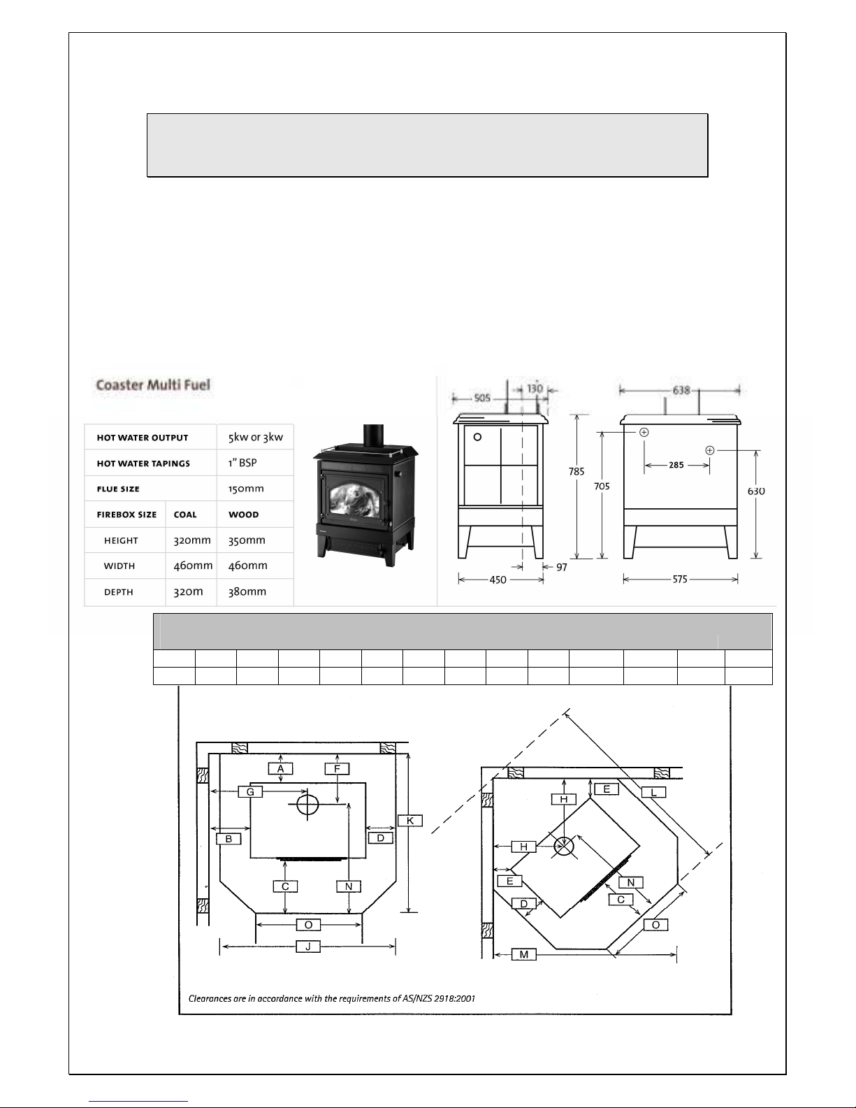
1. Position heater on floor protector ensuring all heater
clearances are correct as per clearances on page 5.
2. Once the location is confirmed, the appliance and floor
protector shall be fixed to the floor itself (refer to
page 6 & 7 .
3. Extend a plumb line from the centre of the fire flue pipe
spigot to the ceiling. Mark position on ceiling and roof.
4. Trim hole and nog as required ensuring that a 25mm
safe clearance between combustible materials and flue
components is maintained. Fix with non combustible
spacers and screws or clouts on all four sides.
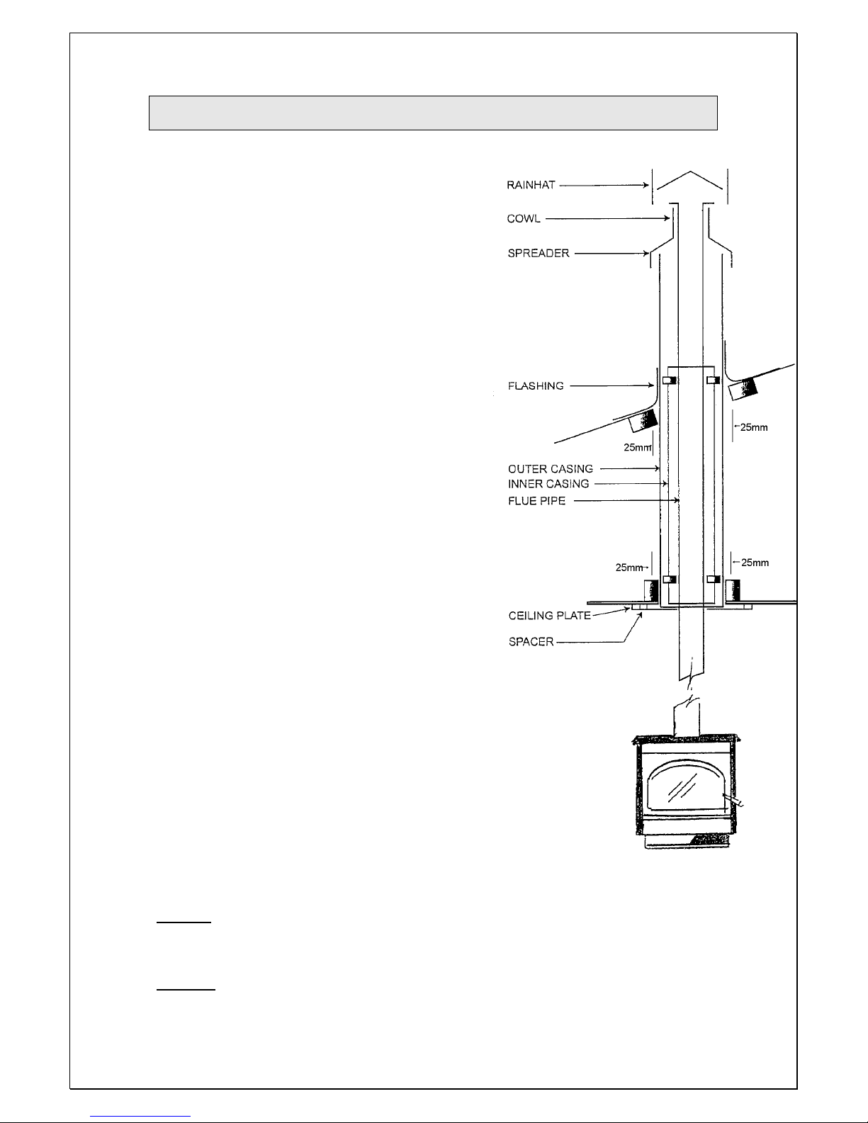
5. Cut and frame (when required an opening in the roof,
position the outer casing through the roof until it is flush
with the under side of the ceiling, making sure as with
the ceiling there is a 25mm safe clearance between
non-combustible materials and the flue components.
Fix as in step 4.
6. Fix appropriate flashing around outer casing to the
roof to ensure a weatherproof seal.
7. Assemble flue pipe sections ensuring all seams are in
line, the assembly is straight and crimped. Ends are
pointing downwards. Fix each joint with three stainless
rivets or self-tapping screws.
8. Place ceiling plate with folded edges upwards over
heater spigot.
9. Position the flue pipe into the heater spigot. The flue
pipe can either lowered from the top as a single unit or
fed up from the room a length at a time, ensuring that
all joints are fixed properly.
10. Slide the inner casing into place, between the outer casing
and the flue pipe.
11. The flue pipe must extend 200mm above the outer casing.
Note: Extra lengths of flue pipe, inner and outer casing
may be required to achieve the minimum clearance from
the roof.
12. Slide top spreader over flue pipe down into outer and inner
casing and tighten.
13. Slide cowl over flue pipe until it rests on spreader. Secure
with rivets or self-tapping screws.
14. Fit rainhat. Do not fasten as it must be removable for flue
pipe cleaning.
15. Fix ceiling plate to ceiling maintaining an even gap all around the flue pipe.
Note: Ensure ceiling plate is spaced off from the ceiling with ceramic spacers supplied.
16. Fit flue shield.
CAUTION: Mixing of appliance or flue system components from different sources or modifying the
dimensional specifications of components may result in hazardous conditions. Where such action is
considered the manufacturer should be consulted in the first instance.
WARNING: The appliance and flue system shall be installed in accordance with AS/NZS 2918:2001
and the appropriate requirements of the relevant building code or codes.

8
7. WETBACK
7. WETBACK7. WETBACK
7. WETBACK
The Coaster can be fitted with either a 3kwt or 5kwt wetback to supplement the hot
water system.
WARNING:
DO NOT CONNECT TO AN UNVENTED HOT WATER SYSTEM.
DO NOT U E THI FIRE WITHOUT WATER RUNNING THROUGH THE
WETBACK.
Care must be taken to protect the wetback coil and associated pipe work if being
installed in a hard/corrosive water area. Damage caused to the Wetback coil if
fitted in a hard/corrosive water area will not be covered under the
manufacturer’s warranty.
INSTALL IN ACCORDANCE WITH AS 3500.4.1 OR NZS 4603 AND THE
APPROPRIATE REQUIREMENTS OF THE RELEVANT BUILDING CODE OR
CODES.
For best performance apply the following rules:
1. Keep it simple with the shortest and straightest possible pipe run.
2. The heater should be within 6 metres of the hot water cylinder, the closer the
better.
3. Keep all flow pipes rising - the cylinder should be at least 300 mm above the
wet-back outlet.
4. Use only 25mm supply and return pipes.
5. Where possible the pipes should be insulated.

FIRENZO
WOODFIRE
BY
Hewitsons Limited
Manu acturers o :
Lady Kitchener
Contessa
Coaster
Bronte
Dante
Viking
Zealandia
Athena
Aqualux
Forte
Plaza
Deco
68 Austin treet
PO Box 3231
Onekawa
Napier 4142
Phone: 06 8438260
Fax: 06 8430505
Email: hothouse@firenzo.co.nz
Web: www.firenzo.co.nz
Table of contents
Popular Stove manuals by other brands

THERMOROSSI
THERMOROSSI PIDRA 18 Installation, use and maintenance guide

Avalon
Avalon Tree of Life GS2 owner's manual

Harman
Harman Clarity 929 DV Installation & operating manual

PENTAGAST
PENTAGAST cookmax CXE4F98Q operating instructions

Mendip Stoves
Mendip Stoves Ashcott Operation and instruction manual

Jøtul
Jøtul GF 160 DV IPI Installation and operation instructions

Heatilator
Heatilator ECOCHOISE CAB50-C owner's manual

EdilKamin
EdilKamin MILLA H 15 Up Directions for installation, use and maintenance

Diamond
Diamond E9/4PQF8 quick start guide

Belfort
Belfort 134 04 11 Technical manual

RIKA
RIKA Pico operating manual

Calux
Calux Uniflam Idro 24 kW Installation and instructions