Firestone 2097 User manual

INSTALLATION INSTRUCTIONS
Congratulationsonyourpurchaseofanew LevelCommand
kit. This kit was designed to provide inflation control of your
air helper springs. This kit will be an asset to your vehicle,
meeting nearly all of your air supply needs.
Please take a few minutes to read through the instructions,
identifythecomponents,andlearnhowtoproperlyinstallyour
Level Command kit.
NOTE:
The Level Command kit can be used with all air helper
springproducts. Ifyouareinstallinganairsuspensionsystem,
do not install the air line tubing to the air springs as stated in
the suspension system instruction manual. If you are adding
the Level Command kit to an existing air suspension system,
you will need to deflate the air springs and remove the air line
tubing.
NOTE ON CONNECTING THE AIR LINE TUBING:
Cut the air line tubing as squarely as possible. To connect
theairlinetubingtothefittings,pushthetubingintothefittings
asfaraspossible. Ifforanyreasonthetubingmustberemoved,
firstreleasetheairpressurefromtheairhelperspring. Pushthe
collartowardthebodyofthefitting and thepulloutthetubing.
To reassemble, make sure the tubing is cut squarely and push
the tubing back into the fitting.
TOOLS REQUIRED:
• 3/16" DRILL BIT • 3/8" DRILL BIT
• 1/4" DRILL BIT • POWER DRILL
• WIRE CRIMPER/STRIPPER • PLIERS
• PHILLIPS SCREW DRIVER • UTILITY KNIFE
• (2) 7/16" WRENCHES • CENTER PUNCH
0 150
30 120
60 90
200
400 600
800
1000
psi kPa
PSI
SINGLEAIRCONTROLPANEL 1
COMPRESSOR 9285 1
RELAYHARNESS 9307 1
30 FT. AIR LINE TUBING 1
STRAIGHTFITTING 3055 1
T-FITTING 3025 2
2097 / 2227
PARTS LIST
LEVEL COMMAND
10 -32 x 1" MACHINE SCREW 7
10-32LOCKNUT 7
#10FLATWASHER 14
RINGTERMINAL 1
WIRE CONNECTOR 2
NYLON TIE 15
PERFORMANCE SUSPENSION PARTS

BACK OF
CONTROL PANEL
FROM
COMPRESSOR
TO
AIR SPRINGS
CHECK VALVE

LOCK NUTS
WASHERS
MACHINE SREWS
CONTROL PANEL
BRACKET
WASHERS
STEP 1 - SELECT AMOUNTING LOCATION FOR THE CONTROL PANEL
Select a mounting surface under the dashboard or other protected
location. Using the control panel as a template, mark each of the
mountingpointswithacenterpunch. Drilla3/16"diameterholeoneach
center mark see Figure "B".Do not attach the control panel at this
time.
STEP 2-PREPARE THE COMPRESSOR
Install the push-to-connect male fitting into the check valve on the
compressor head see Figure "A". Tighten the fitting sufficiently to
engageat least twothreads withpre-applied orange thread sealant. DO
NOT OVERTIGHTEN THE FITTING.
STEP 3 - MOUNT THE COMPRESSOR
Begin by removing the negative battery cable. Select a convenient
locationtomountthecompressor. Thislocationshouldprovideampleair
flowandbeprotectedfromairbornedebrisandmoisture. Themounting
surfaceshouldberigidtosupportthecompressor,suchasunderthehood
on a fender well or in a vented storage compartment. The compressor
isoil-lessandcanbemountedinanyorientationnecessaryforinstallation.
Usingthecompressorasatemplateandacenterpunch,markanddrill
four 3/16"holes. Anyburrsintheholesshouldberemovedtoprevent
damagetotherubberisolators. Mountthecompressorusingthesupplied
10 -32 x 1" machine screws, 10 -32 lock nuts, and 3/16" washers see
Figure"C". Maximumvibrationisolationcanbeachievedbyproperly
mounting the compressor. The machine screw and nut should be
tightened only enough to bottom-out the brass insert see Figure "C".
DONOTOVERTIGHTEN.Overtightening will crushthe brass insert
and the rubber isolator, thereby reducing vibration isolation. Finally,
connect the black wire with the ring terminal from the compressor to a
suitableground.
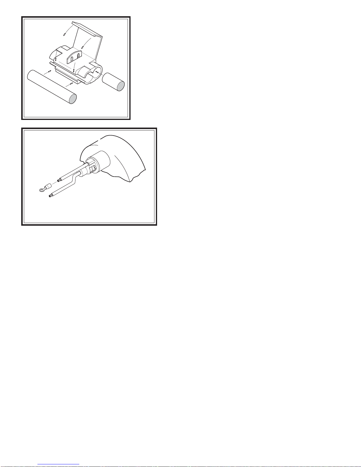
STEP 4 - ROUTE THE AIR LINE
Before installing the air line tubing, ensure that there is no pressure
intheairsprings. Toreleasetheairpressure,removethevalvecorefrom
the manual inflation valves or release the pressure by using a tire gauge
to depress the valve stem.
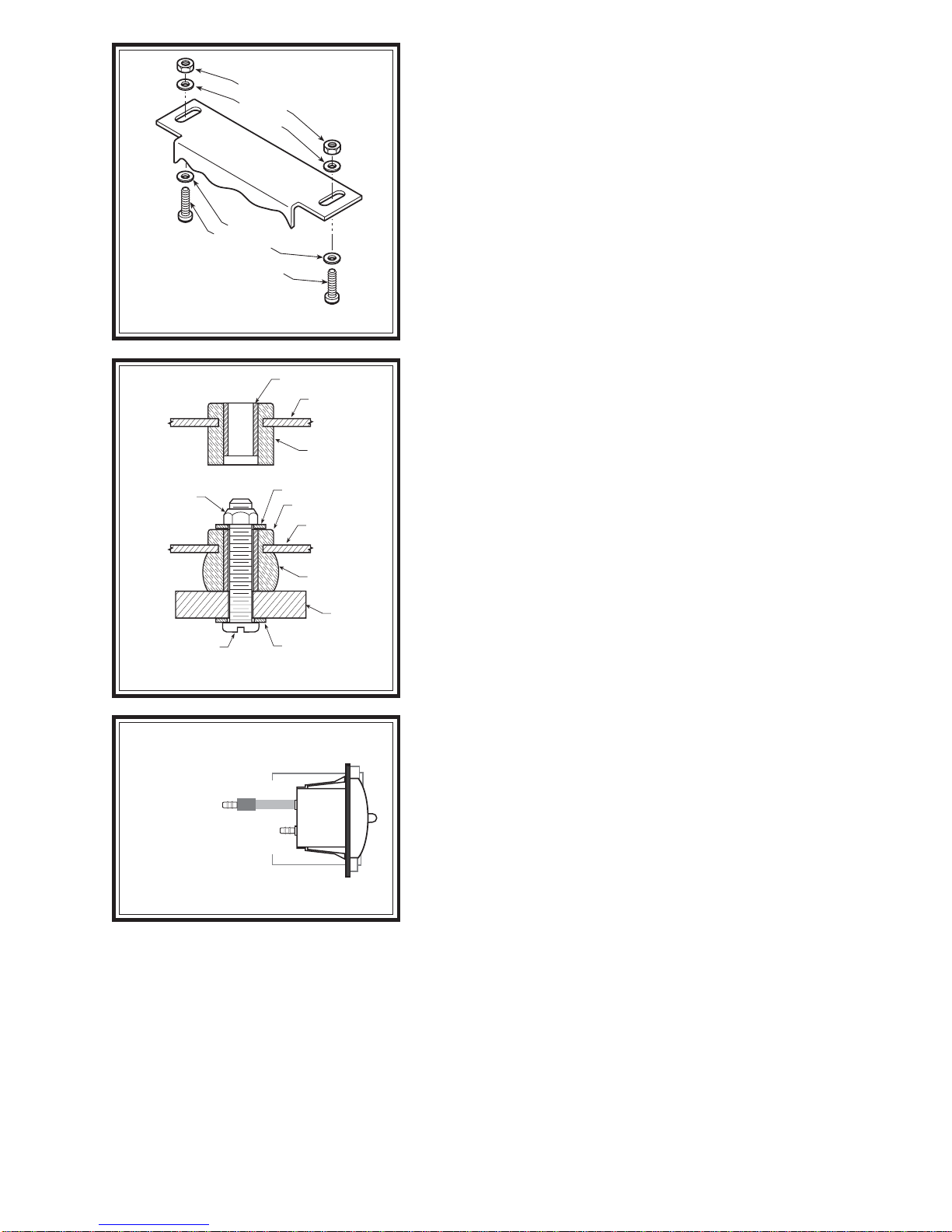
A) COMPRESSOR TO CONTROL PANEL
Cutapieceofair line tubing that will reach fromthe control panel to
thecompressor. Cuttheairlinetubingassquarelyaspossibleandinstall
thetubing ontothe barbedfittingonthe backofthe switchmarkedSUP
(supply) see Figures "A" & "D". Before attaching the air line tubing
tothecontrolpanel,soaktheend(1")oftheairlineinhotwaterforafew
minutes to soften the tubing. Do not use pliers to work the tubing on to
the barbed fitting, as the tubing may be damaged. It may be necessary
to drill a hole in the firewall to route the tubing. Donot foldorkinkthe
tubing.Ensure that the tubing is protected from sharp edges when
passing through the firewall.
B) CONTROL PANEL TO AIR SPRINGS
Cut a length of air line tubing that will reach from the control panel to the rear of the vehicle. Slide the tubing as
far as possible onto the barbed fitting on the back of the gauge, see Figures "A" & "D". Do not use pliers to work
the tubing on to the barbed fitting, as the tubing may be damaged. Install a T-fitting on the opposite end of the tubing
at the rear of the vehicle. Route a length of air line tubing from the T-fitting to each air spring. Use the suppled nylon
ties to secure the tubing to the vehicle. Make sure that the tubing is protected from sharp edges when passing through
the firewall.
STEP 6 - ATTACH THE CONTROL PANEL TO THE DASHBOARD
Place the air control panel on the dash where the holes were drilled in Step 1. Using the provided machine screws,
lock nuts, and washers attach the air control panel to the dashboard or selected mounting surface see Figure "B".
Figure "B"
Figure "C"
Figure "D"
BRASS SLEEVE
COMPRESSOR
FOOT
RUBBER
ISOLATOR
BRASS SLEEVE
COMPRESSOR
FOOT
RUBBER
ISOLATOR
#10 FLAT WASHER
#10 FLAT WASHER
VEHICLE
MOUNTING
SURFACE
#10 -32 LOCK
NUT
#10-32 x 1 PAN HEAD
SCREW
SIDE VIEW OF CONTROL PANEL
SUP
DEL
TO AIR SPRINGS
BARB FITTING
FROM COMPRESSOR

BACK OF
GAUGE
RING
CONNECTOR
(TO GROUND)
POSITIVE WIRE
(TO DASHBOARD
ILLUMINATION WIRE)
STEP 7 - ROUTE THE ELECTRICAL WIRE
Install the relay within three feet of the compressor. Nylon ties
can be used to secure any excess wire and the relay neatly into
place. Route the white wire labeled “Switch Panel” to the control
panel. Connect the white wire to one of the white wires on the back
of the switch. The remaining white wire will be grounded to the
vehicle. Next, connect the orange wire labeled “Comp +” to the red
(positive) wire on the compressor. Connect the red, fused wire
labeled "Bat +" from the relay to the battery or another 12V (posi-
tive) source capable of supporting 20 amps. See Figure "A".
STEP 8 - WIRE THE CONTROL PANEL FOR ILLUMINATION
Therearetwo wires on the backofthegauge; Connecttheonewire
to a fused dashboard illumination wire. Connect the other wire to a
suitable ground source see Figure "F".
Attach the end of the positive wire to a dashboard
illumination wire using a wire connector. Slip the wire
connector over the existing dashboard illumination wire and
inserttheun-strippedgaugepanelwireintothewireconnector.
Close the wire connector over the wires with pliers, see
Figure "E". Attach the other wire to a ground source by
crimping a ring connector on to the wire and securing it to a
suitable ground source on the vehicle. Note: Should
additional wire be necessary to reach the dashboard
illumination wire and ground source, use 16 gage multi-
strand wire.
STEP 9 - CHECK THE SYSTEM
With the Level Command kit and your air helper springs
installed, you are ready to test the system. Reattach the
negative battery cable. Turn on the vehicle's ignition. Push
thepaddleswitchuptoinflatetheairsprings. Thegaugewilldisplayhowmuchairpressureisintheairsprings. Inflate
theairhelperspringsto70psiORthemaxoperatingpressurefortheairsprings,whicheverisless,andcheckthefittings
for air leaks with an applied solution of soap and water. If a leak is detected at a tubing connection, check to make
sure that the tube is cut as square as possible and that it is pushed completely into the fitting. The tubing can easily be
removedfromthefitting. First, release the pressure from the air spring. Push thecollartowardsthebodyofthefitting
and pull out the tube.
Note:Ifitisnecessarytoremovetheairlinefromoneofthebarbedfittings,useashavingmotionwithasharpknife
to shave the air line until it is thin enough to pull off of the barbed fitting. DO NOT cut, scrape, or damage the fitting
or it may cause a leak path.
NOTE: If the system inflates the air springs normally but only releases the air pressure in the line and not
the air springs, the air lines are not properly installed on the switch and gauge. Switch the air lines making sure
the line from the air spring is connected to the gauge, and the line from the compressor is connected to the "SUP"
fitting on the switch.
SYSTEM OPERATION
TheLevelCommand kit allows theair springs to beinflated from the insideof the vehicle. Push thepaddle switch
up to inflate the air springs and push the paddle switch down to deflate the air springs.
Figure "E"
Figure"F"
WIRE FROM
PANEL LIGHT
CONNECTING WIRE
PLASTIC
CONNECTOR
This manual suits for next models
1