manuals.online logo
Brands
  1. Home
  2. •
  3. Brands
  4. •
  5. Parker
  6. •
  7. Control Unit
  8. •
  9. Parker SC Series Reference manual

Parker SC Series Reference manual

Service Bulletin 33-00C August 2005 Installation, Service and Parts Information
FEATURES
• Pilot Operated
• Interchangeable Capacity Cartridges Same
as Used on (S)PORT EPR’s
• Low Pressure Drop
• Manual Opening Stem
• All Service from the Top
• Sweat-in-place Without Disassembly
• Maximum Opening Pressure Difference
(MOPD): 20.7 bar (300 psig)
• Design Pressure (MRP): 31.0 bar (450 psig)
• Molded Class “F” Coil Construction
• Pilot Light Available
DESCRIPTION
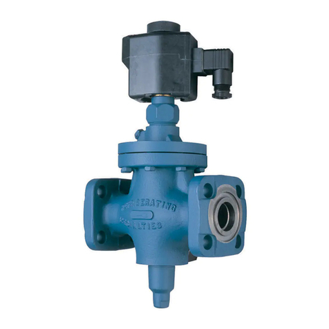
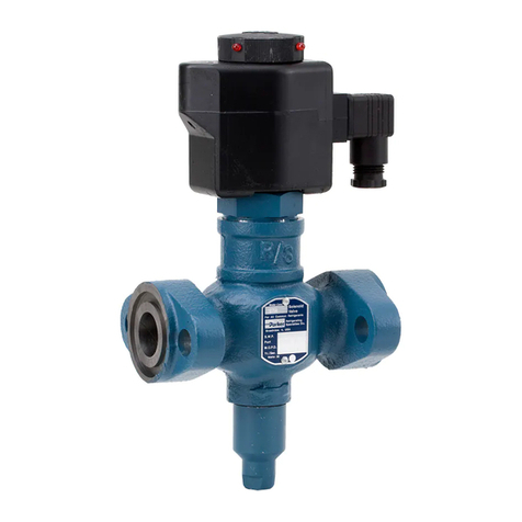
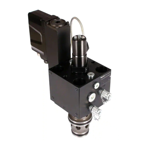
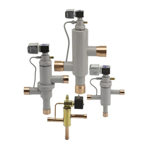
The new SC suction solenoid for commercial applications
was developed by the Refrigerating Specialties Division
of Parker Hannifin as an alternative low pressure drop
shut off valve in a wide range of both port and connection
sizes. With cartridge (port) sizes available as large as 2-
5/8”, SC solenoids are capable of handling greater flow
rates than other commercially available valves for suction
applications in a non-flanged design. In addition, this
unique design incorporates the same concept of cartridge
interchangeability as found in Parker’s popular (S)PORT
evaporator pressure regulators.
This innovative design actually utilizes the same capacity
cartridges (and valve bodies) as those used with the
(S)PORT regulator series, as well as the same solenoid
actuator, solenoid coil, and splice box coil housing.
Capacity cartridges can be changed by simply unscrewing
the valves’ four bonnet bolts in order to remove the
adapter and cartridge assemblies. With this flexible line
of solenoid valves now supplementing the existing line of
ISO 9001-2000 CERTIFIED
Figure 1
(S)PORT regulators having these same characteristics, a
single reliable source for all suction line components is
now available.This ductile iron-bodied solenoid valve with
brazed copper couplings is suitable for most common
refrigerants, certain oils and other fluids approved for use
in refrigeration. This valve may be opened by means of a
manual opening stem for servicing or in case of electrical
power failure. These solenoids are an integrated assembly
of (3) three modules: 1) A body containing no moving
parts; 2) A capacity cartridge, which contains both piston
and modulating plug, and 3) an adapter on which the pilot
solenoid is mounted and which incorporates a manual
opening stem which bypasses the pilot pressure around
the solenoid and directs it to the top of the valve piston.
ORDERING GUIDE
Parker’s SC solenoid series can be ordered using the
same numbering system which is used with (S)PORT
pressure regulators. The first two digits following the
“SC” valve type designate the valve’s port size in eighths
of an inch, while the second two digits designate the
connection size, also in eighths of an inch. For example, an
SC-07-09 would call for a 7/8” Port (or cartridge) size and
a 1-1/8” ODS connection. Both (S)PORT regulators and SC
solenoids are frequently ordered less coil and coil housing
for inventory purposes. Should a solenoid coil be desired
however, please indicate the voltage requirement when
ordering.
PRINCIPLES OF OPERATION
The R/S Type SC is a pilot operated solenoid. The valve
in its closed position, with the solenoid coil de-energized
and the plunger and piston plug in the seated position, is
shown in Figure 1. Electrical energizing of the solenoid
coil forms a magnetic field, pulling up the plunger, lifting
it off its seat. Upward motion of the plunger permits
entrance of the fluid from the valve inlet
SOLENOID Valve -- Type SC
Port Size 9 - 66mm (3/8” - 2-5/8”)
For , R12, R22, R502 and other common refrigerants
050414
2
Service Bulletin 33-00C August 2005
through the adapter and down through the pilot port to
the top of the piston. This forces the piston downward and
pushes the main port plug open, thereby permitting flow
of the refrigerant through the valve. The closing spring
meanwhile is held in a compressed position.De-energizing
of the solenoid coil permits the spring-assisted plunger
to reseat, stopping the flow through the pilot port. Bleed-
off, through the bleed hole in the piston, decreases the
pressure above the piston and allows the closing spring
to force the main port plug upward into a closed position
to stop the flow. The pressure difference across the valve,
acting upon the area of the valve seat, plus the force of
the closing spring, holds the main port plug in a tightly
closed position.
MANUAL OPENING STEM
The manual opening stem on the SC solenoid is for the
purpose of opening the valve without energizing the
solenoid coil. Refer to the exploded view and the parts
list for location of the stem and other related parts. For
access to the stem, the seal cap must be removed. This
must be done with caution as refrigerant may be trapped
inside the seal cap. Manual opening is accomplished
by turning the stem counter clockwise until stopped. To
reset for automatic operation turn stem clockwise until
seated.
INSTALLATION
The solenoid valve can be mounted in a horizontal or
vertical line with the flow in the direction of the arrow on
the valve body. Protect the inside of the solenoid valve
from moisture, dirt and chips during installation. These
valves may be soldered into the line without disassem-
bly. A wet cloth should be wrapped around the valve
and the soldering flame should be directed away from
the valve body.The SC solenoid valve must be installed
with the arrow on the valve body in the direction of flow
through the valve. If the valve is backwards, the flow will
not be stopped when the valve is electrically de-ener-
gized. Like all Solenoid Valves, the SC can stop flow only
in the direction from normal inlet to normal outlet (as
shown by the arrow on the body). If reversal of pressure
occurs in the system so the outlet pressure exceeds the
inlet pressure, the plug will be blown away from its seat
and reverse flow will occur. If a system has this type of
pressure reversal, a check valve such as Refrigerating
Specialties Division Type CK4A in series with the sole-
noid valve will prevent flow reversal. (The CK4A must be
installed downstream of the solenoid to avoid trapping
liquid when the solenoid is de-energized.)
ELECTRICAL
The Refrigerating Specialties Division molded water
resistant Class “F” solenoid coil, which is standard
on the SC solenoid, is designed for long life and pow-
erful opening force. The standard coil housing meets
NEMA 3R and 4 requirements. This sealed construction
can withstand direct contact with moisture and ice.
The Class “F” solenoid coil and splice box housing
should be used on low side applications only. Due to
the lower temperature rating of the Class “F” coil, it
should not be used with solenoid valves applied to high
side duty. For those applications, the Class “H” coil and
the general purpose housing should be used which are
standard on Parker Refrigerating Specialties Division
S81 and S82 solenoid valves.
A solenoid coil should never be energized except when
mounted on its corresponding solenoid tube.
The molded Class “F” coil is available from stock with
most standard voltages. However, coils are available for
other voltages and frequencies.
The solenoid coil must be connected to electrical line
with volts and Hertz same as stamped on coil. The
supply circuits must be properly sized to give adequate
voltage at the coil leads even when other electrical
equipment is operating. The coil is designed to operate
with line voltage from 85% to 110% of rated coil voltage.
Operating with a coil voltage above or below these limits
may result in coil burnout. Also, operating with a coil
voltage below the limit will definitely result in lower-
ing the valve’s maximum opening pressure differential.
Power consumption during normal operation will be
10.2 watts or less.
The coil housing washer (item #40) should be installed
on the solenoid operator (#36), before the coil housing
(#39) and the coil cover clip (#41) are installed.
This “Stack-up” maintains the coil firmly in place and
prevents excessive vibration of the entire coil housing
assembly when the coil is energized.
SERVICE POINTERS
1. Failure to Open: (a) Coil is of incorrectly high
voltage. See “Electrical”. Check voltage printed on the
coil. (b) Line voltage is abnormally low. See “Electri-
cal”. Check line voltage at coil leads with a voltmeter. (c)
Failure to electrically energize. Check control circuit. (d)
Pressure difference across valve is too high. The SC will
open against a maximum pressure difference across
the valve of 21 bar (300 psig). (e) Solenoid Coil is burned
out. See “Electrical”, and replace with proper coil. (f)
Plunger Assembly is sticking. To disassemble the SC
for inspection of internal parts (after pumping out the
system as required): disconnect power source to Sole-
noid Coil, remove (#36) Solenoid Operator Assembly,
then Adapter. Remove every trace of dirt from Adapter
and Cartridge Assembly. Thoroughly clean all parts and
reassemble using a light film of refrigerant oil.
2. Failure to Close: (a) Electrical control circuit
is not opening properly. Check wiring and controls. (b)
There are chips or dirt on the Pilot Seat or the Piston
Plug Seat , preventing proper seating.
3
Service Bulletin 33-00C August 2005
Repair Kits for SC1 and SC2 Solenoid Valves
Item No. Description Qty. SC1 3 thru 11 SC2 13 thru 21
6 Bolt Package 4 204677 204676
13,14,19,20,36,37 Adapter Assembly 1 204671 204670
15 Pin, Locating 1 N/A Separately
16 Body Assembly 1 N/A Separately
14,17,17A,18 Cartridge Kit (3/8”) - 03 1 204452 ------
14,17,17A,18 Cartridge Kit (5/8”) - 05 1 204453 ------
14,17,17A,18 Cartridge Kit (7/8”) - 07 1 204454 ------
14,17,17A,18 Cartridge Kit (1 1/8”) - 09 1 204455 ------
14,17,17A,18 Cartridge Kit (1 3/8”) -11 1 204456 ------
14,17,17A,18,26,30 Cartridge Kit (1 5/8”) - 13 1 ------ 207159
14,17,17A,18,26,30 Cartridge Kit (2 1/8”) - 17 1 ------ 207160
14,17,17A,18,26,30 Cartridge Kit (2 5/8”) - 21 1 ------ 207161
30 Items: 27,28,29 1 Only with cartridge kit
39,40,41
Coil and Housing Kit 120/60,
110/50 1 206004
Parker Hannifin Corporation  Refrigerating Specialties
2445 South 25th Avenue  Broadview, IL 60155-3858 USA
708.681.6300 FAX: 708.681.6306  www.parker.com/refspec
Service Bulletin 33-00C August 2005
Disassemble and clean Valve as outlined in 1(f) above. (c)
Piston Plug Seat or Pilot Seat may be worn or damaged
and therefore leaking. Disassemble and clean Valve as
outlined in 1(f) above. If any of these parts need replac-
ing, it is advisable to replace using the proper replace-
ment kit. (d) Manual Opening Stem is turned all or party
out and permitting flow through the valve.
3. Leakage through Valve: See (2) above.
WARRANTY
All Refrigerating Specialties Products are warranted
against defects in workmanship and materials for a pe-
riod of one year from date of shipment from the factory.
This warranty is in force only when products are proper-
ly installed, maintained and operated in use and service
as specifically stated in Refrigerating Special-ties Cata-
logs or Bulletins for normal refrigeration applications,
unless otherwise approved in writing by Refrigerating
Specialties Division. Defective products or parts thereof,
returned to the factory with transportation charges
prepaid and found to be defective by factory inspection
will be replaced or repaired at Refrigerating Specialties,
option, free of charge, F.O.B. factory. Warranty does not
cover products which have been altered or repaired in
the field; damaged in transit, or have suffered acci-
dents, misuse. or abuse. Products disabled by dirt, or
other foreign substances will not be considered defec-
tive. THE EXPRESS WARRANTY SET FORTH ABOVE
CONSTITUTES THE ONLY WARRANTY APPLICABLE
TO REFRIGERATING SPECIALTIES PRODUCTS,
AND IS IN LIEU OF ALL OTHERWARRANTIES, EX-
PRESS OR IMPLIED, WRITTEN OR ORAL. INCLUD-
ING ANY WARRANTY OF MERCHANTABILITY, OR
FITNESS FOR A PARTICULAR PURPOSE. No em-
ployee, agent, dealer or other person is authorized
to give any warranties on behalf of Refrigerating
Specialties, or to assume, for Refrigerating Spe-
cialties, any other liability in connection with any of
its products.
SAFE OPERATION (See Bulletin RSB)
People doing any work on a refrigeration system must
be qualified and completely familiar with the system
and the valves involved, or all other precautions will be
meaningless. This includes reading and understanding
pertinent product bulletins and the current Bulletin RSB
prior to installation or servicing work.
Type SC1 SC2
Connection
Size 22 mm 28 mm 35 mm 42 mm 54 mm 42 mm 54 mm 67 mm
A
Inch 9.6 9.6 9.4 9.9 11.1 11 12 13.5
mm 244 244 239 251 282 279 305 343
B
Inch 4.8 4.8 4.7 5 5.6 5.9 6.4 7.1
mm 122 122 119 127 142 149 162 181
C
Inch 0.8 0.9 1 1.1 1.2 1.1 1.4 1.7
mm 20 23 25 28 30 28 36 44
D
Inch 5.5 5.5 5.5 5.5 5.5 7.2 7.2 7.2
mm 140 140 140 140 140 183 183 183
E
Inch 6.9 6.9 6.9 6.9 6.9 9.4 9.4 9.4
mm 175 175 175 175 175 239 239 239
Bolt
Diameter
Valve
Size Torque
1/4” (6mm) 03-21
8ft lb (1.1
mkg)
5/16” (mm) 13-21
12 ft lb (1.7
mkg)
Jam Nut 13-21
8 ft lb (1.1
mkg)
Solenoid
Operator All
6 ft lb
(0.0mkg)

This manual suits for next models

2

Other Parker Control Unit manuals

Parker Sporlan LAC-4 Release note

Parker

Parker Sporlan LAC-4 Release note

Parker TDP Series User manual

Parker

Parker TDP Series User manual

Parker TDC Series User manual

Parker

Parker TDC Series User manual

Parker TPQ Series User manual

Parker

Parker TPQ Series User manual

Parker EP Series Pro-Bloc User manual

Parker

Parker EP Series Pro-Bloc User manual

Parker PACHC Series User manual

Parker

Parker PACHC Series User manual

Parker ASV5000 Series User manual

Parker

Parker ASV5000 Series User manual

Parker MI-101 Operating and maintenance instructions

Parker

Parker MI-101 Operating and maintenance instructions

Parker Autoclave Engineers 10V Series User manual

Parker

Parker Autoclave Engineers 10V Series User manual

Parker C10 User manual

Parker

Parker C10 User manual

Parker 20K User manual

Parker

Parker 20K User manual

Parker S7A Service manual

Parker

Parker S7A Service manual

Parker HASV08R User manual

Parker

Parker HASV08R User manual

Parker 810 Series Assembly instructions

Parker

Parker 810 Series Assembly instructions

Parker CK-6D User manual

Parker

Parker CK-6D User manual

Parker S5A-DN Operating and installation instructions

Parker

Parker S5A-DN Operating and installation instructions

Parker 221 Series User manual

Parker

Parker 221 Series User manual

Parker 71215 User manual

Parker

Parker 71215 User manual

Parker C2 Series Installation and maintenance instructions

Parker

Parker C2 Series Installation and maintenance instructions

Parker PHD Series User manual

Parker

Parker PHD Series User manual

Parker CM0504 User manual

Parker

Parker CM0504 User manual

Parker IQAN-LC5-C02 User manual

Parker

Parker IQAN-LC5-C02 User manual

Parker VA01 Series User manual

Parker

Parker VA01 Series User manual

Parker Series DFplus User manual

Parker

Parker Series DFplus User manual

Popular Control Unit manuals by other brands

jablotron AC-82 manual

jablotron

jablotron AC-82 manual

Ai-Thinker Technology ESP-32S user manual

Ai-Thinker Technology

Ai-Thinker Technology ESP-32S user manual

ABB ACSM1 Series Firmware manual

ABB

ABB ACSM1 Series Firmware manual

Gemu 8258 Installation, operation and maintenance instructions

Gemu

Gemu 8258 Installation, operation and maintenance instructions

NXP Semiconductors PMSMFRDMMCXN947 user guide

NXP Semiconductors

NXP Semiconductors PMSMFRDMMCXN947 user guide

Texas Instruments TPS2390EVM user guide

Texas Instruments

Texas Instruments TPS2390EVM user guide

Watts 900 Series quick guide

Watts

Watts 900 Series quick guide

Honeywell V4297A Series Product data

Honeywell

Honeywell V4297A Series Product data

TIL T3014 RF user guide

TIL

TIL T3014 RF user guide

GEM 0326 2M 74 41G4010810 operating instructions

GEM

GEM 0326 2M 74 41G4010810 operating instructions

Pentair TRACETEK TTDM-128 Installation instructions manual

Pentair

Pentair TRACETEK TTDM-128 Installation instructions manual

Dover OPW 623V Series Installation and maintenance instructions

Dover

Dover OPW 623V Series Installation and maintenance instructions

DSC PC6216 installation instructions

DSC

DSC PC6216 installation instructions

Stanley 71504 Instruction and service manual

Stanley

Stanley 71504 Instruction and service manual

ABB FSPS-21 user manual

ABB

ABB FSPS-21 user manual

Asco 552 Series Installation and maintenance instructions

Asco

Asco 552 Series Installation and maintenance instructions

Leviton SPLCH installation instructions

Leviton

Leviton SPLCH installation instructions

Stahl 9442/35-10-00 operating instructions

Stahl

Stahl 9442/35-10-00 operating instructions

manuals.online logo
manuals.online logoBrands
  • About & Mission
  • Contact us
  • Privacy Policy
  • Terms and Conditions

Copyright 2025 Manuals.Online. All Rights Reserved.