Fireye 60-2991 Series User manual

© 2021 Carrier 1
PFM-12
February 22, 2021
60-2991
BurnerPRO wiring harness to
replace HW RM7800 Series
control with BurnerPRO
Series
APPLICATION
The 60-2991-1 / 60-2991-2 adapter is used for connecting the BurnerPRO series flame safeguards to a Q7800F
wiring base. This allows replacement of the RM7800 series burner control system without having to perform
complete system rewiring. The mechanical adapter will allow removal of the existing RM7800 control and
replacement with the Fireye BurnerPRO. All wiring (including to the flame rod) will be maintained. The only
other component requiring replacement will be the UV scanner (if used).
FEATURES OF THE 60-2991 WIRING HARNESS
• Ease of installation
• Connection of UV scanner and/or flame rod
• Lockout retained through a power cycle (non-volatile)
• Proof-of-closure (fuel valve end switch) monitoring
• Air flow switch proving
• A check/run feature that allows the program sequence to pause in purge or PTFI
• Remote reset via line voltage input
• Smart LEDs that provide operational sequence, lockout information and flame intensity
• Modbus RTU communication via RS485 with read/write capability
• Small footprint: 4.15” (105mm) L x 4.15” (105mm) W x 5.0”(127mm) H
• Expert support from the Fireye team
This manual describes the installation, commissioning, operation and maintenance of the 60-2991Wiring
Harness. It may be used in conjunction with the following other manuals:
• BP-1003 – BurnerPRO with UV and FR flame detector, Modbus communication and valve proving
system.
• SC-108 – UV scanners compatible with BurnerPRO flame safeguard system.
• SC-102 – Cenelec EExd IIC explosion proof housing with UV1AL3 scanner.
• SC-103 – Flame rods compatible with BurnerPRO flame safeguard system.
WARNING: Failure to properly install, operate, or commission the equipment in this manual could result in
significant property damage, severe injury, or death. It is the responsibility of the owner or user to ensure that
the equipment described is installed, operated and commissioned in compliance with this manual and other
system component manuals, as well with all applicable national and local codes.
© 2021 Carrier 2
WARNING!!!
Boiler operation, maintenance, and troubleshooting shall only be conducted by trained personnel. Persons troubleshooting
lockouts or resetting the control must respond properly to troubleshooting error codes as described in this product bulletin.
Jumpers being used to perform static test on the system must only be used in a controlled manner and must be removed
prior to the operation of the control. Such tests may verify the external controllers, limits, interlocks, actuators, valves,
transformers, motors and other devices are operating properly. Such tests must be conducted with manual fuel valves in
the closed position only. Replace all limits and interlocks not operating properly, and do not bypass limits in interlocks.
Failure to follow these guidelines may result in an unsafe condition hazardous to life and property.
TABLE OF CONTENTS
APPLICATION....................................................................................................................................................................1
FEATURES OF THE 60-2991 WIRING HARNESS.......................................................................................................... 1
CONTENTS.........................................................................................................................................................................2
SPECIFICATIONS
................................................................................................................................................................. 3
BURNERPRO SYSTEM SPECIFICATION
................................................................................................................................. 3
APPROVALS
.........................................................................................................................................................................5
PART NUMBERS AND APPROVALS .............................................................................................................................5
ORDERING INFORMATION............................................................................................................................................6
INSTALLATION PROCEDURE........................................................................................................................................6
WIRING CONNECTIONS..................................................................................................................................................7
TIMING ............................................................................................................................................................................. 13
FLAME SCANNERS
............................................................................................................................................................. 16
NOTICE............................................................................................................................................................................. 19
WARRANTIES.................................................................................................................................................................. 19
© 2021 Carrier 3
SPECIFICATIONS
MODEL:
60-2991-1: HW RM7800 series burner controls with modulating motor control (RM7800/RM7840/RM7845 less
valve proving).
60-2991-2: HW RM7800 series burner controls with on/off motor control (RM7895).
BURNERPRO SYSTEM SPECIFICATION
Supply Voltage:
BP110 110 VAC (+20%, -15%) 50/60 Hz, single phase
Power Consumption:
7 VA
Temperature Rating:
Operating: -40°C to +60°C (-40°F to 140°F)
Storage: -50°C to +85°C (-58°F to 185°F)
Flame Amplifier Rating:
UV: Terminals 22 & 23, 300VDC/ 3mA
FR: Terminals 24 & Earth, 330VAC (max), 3uA min/10uAmax flame current
Protection Category:
IP40 standard version
Control Dimensions:
With wiring base (60-2981-1 or -2); 4.15” L x 4.15" W x 5.0" H (105mm x 105mm x 127mm)
Shipping Weight:
Approx. 1.3 lbs. (0.6 kg)
Relative Humidity:
90% R.H. (Non-Condensing)
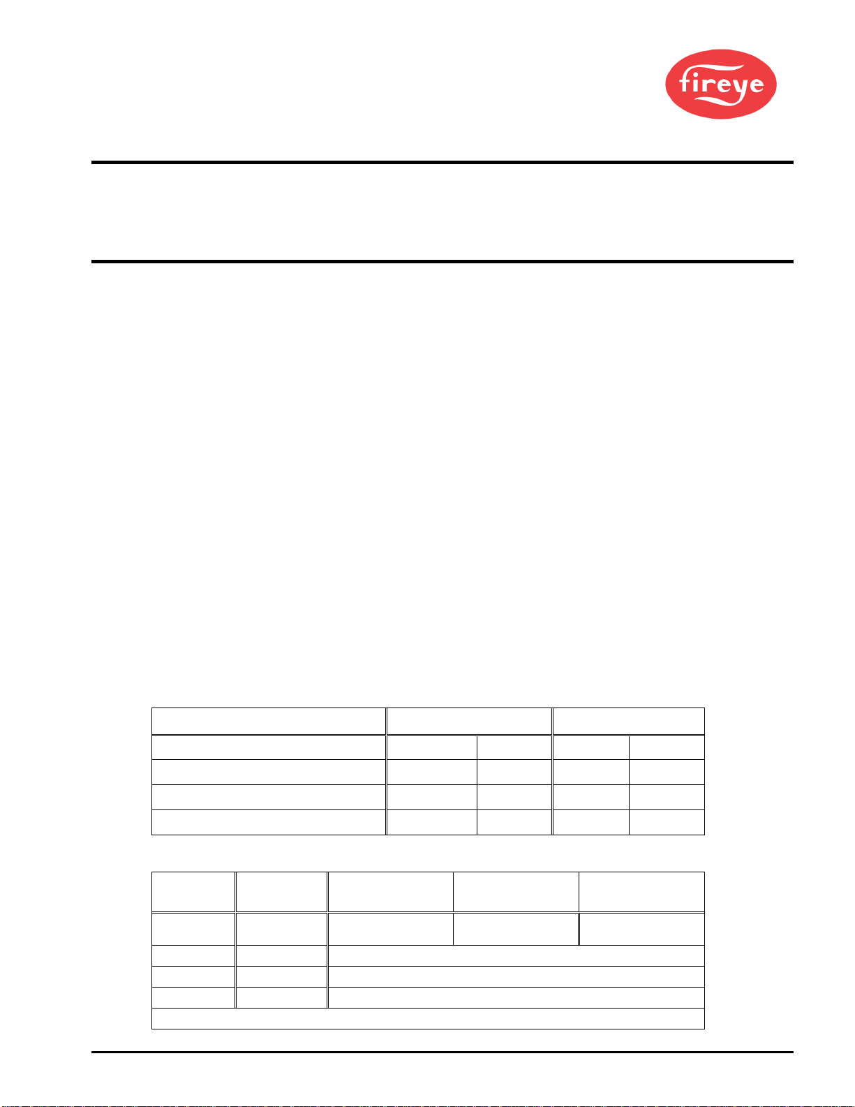
OPERATING TEMPERATURE LIMITS
CONTROL MAXIMUM MINIMUM
BP110 140°F 60°C -40°F -40°C
UV90L-1 194°F 90°C -40°F -40°C
UV1AL-3, -6 200°F 94°C -40°F -40°C
UV5-1, UV5-2 140°F 60°C -4°F -20°C
LOAD RATINGS:
Terminal Typical Load Maximum Rating
@120V-50/60 Hz
Maximum Rating
@230V-50/60 Hz
Alternate Rating
6-7 Burner/Blower
Motor
2 F.L.A. *
8 L.R.A.
2 F.L.A. *
8 L.R.A.
240 VA Pilot Duty
(Motor Starter Coil)
9-10-11-20 Modulator 240 VA Pilot Duty
16-17-18-19 Fuel/Ignition 240 VA Pilot Duty
3 Alarm 125 VA Pilot Duty
*
F.L.A. =
full
load amps; L.R.A = locked rotor
amps
Maximum connected load must not exceed 2000VA.

© 2021 Carrier 4
ELECTRICAL
RATINGS
VA ratings (not specified as pilot duty) permit the connection of transformers and similar devices whose
inrush current is approximately the same as their running current.
VA pilot duty ratings permit the connection of relays, solenoid valves, lamps, etc. whose total operating
load does not exceed the published rating and whose total inrush does not exceed 10 times the rating.
Running and locked rotor ratings are intended for motors. VA and VA pilot duty loads may be added to a
motor load provided the total load does not exceed the published rating.
OPERATIONAL
TIMINGS
The BurnerPRO is pre-programmed from the factory with a set of operational timings necessary for the
safe operation of the burner system. However, operational timings can be modified via the Modbus port
using the 60-3000 ModBus Comms cable and BP-CON configuration software. The operational timings
are governed by regional and local codes. It is important that the appropriate operational timing is selected
for the burner application.
DIMENSIONS: FIG. 1
In Inches or [mm]

© 2021 Carrier 5
APPROVALS
Underwriter’s Laboratories Inc.:
File MCCZ.MP1537
Controls, Primary Safety
File MCCZ7.MP1537
Controls, Primary Safety Certified for Canada
PART NUMBERS AND APPROVALS
Table 1: Agency Approvals
Fireye Part Number
60-2991-1 X
60-2991-2 X
BP110UVFR-S11M X
BP110UVFR-S12M X
BP110UVFR-S13M X
BP110UVFR-S14M X
X = CERTIFICATION IN HAND

© 2021 Carrier 6
ORDERING INFORMATION
60-2991-1 Wiring harness to convert RM7800/RM7840/RM7845 (less valve proving) to Fireye BurnerPRO
60-2991-2 Wiring harness to convert RM7895 to Fireye BurnerPRO
60-3000 USB to RS485 cable kit to communicate/configure BurnerPRO ModBus versions. Includes 60-2998
CONTROLS
BP110UVFR-S11M BurnerPRO, Single Modulating Gas Burner Control, 110VAC 50/60Hz, User Defined Timings, UV and FR amplifiers, Modbus
BP110UVFR-S12M BurnerPRO, Single Modulating Oil Burner Control, 110VAC 50/60Hz, User Defined Timings, UV and FR amplifiers, Modbus
BP110UVFR-S13M BurnerPRO, Single On/Off Gas Burner Control, 110VAC 50/60Hz, User Defined Timings, UV and FR amplifiers, Modbus
BP110UVFR-S14M BurnerPRO, Single On/Off Oil Burner Control, 110VAC 50/60Hz, User Defined Timings, UV and FR amplifiers, Modbus
SCANNERS
UV90L-1 UV scanner, front and side viewing, terminal block
UV5-1 UV scanner, side viewing, 78” (2000mm) flying leads
UV5-2 UV scanner, side viewing, quick disconnect connector
UV1AL-3 UV scanner, 1/2” NPT, 36” (915mm) shielded leads
UV1AL-6 UV scanner, 1/2” NPT, 72” (1830mm) shielded leads
4-742-1 Replacement tube for UV90L-1
UV1AL-CEX Cenelec Exd IIC explosion proof housing with UV1AL-3 scanner
INSTALLATION PROCEDURE
WARNING:
Disconnect power supply before beginning installation to prevent electrical shock and equipment damage.
More than one disconnect may be involved.
1. A UL listed flame safeguard system is comprised of the following items:
a) 60-2991-1 or 60-2991-2 wiring harness
b) BP110UVFR-S11M, BP110UVFR-S12M, BP110UVFR-S13M or BP110UVFR-S14M to match the
functionality of the unit being replaced
2. Wiring must comply with all applicable codes, ordinances and regulations.
3. Wiring must comply with NEC Class 1 (line voltage) wiring.
4. To minimize interference from radio frequency generated by the BurnerPRO, it is necessary that all control
wiring be placed in conduit.
5. Limit switches, interlocks and relay outputs must be rated to simultaneously carry and break current to the
ignition transformer, pilot valve(s) and main fuel valve(s) of the BurnerPRO.
6. Recommended wire routing of lead wires:
a) Do not run high voltage ignition transformer wires in the same conduit with any other wires.
b) Do not route analog transducer cables, display communication cables, Modbus cables or servo motor
cable in conduit with line voltage circuits. Use separate conduit where necessary.
© 2021 Carrier 7
7. Maximum wire lengths:
a) Terminal inputs (operating limits, interlocks, valves, etc.): 200 feet (61 meters).
b) Remote reset line voltage input: 500 feet (152 meters) NOTE: A normally open remote reset pushbutton
should be used and must remain within sight and sound of the burner.
c) Modbus via RS-485: 1000 feet (305 meter).
8. A good grounding system should be provided to minimize the effects of poor quality AC voltage. A
properly designed grounding system meeting all the safety requirements will ensure that any quality
problems (spikes, surges or impulses) have a low impedance path to ground. A low impedance path to
ground is required to ensure that stray currents paths created will drain to ground instead of through
equipment and causing potential damage.
9. Failure to follow these instructions can cause a hazardous condition and/or equipment damage.
10. Before installation, ensure that the control is suitable for your application by verifying all ratings and
functionality.
11. After installation, verify all control operation as provided in these instructions.
Published load ratings assume that the internal contacts will only get switched once every 15 seconds.
Using inputs which exceed this duty cycle can lead to premature control failure. Following the
tripping of a circuit breaker, a blown fuse or any known instance of excessive contact cycling, the
control should be operated with the fuel shut off as a test to ensure proper functionality.
WIRING CONNECTIONS
CAUTION: Ensure that electric power is turned off. Refer to SN-100 for recommended
grounding techniques. Be aware that power to some interlocks (operating controls, air
flow switches, modulating circuits, etc.) may be derived from sources other than what is
controlling the BurnerPRO.

© 2021 Carrier 8
60-2991-1 Wiring
Honeywell Term Function BurnerPro Term
4 Line Voltage Supply 1 & 4 1
L2 Line Voltage Common 2
F Flame Rod 224
G Flame Rod Ground Earth Ground
UV Scanner 222 2
UV scanner 223 2
6 Operating Control & Limits 5
20 Proof of Closure Valve 12
7 Running Safety Interlock (Air Flow) 3143
10 Ignition Transformer 16
8 Interrupted Pilot Fuel Valve 17
21 Intermittent Pilot Valve 18
9 Main Fuel Valve 19
5 Blower Motor 6
18 Low Fire Start Switch 8
19 High Fire Start Switch 15
3 Alarm 3
12 High Fire Internal relays 4
13 Common Internal relays 4
14 Low Fire Internal relays 4
15 Auto Internal relays 4
22 Shutter Not used
1 Terminal 4 is internally jumpered to terminal 1 via the BurnerPro control.
2If the Honeywell control used a non-self check UV scanner, then the Honeywell scanner must be removed and the Fireye UV
scanner must be wired into terminals 22 and 23 on the BurnerPro wiring base.
3The BurnerPro will lockout when the Running Safety Interlock circuit opens (RM7800L)
4 The BurnerPro outputs 120 VAC to the Mod Motor circuit. The 60-2991-1 adapter provides relays to simulate the dry contact
Mod Motor outputs of the RM7800.

© 2021 Carrier 9
60-2991-2 Wiring
Honeywell Term Function BurnerPro Term
5 Line Voltage Supply 1 & 4 1
L2 Line Voltage Common 2
F Flame Rod 224
G Flame Rod Ground Earth Ground
UV Scanner 222 2
UV scanner 223 2
6 Operating Control & Limits 5
7 Running Safety Interlock (Air Flow) 314 3
10 Ignition Transformer 16
8 Interrupted Pilot Fuel Valve 417 4
9 Main Fuel Valve 18
4 Blower Motor 6
3 Alarm 3
20 Proof of Closure 5 12 5
21 Delayed Main Fuel Valve 6Confirm - 18 6
1 Terminal 4 is internally jumpered to terminal 1 via the BurnerPro control.
2If the Honeywell control used a non-self check UV scanner, then the Honeywell scanner must be removed and the Fireye UV
scanner must be wired into terminals 22 and 23 on the BurnerPro wiring base.
3The BurnerPro will lockout when the Running Safety Interlock circuit opens. Jumper JR3 on the RM7895 selects recycle or
lockout.
4Terminal 17 on the BurnerPro provides interrupted operation of the pilot fuel valve. If intermittent operation is required, an
external jumper between terminals 17 and 19 on the BurnerPro wiring base must be added. The jumper could also be installed
between terminals 8 and 21 on the Honeywell wiring base. The timing of terminal 17 can also be programmed via Modbus for
continuous (intermittent) operation.
5Proof of Closure used on RM7897
6Delayed Main Valve used on RM7897C

© 2021 Carrier 10
The timings on the BurnerPro must match the timings as selected on the Honeywell RM7800 / RM7895.
Purge timing on the RM7800 is determined by which Honeywell ST7800A purge card is selected.
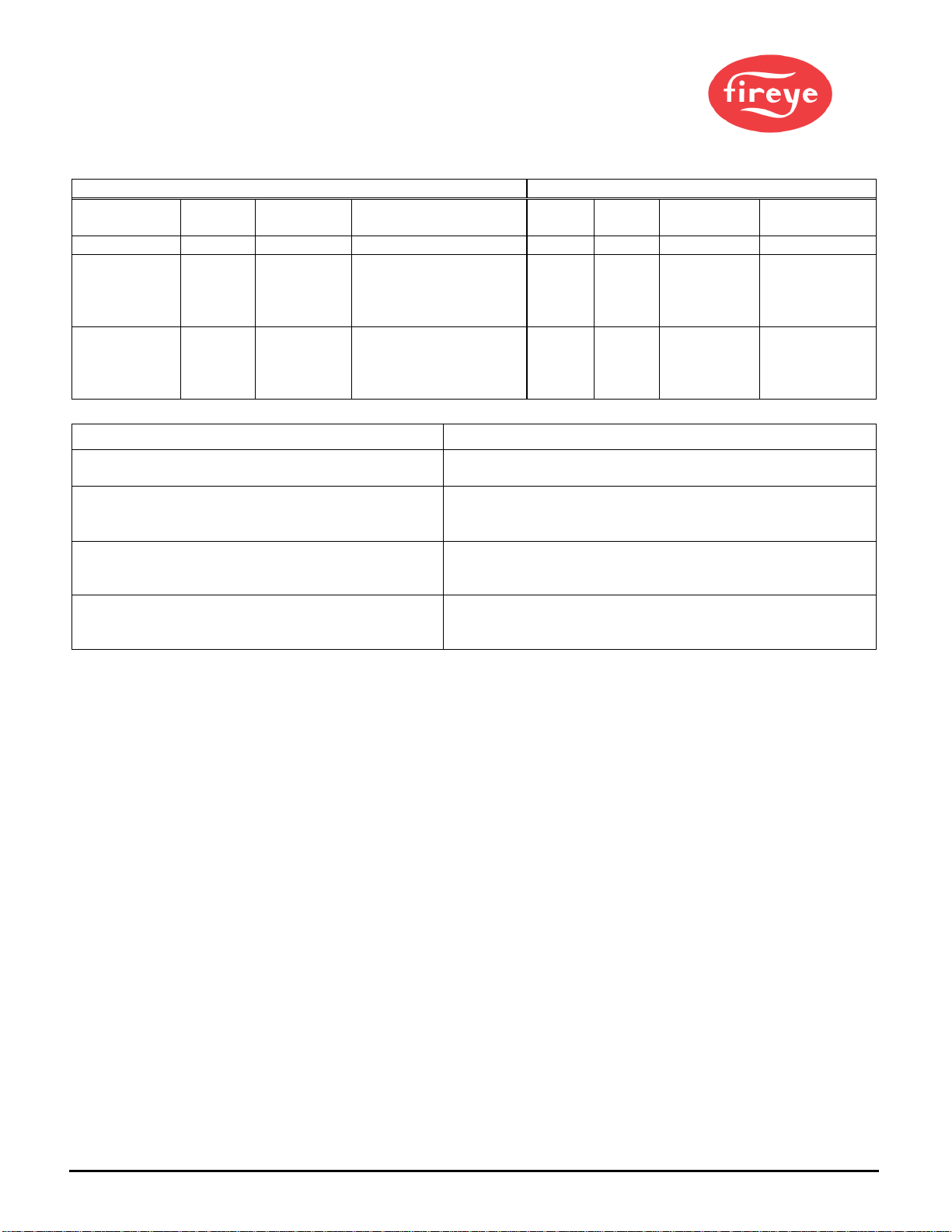
RM7800L Honeywell Terminals and Timings BurnerPro Terminals and Timings
Honeywell
Term PTFI MTFI Comments BP
term PTFI MTFI Function
10
5 sec
-
16
10 sec
-
Ignition
8 10 sec 10 sec 17 10 sec
S11M = 10
sec
S12M = 15
sec
Interrupted
Pilot
21 10 or 4
sec 15 sec
Jumper JR1 intact = 10
sec PTFI
Jumper JR1 clipped = 4
sec PTFI
18 - -
Intermittent
Pilot
Existing Honeywell RM7800L Installation Action
Firing Natural Gas / Light Oil– Ignition & Pilot on Term
8
Use S11M with defaults
Firing Heavy Oil – Ignition & Pilot on Term 21, JR
intact
Use S12M with defaults,
Move wire from Term 21 to Term 8 on Honeywell wiring base
Firing Heavy Oil – Ignition & Pilot on Term 21, JR
clipped Use S12M,
Change TSA / TSA’ to 5 sec,
Move wire from Term 21 to Term 8 o
n Honeywell wiring base.
Ignition on Term 10’ Pilot on Term 8
Change TSA / TSA’ to 5 sec, change t7 to 5 sec,
RM7800L 1053, RM7840L 1026 provide intermittent
operation on Term 21. Use S11M with defaults.
Install jumper wire from Term 8 to 21 on the Honeywell wiring
base.

© 2021 Carrier 11
RM7800G Honeywell Terminals and Timings BurnerPro Terminals and Timings
Honeywell
Term PTFI MTFI Comments BP
term PTFI MTFI Function
10
5 sec
-
16
10 sec
-
Ignition
8 10 sec 10 sec 17 10 sec
S11M = 10
sec
S12M = 15
sec
Interrupted Pilot
21 10 or 4
sec
15 sec, 30
sec, or
Intermittent
Jumper JR1 intact = 10
sec PTFI,
Jumper JR1 clipped - 4
sec PTFI
Jumper JR2 intact –
Intermittent
Jumper JR2 clipped – 15
sec MTFI
Jumper JR2 clipped,
Term 5 & 19 jumpered =
30 sec MTFI
18 - S11M = 10
sec
S12M = 15
sec
Intermittent Pilot
Existing Honeywell RM7800G Installation Action
Firing Natural Gas / Light Oil – Ignition & Pilot on
Term 8
Use S11M with defaults. Jumper Term 4 to 19 on MH wiring base
Firing Heavy Oil – Ignition & Pilot on Term 21, JR1
intact
Use S12M with defaults,
Move wire from Term 21 to Term 8 on Honeywell wiring base.
Jumper Term 4 to 19 on Honeywell wiring base.
Firing Heavy Oil – Ignition & Pilot on Term 21, JR1
clipped
Use S12M,
Change TSA’ to 5 sec,
Move wire from Term 21 to Term 8 on Honeywell wiring base.
Jumper Term 4 to 19 on Honeywell wiring base.
Ignition on Term 10, Pilot on Term 8 Use S11M.
Change TSA’ to 5 sec,
Change t7 to 5 sec,
Note: The BurnerPro will lockout when any Running Safety Interlock (e.g., air flow) opens. The RM7800G will attempt to
recycle.
© 2021 Carrier 12
RM7800M Honeywell Terminals and Timings BurnerPro Terminals and Timings
Honeywell
Term PTFI MTFI Comments BP
term PTFI MTFI Function
10
5
sec
-
16
10 sec
-
Ignition
8 10 sec 10 sec 17 10 sec
S11M = 10
sec
S12M = 15
sec
Interrupted
Pilot
21 10 or 4
sec Intermittent
Jumper JR1 intact = 10
sec PTFI,
Jumper JR1 clipped = 4
sec PTFI
18 -
S11M = 10
sec
S12M = 15
sec
Intermittent
Pilot
Existing Honeywell RM7800M Installation Action
Firing Natural Gas / Light Oil – Ignition & Pilot on
Term 8
Use S11M with defaults. Jumper Term 4 to 18 & 19 on MH
wiring base.
Firing Natural Gas or Heavy Oil – Ignition on Term 8,
Pilot on Term 21, JR1 intact Use S11M with defaults, move wire from MH Term 8 to Term 10.
Jumper Term 8 to 21 on MH wiring base.
Jumper Term 4 to 18 & 19 on
Honeywell
wiring base.
Firing Natural Gas or Heavy Oil – Ignition on Term 10,
Pilot on Term 21, JR1 clipped Use S11M with defaults, set TSA / TSA’ to 5 sec,
Jumper Term 8 to 21 on MH wiring base.
Jumper Term 4 to 18 & 19 on
Honeywell
wiring base.
Ignition on Term 10, Pilot on Term 8 Use S11M with defaults, set TSA / TSA’ to 5 sec,
Jumper Term 8 to 21 on MH wiring base.
Jumper Term 4 to 18 & 19 on
Honeywell
wiring base.
Note: The BurnerPro will lockout when any Running Safety Interlock (e.g., air flow) opens. The RM7800M will attempt to
recycle.
Note” The BurnerPro cannot replace the RM7800M with On – Off – On Firing Rate Circuit.

© 2021 Carrier 13
TIMING
BP110UVFR-
S11M
RM7800
BP110UVFR-
S12M
RM7800
BP110UV
FR-S13M
RM7895
BP110UV
FR-S14M
RM7895
PARAMETER Description GAS OIL GAS OIL
t1
Purge time
30s
30s
5s
5s
t3
Pre
-
ignition time (direct fired)
0
s
0
s
0s
0s
t3’
Pre
-
ignition time (piloted)
0
s
0
s
0s
0s
TSA Ignition safety time (directed
ignition)
10s 10s 5s 10s
TSA’
Ignition safety time (PTFI)
10
s
10s
5s
10s
t4 Interval between voltage on
pilot/ main fuel direct and main
fuel p
iloted
5s 5s 5s 5s
t4’ Interval between start of TSA
and the main fuel
p
iloted
5s 5s 5s 5s
t5 Interval between main fuel
piloted and release to modulation
15s 15s 15s 15s
t6
Post
-
p
urge time
15s
15s
5s
5s
t7
Pilot stabilization period
0s
0s
0s
0s
t9 Interval between main fuel
piloted and removal of pilot
(MTFI)
10s 14.9s 10s 14.9s
t11 Air damper running time to the
high fire
position
Optional Optional Optional Optional
t12 Air damper running time to the
low fire position
Optional Optional Optional Optional
t13 Permissible after burn time (post-
purge + 60 sec)
75s 75s 65s 65s
FFRT Flame failure response time
(FFRT)
4s 4s 4s 4s

© 2021 Carrier 14

© 2021 Carrier 15

© 2021 Carrier 16
FLAME SCANNERS
INSTALLATION - UV SCANNERS
Where possible, obtain the burner manufacturer’s instructions for mounting the scanner. This infor-
mation is available for most standard burners. The scanner mounting should comply with the follow-
ing general instructions:
1. Position the UV1AL, UV90L or UV5 scanner within 39 inches (1 meter) of the flame to be
monitored.
2. Select a scanner location that remains within the ambient temperature limits of the UV scanner.
3. The UVlAL scanner is designed to seal off the sight pipe up to 1 PSI pressure. Higher furnace
pressures must be sealed off. To seal off positive furnace pressure up to 50 PSI for the UV1AL
scanner, install a quartz window coupling (P/N: 60-1257). Add cooling air to reduce the scanner
sight pipe temperature.
4. Install the scanner on a standard NPT pipe (UV1AL: ½”) whose position is rigidly fixed. If the
scanner mounting pipe sights through the refractory, do not extend it more than halfway through.
Swivel flanges are available if desired (P/N: 60-302). The sight pipe must permit an unobstructed
view of the pilot and/or main flame, and both pilot and main flames must com- pletely cover the
scanner field of view.
SCANNER MUST HAVE
U
NOBS
TRUCTED
VIEW OF
FLAME
NOT THIS NOT
THIS
BUT THIS
FLAME MUST COMPLETELY
CO
VER
SIGHT
O
PENING
NOT
THIS
NOT
THIS
BUT TH
IS

© 2021 Carrier 17
5. Smoke or unburned combustion gases absorb ultra-violet energy. On installations with negative
pressure combustion chambers, a small hole drilled in the UV1AL sight pipe assists in keeping the
pipe clean and free from smoke. For positive pressure furnaces, provide clean air to pressurize the
sight pipe, if necessary.
6. Two UV1AL scanners may be installed on the burner if it is necessary to view two areas to
obtain reliable detection of the flame. They must be wired in parallel.
7. To increase scanner sensitivity with UV1AL scanner, a quartz lens permits location of the scanner
at twice the normal distance. Use 1/2” x 1 1/2” pipe nipple between UV1AL scanner and the
coupling.
8. Requesttheassistanceof any Fireyefield officeforrecommendationsof a properscannerinstallation
on a non-standard application.
TYPICAL UV SCANNER INSTALLATIONS
WIRING - UV SCANNERS
To connect the scanner to the control, the UV1AL scanner is supplied with UV1AL-3
(36") or UV1AL-6 (72") (0.9 m or 1.8 m) of flexible cable. The UV90L is supplied with
a terminal board. Use two #18 AWG conductors to connect the UV90L to the control.
The UV5 is supplied with 80” (2m) of flexible cable (detachable).
If it is necessary to extend the scanner wiring, the following instructions apply:
There is no polarity associated with the scanner wiring. Scanner wires must be installed in a separate
conduit. The wires from several scanners may be installed in a common conduit.
1. Selection of Wire
a. Wiring: For extended scanner wiring up to 500 feet (152 M), and for shorter lengths to reduce
signal loss, use a shielded wire (Belden 8254-RG62 coaxial cable, or equal) for each scanner
wire. The ends of the shielding must be taped and not grounded.
b. Avoid asbestos insulated wire.
c. Multi-conductor cable is not recommended without prior factory approval.
2. High voltage ignition wiring must not be installed in the same conduit with flame detector wires.
© 2021 Carrier 18
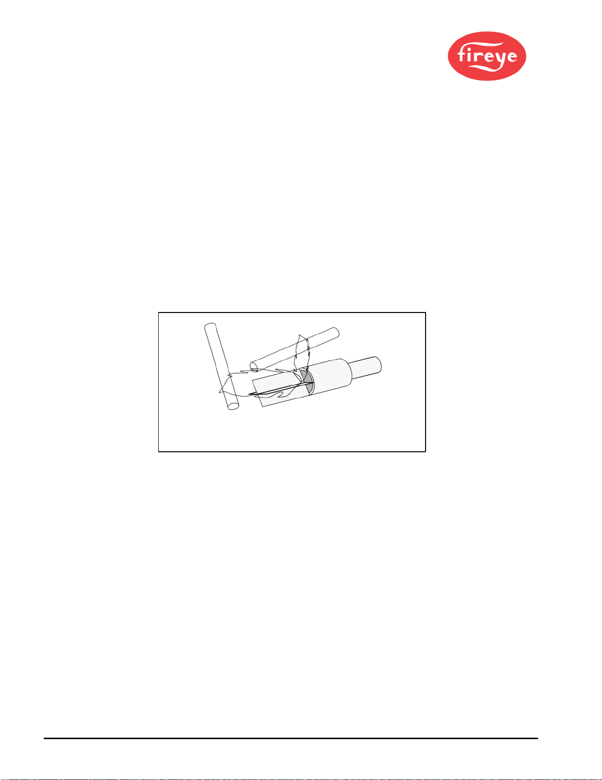
INSTALLATION - 69ND1 FLAME ROD
The 69NDl flame rod proves a gas pilot flame and/or main gas flame. It is a spark plug type unit. It
consists of 1/2' “NPT” mount, a KANTHAL flame rod, a glazed porcelain insulating rod holder and a
spark plug connector for making electrical connections. The 69ND1 is available in 12", 18" or 24"
(0.3m, 0.46m, 0.6m) lengths.
The flame rod may be located to monitor only the gas pilot flame or both the gas pilot and main gas
flames. Mount it with a l/2" “NPT” coupling.
The following instructions should be observed:
1. Keep your flame rod as short as possible.
2. Keep your flame rod at least 1/2" from any refractory.
3. Your flame rod must enter the pilot flame from the side so as to safely prove an adequate pilot
flame under all draft conditions.
4. If the flame is nonluminous (air and gas mixed before burning), extend the electrode tip at least
1/2" into the flame, but not more than halfway through.
WRONG POSITION
OF
ROD
CORRECT
POS
I
T
I
ON
OF
ROD
CORRECT
POSITI
ON
OF
PILOT FLAME
INADEQUATE
F
L
A
M
E
PILOT BURN
ER
5. If the flame is partly luminous, the electrode tip must extend only to the edge of the flame. It is
not necessary to maintain uninterrupted contact with the flame.
6. It is preferable to angle the rod downward to minimize the effect of sagging and to prevent it
from coming in contact with any object.
7. An adequate grounding surface for the flame must be provided. The grounding surface in actual
contact with the flame must be at least 4 times greater that the area of the portion of the flame rod
in contact with the flame. It is essential to adjust the flame rod and ground area ratio to pro- vide
a maximum, signal reading.
Note: Interference from the ignition spark can alter the true signal reading by adding to, or
subtracting from it. This trend sometimes may be reversed by interchanging the primary wires (line
voltage) to the ignition transformer. This interference can also be reduced by the addition of
grounded shielding between the flame rod and ignition spark.
8. Proven types of flame grounding adapters, as shown below, may be used to provide adequate
grounding surface. High temperature stainless steel should be used to minimize the effect of metal
oxidation. This assembly may be welded directly over the pilot or main burner nozzle.

© 2021 Carrier 19
WIRING - FLAME ROD
For proper operation of flame rectification systems, it is necessary to maintain at least 20 megohms
insulating resistance in the flame rectification circuit.
1. The scanner should be wired using metal cable or rigid conduit.
2. High voltage wiring must not be installed in the same conduit with scanner wiring.
SELECTION OF SCANNER WIRE
1. Use #14, 16, or 18 gauge wire with 90 C, 600 volt insulation for up to 20 feet distance.
2. The type of insulation used with flame rectification is important, since it must protect against
current leakage resistance to ground. Use Belden 8254-RG62 coaxial cable (or equal) for runs
greater than 20 feet. Maximum wiring run not to exceed 100 feet.
MAINTENANCE FLAME ROD
Type 69ND1 Flame Rod
1. The flame rod and its insulator should be kept clean by washing routinely with soap and water.
2. Rods should be routinely replaced as they oxidize.
Flame Signal Strength
Routine observation of the flame signal strength will forewarn any deterioration in the capability of
the flame detector or its application.
NOTICE
When Fireye products are combined with equipment manufactured by others and/or integrated into systems
designed or manufactured by others, the Fireye warranty, as stated in its General Terms and Conditions of
Sale, pertains only to the Fireye products and not to any other equipment or to the combined system or its
overall performance.
WARRANTIES
FIREYEguaranteesforoneyearfromthedateofinstallationor 18monthsfromdate ofmanufactureofits products
to replace, or, at its option, to repair any product or part thereof (except lamps, electronic tubes and photocells)
which is found defective in material or workmanship or which otherwise fails to conform to the description of the
product on the face of its sales order. THE FOREGOING IS IN LIEU OF ALL OTHER WARRANTIES
AND FIREYE MAKES NO WARRANTY OF MERCHANTABILITY OR ANY OTHER WARRANTY,
EXPRESS OR IMPLIED. Except as specifically stated in these general terms and conditions of sale, remedies
with respect to any product or part number manufactured or sold by Fireye shall be limited exclusively to the right
to replacement or repair as above provided. In no event shall Fireye be liable for consequential or special damages
of any nature that may arise in connection with such product or part.
FIREYE, Inc.
3 Manchester Road
Derry, New Hampshire 03038 USA
F
ireye.com
PFM-12
February 22, 2021
This manual suits for next models
2
Table of contents


