Fireye NEXUS FX04-1 User manual

1
®
DESCRIPTION
This bulletin describes the installation and operating instructions for the FX04 and FX04-1, 3 lb.-ft./
4Nm servo motors. .
SAFETY INFORMATION
WARNING: When this equipment is mounted onto an appliance, all external timers/control-
lers must be listed or recognized components and approved by national certification agencies
for the purpose for which they are used and approved for use by a local authority who has
jurisdiction.
The Fireye FX04 and FX04-1 servo motors are precision actuators designed to accurately position
valves and dampers. The servomotor interprets Modbus commands from an external control and
uses a stepper motor to drive to the commanded position. A feedback potentiometer provides contin-
uous positional information that can be read and cross checked by the external control.
The FX04 series servo motor offers a maximum output torque of 3lb.ft/ 4Nm with a minimum travel
time of 30 seconds for 90 degrees of rotation. Maximum rotation angle of the drive shaft is 100
degrees.
The servo is designed to be applied for fuel valves and air damper control on industrial burners. It
can also be applied to drive any type of flow control valve or damper as long as the output torque is
suited to the application.
Before attempting to install, commission or operate this equipment all relevant sections of this docu-
ment must be read and fully understood, failure to follow them could damage the product or cause a
hazardous condition. If in doubt about any requirements consult the supplier.
Check the ratings in the following instructions to ensure the product is suitable for your application.
Installation, commissioning or adjustment of this product MUST be carried out by personnel quali-
fied by local, state, regional or national requirements.
After installation is complete, check the product operation is as described in these instructions.
The manufacturer of this equipment accepts no liability for any consequences resulting from inap-
propriate, negligent or incorrect installation, commissioning or adjustment of operating parameters
of the equipment.
Note: The manufacturer of this equipment has a policy of continual product improvement and
reserves the right to change the specification of the equipment and the contents of this manual with-
out notice.
These mounting and operating instructions are intended to give the knowledge which is necessary to
carry out the mounting and adjustment of FX04 servo motor safely and correctly.
Fireye®NEXUS
FX04 and FX04-1
Servo Motor Installation
NEX-3004
JUNE 27, 2011
FX04-1
Shown
2
TECHNICAL DATA
Note 1: For FX04, FX20 and FX50, suitable conduit fittings that meet the desired protection are sup-
plied by the application.
ORDERING INFORMATION
SAFETY ADVICE
Device Safety
The servo motor must be used only for purposes corresponding to its construction and within the val-
ues specified in the technical data.
Actuating time for 90° angle of rotation: 30 s
Nominal torque: 3 lb.-ft./ 4 Nm
Holding torque: >3 lb.-ft./ 4 Nm
Max. revolutions on the output drive shaft: 100°
Nominal voltage 24 VDC~± 10%
Nominal power consumption: 5 VA
Angle of rotation limited by: Software
Degree of protection: NEMA 4 IP 65 (Note 1)
Installation position: Any
Working temperature range: 32°F - 140°F ( 0°C to + 60°C)
Duty cycle: 100%
Weight: 2.27 lb / 1.03 kg
Servos Bulletin
FX04 Servo motor, 24 VDC operation, 4Nm, 3 lb.-ft. torque, without connectors, accepts 1/2 inch
NPT fitting, minimum travel time of 30 seconds for 90° NEX-3004
FX04-1 Servo motor, 24 VDC operation, 4Nm, 3 lb.-ft. torque, with connectors, minimum travel time
of 30 seconds for 90°
FX20 Servo motor, 24 VDC operation, 20Nm, 15 lb.-ft. torque, without connectors, accepts
1/2 inch NPT fitting, minimum travel time of 30 seconds for 90° NEX-3020
FX20-1 Servo motor, 24 VDC operation, 20Nm, 15 lb.-ft. torque, with connectors, minimum travel
time of 30 seconds for 90°
FX50 Servo motor, 24 VDC operation, 50Nm, 37 lb.-ft. torque, without connectors, accepts
1/2 inch NPT fitting, minimum travel time of 30 seconds for 90° NEX-3050
FX-50-1 Servo motor, 24 VDC operation, 50Nm, 37 lb.-ft. torque, with connectors, minimum travel
time of 30 seconds for 90°
Servo Cables
59-565-6 Cordset, 6 feet, 1/2” NPT connectors on both ends, PVC jacket, temperature rating -40°C to
105°C, meets NEMA 1,3,4,6P and IEC67 133-748
59-565-40 Cordset, 40 feet, 1/2” NPT connectors on both ends, PVC jacket, temperature rating -40°C to
105°C, meets NEMA 1,3,4,6P and IEC67
Connector Kit
129-192 Connector, field wirable. Used for FX04-1, FX20-1, FX50-1 servos with connectors. Use
cable 59-565
133-747
59-565 Cable, twisted pair with drain wire, 2 power wires, suitable for servo hookup
3
®
The installer should be satisfied that, as a result of the mounting, the commissioning or as a result of
the test adjustments on the actuator, no potential hazards will be produced for devices/machines/
plant.
Before mounting the servo motor, check the free movement of the valve/device.
After completing the mounting and adjustment, check the correct functioning of the servo motor.
Safety advice for mounting and adjustments
The installer must be satisfied that, as a result of the commissioning or the test adjustments on the
servo motor, no potential hazards will be produced for personnel or the environment.
After completing adjustments check the correct functioning of the servo motor.
Check the correct functioning of any safety devices.
Carry out adjustments only in accordance with the instructions described in this documentation.
Adjustments must therefore be carried out only by a licensed electrician or a qualified person having
adequate training, who is aware of potential hazards.
Wiring
Five wires must be connected to power the servo. Cordsets are available for the FX04-1. Field
wirable connectors and cable are available for the FX04 (see page 5). Be sure to connect the ground
connection first to eliminate the ESD (electro static discharge) potential.
Use in a PPC4000 System
On a previously commissioned system, care must be taken when replacing a servo motor believed to
be defective. Although every effort is made to calibrate each servo, there may be slight differences
from servo to servo. It is strongly recommended the installer, equipped with a combustion analyzer,
use ADJUST RATIO to step through each profile that uses the replacement servo. Each profile set-
point should be checked and adjusted for proper combustion.
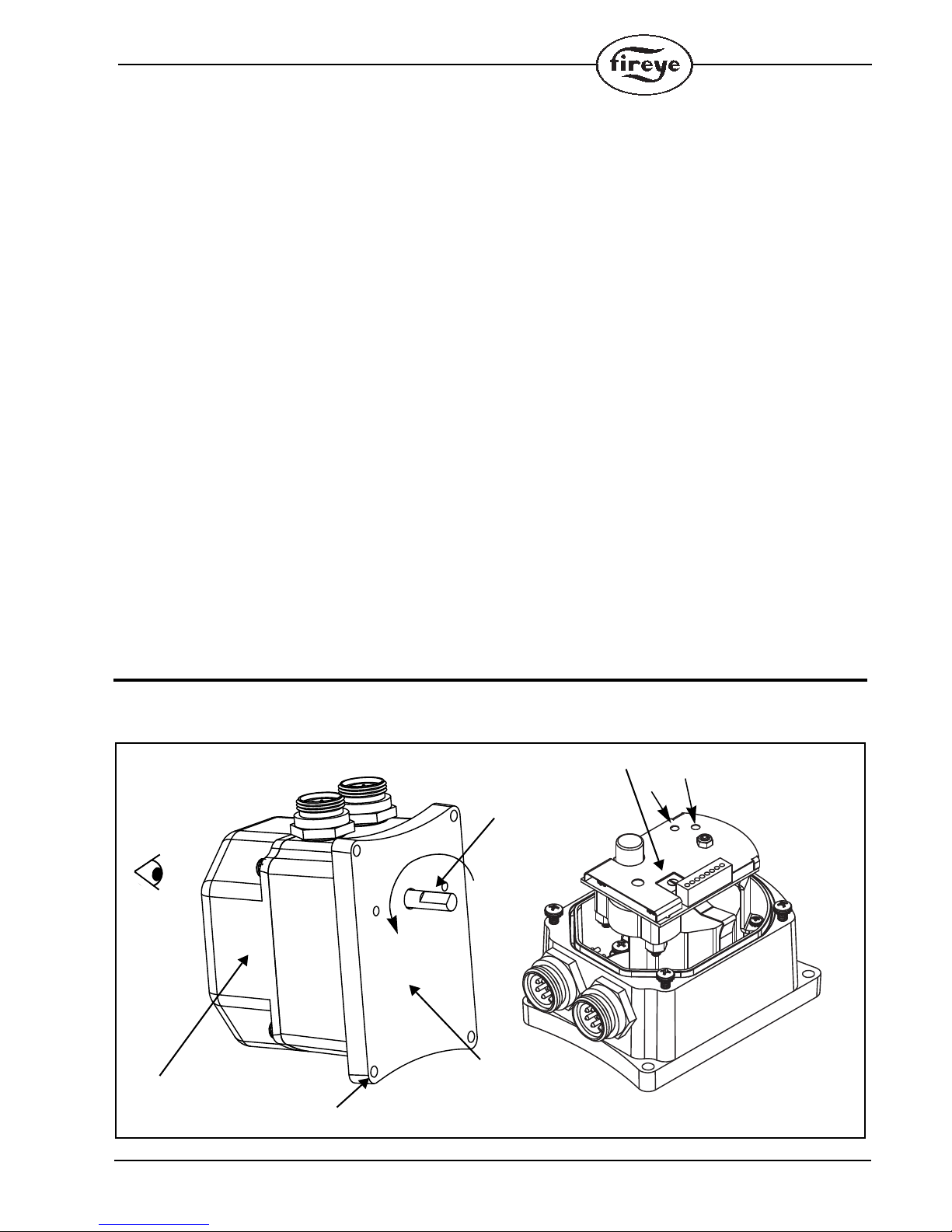
SERVO MOTOR DESCRIPTION
FIGURE 1.
UNIT ADDRESS
MANUAL MOVEMENT
MOUNTING SURFACE
OUTPUT SHAFT
PLASTIC COVER
MOUNTING HOLES (4) FX04-1 Shown
CCW
CW
0°
90°
clockwise
rotation shown
as viewed from
the cover side
4
INSTALLATION
Fasten the FX04 servo motor using bolts through a suitable mounting into the four 3/16 inch/5mm
mounting holes so that the mounting surface rests flat.
The output drive shaft should be connected using a suitable arm, link or flexible coupling.
The mounting position of the FX04 servo motor is arbitrary.
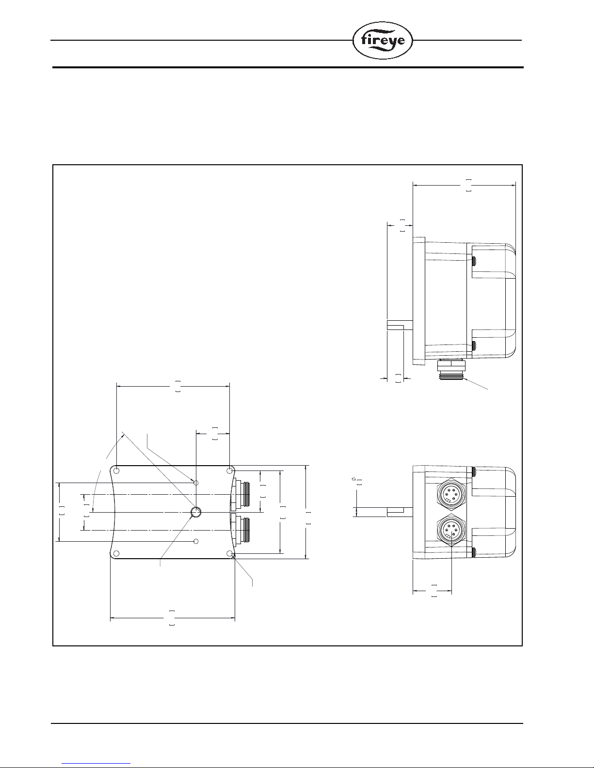
FIGURE 2. DIMENSIONS FX04 SERVO MOTOR
1.38
34.9
.32
8
4.47
113.5
3.27
83.1
4.054
103
2.897
73.6
1.20
30.5
1.45
36.8
2.05
52
M5 X 0.8 .281 DEEP
2 PLACES
1.25
31.8
45.0°
MOUNTING HOLES
FOR #10 SCREW
METRIC
WOODRUFF KEY
3.68
93.4
.919
23.4
.59
15
7/8-16UN THREAD

5
®
Cables, FX04-1
Cord sets having female connectors on both ends are available in 6 and 40 foot lengths.
Field wirable cables and connectors, FX04
Loosen the four cross-head housing cover screws and pull the cover hard to remove it. For the elec-
trical installation of the FX04 servo motor, use the prescribed cable type (corresponding to the envi-
ronmental conditions).
Feed cables through screwed cable entry via suitable conduit and glands and place the stripped ends
of the leads into screw connection terminals and terminate. Cable type 59-565 contains a drain wire,
and care should be taken when routing this to terminal 3. Tubing over the drain wire is recom-
mended. Wire ends should be properly stripped such that no bare wires protrude from the terminals
and thus produce the risk of a current surge or of a short circuit.
Store the cables such that they are not pinched when the housing cover is fitted or interfere with the
end travel switchcam mechanism or potentiometer coupling shaft.
Wiring information using 59-565
Terminal Color Description
1 Brown RS485 B(-)
2 Black 24 VDC
Return
3DrainEarth
Ground
4 Orange RS485 A(+)
5 Red 24 VDC
Power
Note: Brown and Orange are a twisted pair.
Red and Black are 18 AWG
59-565-6 or 59-565-40
1 1 4 4 2 2 5 5
3
3
Cable Entry
(suitable conduit
fitting required)
6
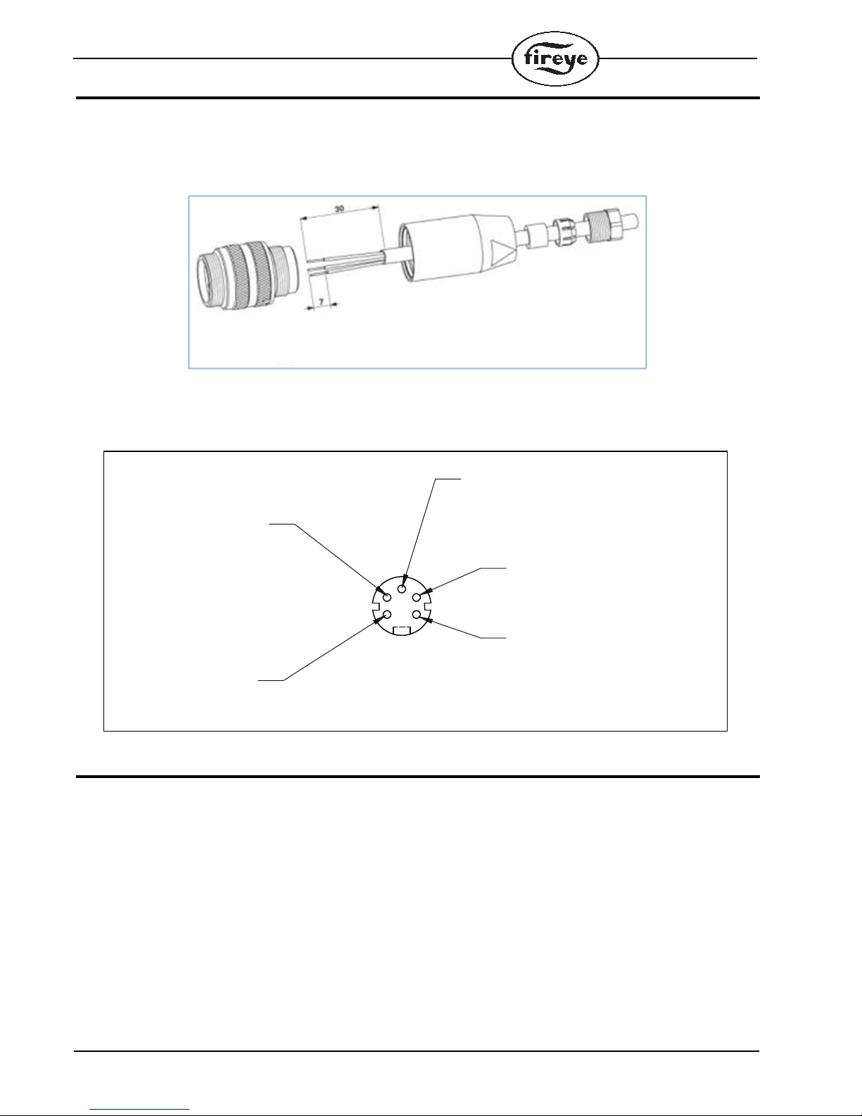
Cables and connectors
Field wireable connectors are available in kit form, 129-192. Fireye recommends cable part number
59-565 to be used for servo wiring. Fireye recommends cable part number 59-565 to be used for
servo wiring.
As shown above the cable strip length is specified at 30 mm (1.2 in) and each wire strip length is 7
mm (0.275 in).
To use cable 59-565, strip one end as specified. Strip each wire and wire to connector as shown.
ADJUSTMENTS/COMMISSIONING
Adjustments
Before the servo motor is opened or commissioned, the Safety Information and Safety Advice sec-
tions must be read.
Note: The cover must be removed to make the following adjustments.
Unit Address
The servos use a Modbus compatible communications protocol via RS485. The baud rate is 57.6kb
and the data format is 8,N,1. Therefore, each servo connected must have its own unique unit address.
Before applying power, use switch (Figure 1 on page 3) to select the unit address. The address is
selectable from 1 through 10.
Note: switch position “0” corresponds to address 10. When power is applied, the servo will read the
switch position and retain that unit address until power is recycled.
1
RS485 B(-)
(BROWN)
2 24 VDC RETURN
(BLACK)
3EARTH GROUND
(DRAIN)
RS485 A(+) 4
(ORANGE)
5
24 VDC POWER
(RED)
Field Wirable Connector
Rear View
(Screw End)
7
®
Manual Movement
The servo can be moved manually by using the two red buttons (Figure 1 on page 3) whenever
power is applied to the servo. One button moves the servo clockwise, the other is used to move the
servo in the opposite direction. The servo will automatically stop when it reaches the end of its
travel.
Replace the servo’s cover after selecting the unit address and when finished making manual move-
ments.
Writing (0x06 command)
The servo is commanded to move by writing to a Modbus register using the 0x06 command (write a
single register). The register written determines the speed at which the servo will move. Writing reg-
ister 1 will move the servo at its slowest speed. Writing to register 2 will move the servo slightly
faster. The higher the register number, the faster the servo will move up until register 30 where the
servo will move at the fastest speed, 90 degrees in 30 seconds. See the speed table below for the var-
ious speeds the servo can accommodate. Writing to a register higher than 30 will cause a Modbus
exception to be returned to the Modbus controller. The number written to the register can range from
0 to 1100 representing the full range of the servo, 110 degrees, in tenths of a degree. For example,
writing a 450 to register 30 will cause the servo to go to the 45.0 degree position at the maximum
speed.
A new position or speed can be sent at any time. The user does not have to wait for the servo to reach
the previous commanded position before issuing a new position.
Table 1: Speed Table
Reading (0x03 command)
The servo does not use a Modbus map. Instead, reading any single address within the 1 to 30 register
space will always return the last commanded position. This is for controllers that need to do a
write-read verify. From 1 to 6 registers can be read with a read command and like a single read, the
register number is ignored as long as the start register is from 1 to 30. Only the number of bytes is
important. Reading more than one register returns the information shown in the Read table.
Register 90 degree travel time in seconds Register 90 degree travel time in seconds
1 126 16 48
2 114 17 46
3 104 18 44
49519 42
58820 41
68121 39
77622 38
87123 37
96724 36
10 63 25 35
11 60 26 34
12 57 27 33
13 54 28 32
14 52 29 31
15 50 30 30

8
Table 2: Read Table
To reduce communication overhead once a position/speed command has been issued, only two regis-
ters need to be read to keep track of the servos position and any error condition. If an error occurs,
then the 4th register can be read to determine the error code.
Note: Sending a commanded position to the actuator will erase/reset the present error code. It
should be your normal process to read the actuator before sending a new commanded position so
that any detected errors will not be missed. In addition, once an error is detected, the actuator will
stop moving and release any braking feature. The actuator will remain in an error state as long as
power is not recycled or a commanded position is not sent to the actuator.
Registers in
Sequential Order
Description Range
1 (first) Last commanded position 10 to 1100
0xFFFF if servo is in an
error state
2 Current servo position 10 to 1100
3 Current servo speed (bits 8 to 15)
Tweak Error (bits 0 to 7)
-30 to +30
-100 to +100
4 Servo’s torque rating (bits 8 to 15)
Tweak Mode Active (bit 7)
Button Pressed (bit 6)
Error condition (bits 0-5)
4
0 or 1
0 or 1
0 (if no error) to 63 (see
table 3)
5 Linearity Error since last command in 0.1 degree incre-
ments
-32767 to +32768
6 (last) ROM CRC of servo software 0x0000 to 0xFFFF
Table 3: Actuator Error Codes
Error
Code #
Description Possible Remedies
0 No error, actuator is running normally -
1 - 7 Internal CPU self check error detected. A false positive
should be a rare occurrence.
Re-write the commanded position. Log when error occurred
to determine frequency of error.
8 Actuator shaft is not moving as expected. Most likely, the shaft is jammed or the actuator is undersized
for the application. Check linkage for binding or lubrication
problems. Less likely, the supply voltage is too low or the
motor may be extremely hot.
9 - 10 The actuator’s voltage regulator self checking detected
an error. A false positive should be a rare occurrence.
Re-write the commanded position. Log when error occurred
to determine frequency of error.
11 The supply voltage at actuator is less than 21.6V. Power cable is too long or gauge of wire is too small. Power
supply may also not be able to handle the load. Measure
power supply and/or monitor power supply voltage at actuator
to determine where the problem lies.
12 The supply voltage at actuator is greater than 33V. Measure the power supply voltage to ensure that voltage is
not set too high. Inductive or capacitive coupling may
cause spikes on supply line. Separate actuator power sup-
ply lines from other high power lines.
13 - 63 Not implemented, these error codes are reserved
for future use.

9
®
Blank Page

10
NOTICE
When Fireye products are combined with equipment manufactured by others and/or integrated into
systems designed or manufactured by others, the Fireye warranty, as stated in its General Terms and
Conditions of Sale, pertains only to the Fireye products and not to any other equipment or to the
combined system or its overall performance.
WARRANTIES
FIREYE guarantees for one year from the date of installation or 18 months from date of manufacture
of its products to replace, or, at its option, to repair any product or part thereof (except lamps and
photocells) which is found defective in material or workmanship or which otherwise fails to conform
to the description of the product on the face of its sales order. THE FOREGOING IS IN LIEU OF
ALL OTHER WARRANTIES AND FIREYE MAKES NO WARRANTY OF MERCHANT-
ABILITY OR ANY OTHER WARRANTY, EXPRESS OR IMPLIED. Except as specifically
stated in these general terms and conditions of sale, remedies with respect to any product or part
number manufactured or sold by Fireye shall be limited exclusively to the right to replacement or
repair as above provided. In no event shall Fireye be liable for consequential or special damages of
any nature that may arise in connection with such product or part.
FIREYE NEX-3004
3 Manchester Road JUNE 27, 2011
Derry, New Hampshire 03038 USA Supersedes April 26, 2011
www.Fireye.com
This manual suits for next models
3
Table of contents
Other Fireye Engine manuals


Popular Engine manuals by other brands


Montanari Marco
Montanari Marco evolution 130 Use and maintenance handbook

Ingersoll-Rand
Ingersoll-Rand 3IRL2N Workshop manual

Baumuller
Baumuller GNA 100 Commissioning Guide and Maintenance Instructions

Kubota
Kubota WSM 07-E3B Series Workshop manual

Atlas Copco
Atlas Copco LZB33-LB-AR009-11 Product instructions

YANGDONG
YANGDONG SERIES Y80 Operation & maintenance manual