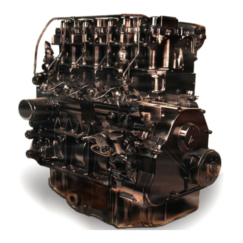
Hirth F-23 User manual

HIRTH OPERATOR’S MANUAL
F-23 engine
IMPORTANT: THIS MANUAL CONTAINS IMPORTANT
SAFETY AND MAINTENANCE INFORMATION CONCERNING
YOUR ENGINE. IT MUST BE READ THROUGH IN ITS
ENTIRETY AND COMPLIED WITH WHERE APPLICABLE
IMMEDIATELY UPON RECEIPT OF ENGINE, EVEN IF THE
ENGINE WILL NOT BE USED IMMEDIATELY. THIS MANUAL
MUST STAY WITH THE ENGINE AT THE TIME OF RESALE.
Hirth Motoren and related agents reserve the right to make changes, additions,
deletions, and supercessions to this manual without notice.

2
INDEX
Break-In Page 5
Gasoline and Oil Page 8
Engine checks Page 9
Starting procedure Page 10-11
Run up procedure Page 11-12
Engine Shutdown Page 13
Belt reduction drive Page 14
Gearbox/Recoil Starter Page 15
Fuel System Page 17-18
Carburetor Info Page 19
Problem solving Page 19-21
Wiring diagram Page 22
PVL Ignition Page 23
Free Air Cooling Page 24-25
Exhaust System Page 26
Torque Values Page 27
Engine Setting Values Page 27
Maintenance Schedule Page 28-30
Troubleshooting Page 31-33
Engine maintenance repair log Page 34

3
UPON RECEIVING THE ENGINE
Check external appearance of the box and note any damage, especially any holes caused by
penetration of a sharp object. When signing for a shipment, be sure to sign it off as “Subject
to Inspection”. In this manner, if there is any damage that was not obvious at the time of
delivery, you will usually have a couple of days to make a damage claim to the carrier.
Check that the engine and equipment, etc. have not sustained any damage. If damaged, make
written note. A photograph of the damage is desirable, not only of the damaged piece but
photos of the box and packaging.
Take care not to touch carburetor adjustments just yet. Carburetors are adjusted at the
factory to a point where the engine will start; yet not overspeed providing that an adequate
propeller is installed.
FORWARD
Congratulations on your purchase of a new Hirth engine! If properly installed and
maintained, you should receive many years of reliable service from the engine.
Description: The engine F-23 of Hirth Motoren GmbH & Co. KG is an air-cooled, Piston
port-controlled opposed two-cylinder 2-stroke-engine. The cylinder consists of an aluminium
alloy with wear-resistant tread alloy. Each cylinder is mounted to crankcase with 4 threaded
studs secured with hexagon head nuts. The cylinder head consists of a special aluminium
alloy that retains the same temper/ hardness in high temperatures. It is attached to cylinder-
by-cylinder screws and does not require a head gasket. The piston consists of an aluminium
alloy and is centered by two piston rings expanding against the cylinder wall. The piston is
attached to the connecting rod by piston pin and needle bearing. The crankshaft consists
Chrom-Molybdän-Steel (42 Cr Mo 4) and is mounted in 3 ball bearings. It conforms to what
is known as a manufactured or segmented crankshaft. The output drive is conical and
equipped with centric external thread for mounting a junction cone on output drive. The
connecting rod is connected with/linked to the crankshaft through a crankpin and a needle
bearing. The crankcase consists of an aluminium alloy. It is constructed as a divided case and
consists of ignition part and an output driving part. Four cylinder screws with locking ring
hold crankcase halves together. It picks up the stator plate of the ignition system on the side
of ignition. Hirth reserves the right to make modifications to their designs without notice.
This manual covers basic engine operations and maintenance. For items and accessories not
made by Hirth, refer to appropriate manufacturer’s service instructions.
When performing maintenance, always use genuine Hirth parts.

4
WARNING
This engine is not a certified aircraft engine. It does not conform to any aircraft standards
and it has not undergone safety or durability testing for any type of aircraft certification. It is
an experimental aircraft engine for use in experimental aircraft and should always be treated
as such. Occasionally, the experiment may have side affects, for example engine failure,
complete loss of power, etc.
This engine is an aircraft engine and should be treated as such. Even more than it being an
aircraft engine, it is an experimental aircraft engine, so even more precautions should be
taken than in the case of a certified aircraft engine, for example, constantly making sure that
all systems are functional, safe, thorough maintenance is completed, etc.
The user assumes all risk of use and acknowledges so by its use, that he/she knows this engine
can experience mechanical failure. Engine failure can result in crash landings that may lead
to injury and/or death.
Never operate the engine if there is any chance of causing damage to persons or properties.
Never operate the aircraft at locations, airspeeds, altitudes or other circumstances from
which, upon engine failure, a successful and uneventful no power landing cannot be made and
the user is proficient in making such landings.
Never operate the engine at any time, under any circumstances or in any manner, which will
compromise safety.
Passengers and/or any associated persons/parties are considered users.
It is the responsibility of the owner/operator to inform any passengers and/or associated
persons/parties of the above statements and responsibilities.

5
INTRODUCTION
As with any other fine piece of high performance machinery, the Hirth engine requires
proper maintenance and care. For instance, it is absolutely vital that proper, clean, fuel and
the correct oil pre-mixed be supplied to the engine. Further, the carburetors must be properly
tuned, made sure of no leaks, must be kept clean and in proper working order, etc.
The Hirth engine is, of course, a piece of machinery. As with any piece of machinery, parts
will eventually wear and/or fail. It is very important to do regular maintenance and
inspections on your engine, inspecting, adjusting, repairing and/or replacing the parts as
required. In which case, the risk of having an engine failure will be minimized.
This manual contains much information regarding your engine, however, it is by no means
complete nor tells every detail, as it is impossible to list every piece of information and effect
that each detail may or may not have in conjunction with all of the other related aspects. As
you can see, the possibilities are endless.
For information regarding a specific topic that may or may not be covered in this manual,
consult with your local Hirth technical representative.
This manual has been compiled from many sources of information, testing and experience.
Other than simple operating and maintenance information, it contains many helpful hints
and do’s and don’ts. Take each piece of information and give it proper attention no matter
how insignificant it may seem. Some points in this manual have been included due to someone
finding out the hard way. Don’t let that person’s painstaking experience be in vain. This
information is supplied to you in order to help keep you and your engine safe. It is a good idea
to read this manual completely more than once and to constantly refer to it as required.

6
BREAK IN
READ SECTION THOROUGHLY BEFORE PROCEEDING WITH BREAK IN.
It is recommended that the first hours of operation should only be performed with the help of
someone with good experience in the operation of two cycle engines mounted in experimental
aircraft. It would be further beneficial for this person to be knowledgeable in the area of
carburetor tuning for this type of engine.
Ensure that engine installation is complete and as per installation instructions.
Ensure that all systems are correct, functional, safe, etc.
Ensure that you have read and complied with all appropriate information. Further, that you
understand what you, as owner and/or operator are responsible for.
THE BREAK IN PROCEDURE MUST BE PERFORMED WITH THE ENGINE
PROPERLY INSTALLED AS PER INSTALLATION INSTRUCTIONS. FURTHER, THE
PROPELLER MUST BE INSTALLED AND PITCHED TO MAKE NEAR MAXIMUM
RATED RPM YET NOT ALLOW THE ENGINE TO OVERSPEED.
NOTE:
For free-air cooled engines, it is critical that proper steps be taken to ensure adequate cooling.
Refer to section in this manual regarding starting procedure.
Take care not to jerk the engine rpm up and down. Increase and decrease rpm smoothly. It
will eventually be necessary to increase RPM instantly as well as decrease instantly in order
to properly set carburetors, however, this type of carb tuning is best left until the engine has
been properly run in.
Make carburetor adjustments as necessary.
If at any time problems arise, shut down the engine, find the cause and rectify.
Take care not to let the engine idle for too long as an extended low power setting can cause
unnecessary carbon deposits.
In the first 10 hours of operation, run in the engine with due care. It should not be revved up
or overloaded unnecessarily.

7
…BREAK IN CONTINUED
During break in, carburetor setting should be completed. Max allowable CHT - 535 F. Max
allowable EGT –1256 F at full power. Max EGT in mid range –1330 F. Engines should be
jetted to run at approximately 100 to 150 degrees EGT below maximum
Run-in engine easily for the first two hours. Avoid full power in the first hour of operation.
When engine is first started find the best idle RPM. This is the lowest RPM the engine will
run smoothly at and will vary depending on application. If supplied with a clutch very low
idle Rpms are possible (800 to 1200 Rpm). When supplied with the belt drive idle speed will
be higher 1600 to 2200 Rpm. Heavy props require higher idle speeds than lighter props. Now
is the time to adjust the air screw (s) on the carburetor (s) and to get the idle stop screw (s)
set.
After your idle adjustments are complete advance Rpm to 2500 for 20 minutes. After 20
minutes return to idle speed until engine cools and then advance Rpm to 3000 for 20 minutes.
After 20 minutes at 3000 Rpm return to idle speed until engine cools and then advance Rpm
to 3500 for 20 minutes. After 20 minutes at 3500 return to idle for a cool down and then
advance to 4000 Rpm for 20 minutes. At the end of the 4000 Rpm run you will have 1 hour
and 20 minutes break in time on the engine. During each of these 20-minute runs you should
record the EGT and CHT for each run. If temperatures are out of range stop break in and
rectify cause.
After 20 minutes at 4000 return to idle speed for a cool down. Advance to full throttle for 3 to
4 seconds and then smoothly return to idle. This is to determine if your prop is pitched
correctly. If engine exceeds peak Hp Rpm (6150 Rpm) stop break in and add pitch. Restart,
warm up at idle and then go to full throttle again to check if your pitch adjustments now hold
the engine to peak RPM. If engine is more than 200 Rpm below peak Rpm prop pitch will
have to be reduced to allow engine to come up to proper speed. If engine is more than 100
Rpm above peak Rpm prop pitch will have to be increased to bring engine Rpm down to
proper speed. If your prop is not pitched correctly the EGT’s and CHT’s you record for the
2nd half of the break in will not be accurate. Also serious engine damage can occur when
running without enough load to keep engine at peak Hp Rpm.
After your prop adjustments are complete restart and warm up engine at idle. Advance Rpm
to 4500 for 20 minutes. After 20 minutes return to idle speed until engine cools and then
advance Rpm to 5000 for 20 minutes. After 20 minutes at 5000 Rpm return to idle speed until
engine cools and then advance Rpm to 5500 for 20 minutes. After 20 minutes at 5500 return
to idle for a cool down and then advance to full power for 2 minutes. If CHT exceeds
maximum (535 deg. F.) before the end of the 2-minute run reduce power to idle for a short
cool down and then complete the remainder of the 2-minute full power run. EGT should be
below 1150 at full power. During each of these 20-minute runs you should record the EGT
and CHT for each run. If temperatures are out of range stop break in and rectify cause.
After break in is complete allow engine to cool completely and then check the torque of the
head bolts, cylinder base nuts, intake manifold bolts and exhaust bolts. It will take several
hours for engine to completely cool down. Do not re-torque when engine is warm. If not
possible to re-torque after break in it is imperative that top end re-torque is done within the
1st. 10Hrs.

8
INSPECTIONS
Safety is top priority! If you keep your engine in top condition you will greatly reduce the
risk of having an engine failure. If you continually check all systems you will know your
engine much better and therefore be able to recognize any potential problems much easier.
Do not overlook a single point!
Check all points and aspects for wear, condition, operation, security, leaks and serviceability.
If anything is not absolutely in top condition or perfectly adjusted, do not operate engine until
those points are taken care of in order to bring them up to top standards.
The following is a guideline for you to follow. There will be additional points to check on a
regular basis such as accessories. Make notes of these additional points and add them to this
list.
Check each point and give it proper attention.
ADDITIONAL IMPORTANT POINTS
Always maintain an engine maintenance and repair log.
Always keep air filter clean and in good condition.
Always keep engine clean. Wash on a regular basis. If seepage occurs from around cylinders,
intake and exhaust area. #1 Repair leaks immediately. #2 Clean engine thoroughly.
Always ensure all maintenance and inspections have been completed.
Always ensure all systems are in top condition and serviceable.
Never operate engine before reading this manual thoroughly and conforming to it where
applicable.
Never operate engine without both ignition systems functioning.
Never engage starter mechanism without at least one spark plug for each ignition circuit
installed with the spark plug terminal in place unless ignition circuits are shut off.
Never operate engine beyond maximum rated engine RPM.
Never add oil directly into fuel tank, and then simply pour gas into tank. They may not mix
adequately.
Never add fuel while engine is running.
Never add fuel if there is any chance of spilling on hot engine parts.
Never pour unfiltered fuel into fuel tank.
Never use fuel or gasoline more than one month old.
Never store fuel or gasoline in a warm area.
Never store fuel or gasoline where it is exposed to sunlight.
Never use fuel or gasoline that contain harmful additives.
Never us fuel that contains water.
Never run engine without propeller or proper load bearing device.
Never operate engine without engine-monitoring gauges required, (EGT, CHT, &
Tachometer) properly installed and functional.
Never operate engine in any manner that will compromise safety.

9
GASOLINE AND OIL
Contaminated fuel is a major cause of engine failure. Before you introduce fuel into the fuel
system, be sure to take precautions to see if your fuel is contaminated. Check for water, dirt,
crud and other undesirable substances.
GASOLINE
Use Premium unleaded auto gas. If possible avoid using gas that has ethanol or methanol
mixed with it. Aviation 100 LL can be used occasionally but will decrease spark plug and
piston ring life substantially. The lead in 100LL sticks to engine parts the same as carbon
deposits.
OIL
50:1 Ratio oils: Use a high quality name brand two cycle engine oil for air cooled engines with
corrosion inhibitor, preferably with a low ash content. If fuel injected mix at 45:1
100:1 Ratio oils: Blue Max is the only 100:1 oil that has been tested and approved by Hirth. If
you elect to use Blue Max it should be mixed at 90:l. Do not use Blue Max at ratios lower than
90:1. There will be too many lubricants introduced into the system and they may not all burn
off. In which case, piston rings may stick in only a few hours. Do not use Blue Max pre mix oil
in engines equipped with oil injection. For oil injected engines use Blue Max injection oil.
NOTE: If engine is fuel injected, mix Blue Max at 90:1 –1.42oz of oil per gallon of gas.
FUEL MIXTURE
In this manual, gasoline and oil mixed together are referred to as fuel.
Gasoline/oil mix ration of 2%. (50:1) | Gasoline/oil mix ration of 1%. (100:1)
1 unit of oil to 50 units of gasoline. | 1 unit of oil to 100 units of gasoline.
200 ml of oil to 10 liters of gasoline. | 100 ml of oil to 10 liters of gasoline.
12.8 fl oz of oil to 5 gallons of gasoline | 6.4 fl oz of oil to 5 gallons of gasoline
Oil Mixing formula 50:1: 2.56, X gallons being mixed. Example-5 gallons at 50:1 - 2.56, X 5
gallons = 12.8 oz. of oil. / 6 gallons at 50:1 –2.56 X 6 gallons = 15.36 oz.
Oil Mixing formula 100:1: 1.28, X gallons being mixed. Example-5 gallons at 100:1- 1.28, X
5 gallons = 6.4 oz. of oil. / 6 gallons at 100:1 –1.28 X 6 gallons = 7.68 oz.
MIXING PROCEDURE:
1. Always premix oil and gasoline.
2. Use an approved container of known volume.
3. Ensure container is clean.
4. Add 1 gallon of gasoline.
5. Add pre measured (By above formulas) 2 cycle oil.
6. Shake container vigorously.
7. Add remaining gasoline required to fill container.
8. Shake container again lightly to complete the fuel mix.
Ground aircraft or vehicle to fuel dispenser with a grounding wire when required. Filter fuel
through a fine mesh screen before it enters the tank.
If equipped with optional oil injection refer to oil injection manual for lubrication
information.
#1 CHECK. (TO BE PERFORMED BEFORE EVERY FLIGHT)

10
Check that the ignition switch is off.
Check carburetor rubber flange for cracks, signs of wear, etc.
Check carb for secure attachment.
Check carburetors for proper tuning and adjustment, as required for climatic changes such
as temperature, pressure, field altitude, etc.
Drain a small quantity of fuel from fuel tank(s) sump. Remove any accumulated water and
dirt.
Check carb float-bowl for water, dirt, sediment, etc. Drain.
Check condition, security and cleanliness of air filter.
Check fuel system to be free of leaks and seepage. Check for security and condition.
Check fuel filter.
Check engine for fuel and/or air leaks. Example: Around intake system, cylinder base,
cylinder heads, exhaust manifold, etc.
Check all ignition wires for condition, security, and proper function.
Check all engine wires for condition, security, and proper function.
Check ignition-mounting points for wear, secure attachment, condition, etc.
Check engine mount & mounting parts for security, cracks, condition, etc.
Check operation and stops of controls such as throttle, choke, etc. Further, check for secure
attachment, condition and smooth action.
Rotate engine by hand on propeller. Listen and feel for unusual occurrences. It is wise to
remove the spark plug caps or some other positive way to ensure that the engine will not fire.
Check propeller for secure attachment, and condition (nicks, cracks, crud, etc.)
Check spark plug caps for security, condition.
Check exhaust system for security, condition, cracks, wear, broken springs, etc.
Check gearbox for oil leaks (if equipped)
Check belt reduction for serviceability, adjustment, condition of belt, etc. (if equipped)
Check propeller shafts bearings for damage and/or play by rocking propeller.
Check all systems functional and top condition.
Check that all fasteners are tight.
Check fan belt for tension, wear, inversion, and blockages, etc if equipped with fan cooling.
Check that items such as animals, insects, sand, ice, snow, or other foreign matter have not
become lodged in the engine area.
Check engine, reduction unit and all other ancillary components for loose or missing nuts,
bolts and other fasteners, parts and pieces.
Check all other points for condition, operation, security, leaks, condition and serviceability,
etc. necessary.
Check that fuel level is adequate for proposed operation.
Check accessories and other ancillary equipment for security, condition, operation,
adjustment, serviceability, etc. as appropriate.
Complete pre-start check.
Complete run-up procedure.

11
PREPARING TO START ENGINE FOR THE FIRST TIME
Read the Operating and Maintenance instructions completely and comply where applicable.
Ensure that the installation is complete.
Ensure that all systems are ready and functional.
Make sure that the operator has spent some time getting acquainted with the cockpit and can
properly operate the engine controls by instinctive reaction. Further, that the operator is
familiar with engine temperature gauges and knows the maximum limits.
Move aircraft to a safe run-up area.
Secure the aircraft to prevent movement during run-up.
Warn anyone who is in the vicinity to keep clear of the propeller.
Proceed to Pre-start Check in the manual.
PRE-START CHECK
Before starting engine for the first time, read section titled Starting engine for the first time.
Do a complete daily inspection (#1 check)
Make sure that all required maintenance and inspections have been completed.
Ensure that the area is safe and aircraft secure.
Note any changes in temperature and barometric pressure since last operation. Changes may
indicate a need for re-tuning of carburetors. Keep these changes in mind while completing
run-up procedure and watching engine temperatures.
STARTING PROCEDURE
STARTING A COLD ENGINE.
1. Fuel on.
2. Master switch on. (if installed)
3. Set throttle to idle position.
4. Choke or enricher on.
5. Call out “all clear”. A person in the vicinity should call back “wait” or “all clear” as
appropriate.
6. Both Ignition switches on.
7a. Engage starter switch or button. Remember not to engage for more than 5-7 seconds. See
section dealing with electrical starter for complete instructions.
7b. Make use of the recoil starter. See section dealing with recoil starter for complete
instructions.
8. When engine starts, increase the throttle setting slightly and slowly shut off choke or
enricher.
10. Once choke or enricher has been shut off, let engine run at that position for ten to fifteen
seconds, unless engine is running rough at this setting. If so, move throttle to find smoother
running position.

12
11. Increase throttle setting to increase engine RPM to approximately 2500 RPM. Allow
engine to run for a few minutes at this setting.
12. Maneuver to a proper run-up area and complete engine run-up. Refer to Run-up
Procedure.
Note: If engine will not start after 3-4 attempts, check the spark plugs.
Refer to section dealing with Trouble-Shooting.
STARTING A HOT ENGINE:
1. Fuel on.
2. Master switch on. (if installed.)
3. Throttle setting to 10%-20% position.
4. Choke or enricher off.
5. Call out “all clear”. A person in the vicinity should call back “all clear” or “wait,” as
appropriate.
6. Ignition switches on.
7a. Engage starter switch or button. Remember not to engage for more than 5-7 seconds. See
section dealing with electrical starter for complete instructions.
7b. Make use of the recoil starter. See section dealing with recoil for complete instructions.
8. When engine starts, immediately move throttle setting to idle.
9. Let run at low speed for a couple of minutes.
10. Maneuver to a proper run-up area and complete engine run-up. Refer to Run-up
Procedure.
Note: If engine does not start after 3-4 attempts, apply a little more throttle. If engine still will
not start, check the spark plugs. Refer to section dealing with Trouble Shooting.
RUN-UP PROCEDURE PART #1
Never operate engine without propeller or other RPM restricting device.
After 2 or more minutes at 1800-2500 RPM, open throttle to 3000-4000 RPM for three to four
minutes and observe:
A. No strange or unusual noises.
B. Cylinder head temperature is in range and well below maximum.
C. Exhaust temperature is within range and below maximum.
D. Check for smooth running and then return to idle Rpm.
E. Turn off 1st ignition switch, check smooth drop of 50-100 RPM. Turn switch back on.
Turn off 2nd ignition switch. Check for smooth drop of 50-200 RPM. Turn switch back on.
Only do mag checks at idle Rpm and only for 1 second each.
F. Checks for other equipment if installed.
NOTE: These portions of the run-up #1 and #2 are also used as a warm up of the engine and
is not to be hurried. If engine is equipped with fuel injection refer to fuel injection manual for
cold and hot starting procedures.

13
RUN UP PROCEDURE PART “2”
Upon completion of Run-up #1, move the throttle setting to maximum and observe:
a. Maximum static RPM to be approximately 85% -95% of 100% BHP.
b. Cylinder head temperature is in range. See temperature chart.
c. Exhaust gas temperature is in range.
NOTE: Do not operate engine above maximum engine RPM. See technical data page
regarding your engine.
RUN UP PROCEDURE PART “3”
Upon completion of Run-up procedure, part 2, move the throttle setting to idle and observe:
a. Idle speed is as per required, depending on equipment installed. (usually 1800-2200 RPM)
b. other instruments read normal.
IN FLIGHT
Take off and climb at full throttle.
Remember to ensure that engine temperatures never exceed maximum.
Upon reaching circuit or cruise altitude, set throttle back to cruise power. This RPM is
determined by the speed requirements of the aircraft, and/or pilot preference.
NOTES: Ensure never to operate engine above maximum engine RPM.
Take care not to operate the engine at a lower throttle setting yet producing a higher RPM.
For example, in a dive. This can lean the fuel mixture and increase engine temperatures to a
critical level that may cause damage to the engine and/or engine failure.
If there is a throttle setting that produces the same RPM as a setting in the more open
position, use the setting that is of the more open position. This will help ensure cooler engine
temperatures.
Engine Shutdown
1. Set engine RPM to idle speed for a short cool down period.
2. Complete an ignition check, (mag check) as described in Run-up section #1E.
3. Ignition switches off. If equipped with fuel injection turn injection power off first. When
engine comes to a complete stop turn ignition switches off.

14
STARTING DEVICES
Starting with electric starter
Operate starter switch or starter button. Do not engage for more than 5 seconds. If it doesn’t
start within that time, let it cool before another attempt is made.
Starting with recoil Starter
Hold the handle of the recoil starter with one hand. Brace the engine (or appropriate) with
the other hand. Pull out the handle gently until resistance is felt. Now pull vigorously and
swiftly about one arm length. Let the handle slowly back until all of the cable has reverted
back into the starter housing.
In order to avoid damage to the starter as well as several other possible problems, do not
return handle abruptly or let go of the handle altogether until the cable has returned itself
completely into the housing. Repeat if necessary.
GROOVED BELT REDUCTION DRIVE
ADJUSTING PROCEDURE
Loosen locking bolt slightly. This is an M-10 bolt, which lies perpendicular to the line of the
crankshaft.
Turn the propeller shaft to remove tension from the belt. This should be in a clockwise
direction as viewed toward the PTO.
Take note of direction of belt, remove belt and inspect.
Check bearings for unusual occurrences such as rough rotation. Rock the pulley back and
forth checking for excessive movement in the bearings.
Reinstall belt to turn the same direction as before. Ensure that it is on all the way and all
grooves fit together properly.
Tighten the belt counter-clockwise just to the point that the slack is taken up but yet the belt
is not stretched.
Measure the circumference of the belt.
Adjust the locking bolt to the point where it has some tension, however, you are still able to
turn the propeller shaft with only slight force.
Put a straightedge to the pulleys and adjust the large pulley fore and aft until the grooves are
paralleled and exactly match to the drive pulley.
Rotate the propeller shaft counter-clockwise stretching the belt.
Rotate the large pulley several revolutions.

15
Measure the belt. It is necessary to stretch the belt 1 millimeter for every 200 millimeters of
belt length.
Recheck belt length and alignment.
Repeat procedure if necessary.
Tighten locking bolt.
Recheck with straightedge. Realign and readjust if necessary.
GEARBOX
Regardless if the gearbox is installed on the engine or not, there is NO OIL in the gearbox.
Use 85/90 W gear oil.
Fill to lower oil level plug (sight glass) on the prop flange side of the gearbox. If gearbox is
inverted the sight glass should be moved to the lower position.
Drain upon completion of initial 2-hour break-in period.
Refill oil to proper level.
See Table of Torque Values for proper torquing.
Replace oil at 12.5 hours total time.
Replace oil at 50 hours of total time.
Replace oil every 50 hours of operation or 1 year whichever comes first.
Remove gearbox and inspect elastomeric dampener or centrifugal clutch, (as equipped) every
100 hours.
RECOIL STARTER
When recoil starter is removed, apply a small amount of grease to the annular spring which
hold the clamp rollers in place.
When recoil starter is to be installed it is necessary to install it by the following procedure;
insert the three M6 Allen screws but only tighten until snug.
Make sure that the ignition is “off,” and the engine cannot fire.
Make sure that the recoil starter can still be moved in a rotating motion.
Temporarily restrict the engine crankshaft from movement.
Pull on the starter handle. You will notice that the starter has centered itself.
With tension still on the starter handle, tighten the three M6 Allen screws.
Release handle.
Remove crankshaft restricting device.
Pull through a few times and ensure a smooth rewind.
More in-depth servicing of the recoil starter is best left to a Hirth Service mechanic.

16
INSTRUMENTATION
There are many engine monitoring instruments available for your Hirth engine. Of course, it
is good if you can have all of them available to you. However, weight and/or space limitations
may not allow all of them. The following instruments are minimally required to properly
operate the engine:
Tachometer
Cylinder Head Temperature (CHT) Monitor for each cylinder.
Exhaust Gas Temperature (EGT) Monitor for each cylinder.
NOTE: Use 10mm CHT sensors. Do not use 14mm CHT sensors. If using Westberg brand
EGT gauge combined with EIS brand EGT exhaust probes there must be 4 feet of
thermocouple extension wire spliced in to allow correct resistance to the probe and accurate
readings.
Installation of EGT thermocouple to be mounted 75mm. as measured through the center of
the exhaust tube, from the outer edge of the exhaust port. If using EIS EGT probes with
Westberg EGT gauge 4 feet of EGT extension wire must be spliced in to achieve proper
readings.
CARBURETORS
CARBURETOR ICE
WARNING!!! Carburetors can be susceptible to what is known as “Carb Ice.”
Carb ice can accumulate in the carburetor(s), which can seriously affect mixture, throttle
control and of course, performance. Carb ice, when encountered is usually serious and in the
worst conditions will cause engine stoppage.
It is the responsibility of the owner/operator to ensure that all precautions have been taken to
minimize the risk of carb ice, such as installing some sort of carburetor heating method which
will either prevent carb ice from forming or eliminate the ice before it becomes detrimental, if
ice does occur.

17
Note: 1 inch = 25.4 millimeters.

18
FUEL SYSTEM NOTES
When mounting fuel pump, mount it slightly above engine impulse nipple, in order that any
residual oil will drain back into the engine.
When mounting fuel pump, do not mount it solid to the engine, but rather, mount it on a
bracket which is attached to the airframe or part of the engine mount beyond the rubber
dampener on the airframe side, to avoid vibrations. If it is not possible to mount fuel pump to
air frame and attaching to the engine is the only alternative use vibration isolators.
If the aircraft will ever experience “G” forces during maneuvers, it may be necessary to
install an additional electric fuel pump in order to ensure constant fuel supply to the
carburetors, especially if the fuel lift height and hose lengths are near maximum
specifications.
Use fuel lines which are approved for the type of fuel which will be used.
Use fuel lines which have no chance of cracking or chafing.
Use hose clamps at hose connections.
Do not use soft hose for the pulse line. It can lower the delivered pulse pressure/vacuum to the
fuel pump, which can in turn lower the pumps capacity. Use stiff 14” ID hose for the pulse
line.
Ensure that the fuel tank as well as all other fuel system components are situated/located in
such a way that they will not cause a hazard near exhaust components or other places which
may have potential to cause ignition of spilled fuel.
Fuel lines should be routed in such a way that it is a constant slight incline or decline without
dips or humps. The lowest point of the fuel system should have some sort of draining device
which is able to drain the fuel system completely. In some cases this may be the carburetor
bowl.
Fuel lines should be secured at certain points in order that they will not rub against other
pieces.
Ensure that the fuel system is protected from heat sources.

19
CARBURETOR SETTING
With a pencil and pad, note type of carburetor and carb adjustment settings.
Refer to table of data and adjustments. These settings should be within ½turn from that
which is shown in table.
Note: The carburetor jets shown in chart of data and adjustments shows what jets come as
standard equipment with the engine and which would be a good starting point for
adjustments and settings in most cases. In no way does this chart show what would be
optimum carburetor jetting or settings for the users particular operating conditions at locale.
It is the responsibility of the owner/operator to ensure that the carburetors are jetted and
adjusted properly.
It is possible that the engine will require carburetor jets that are other than those which are
supplied. It is a good idea to purchase an assortment of carburetor jets.
In most cases, the supplied jets should be sufficient to optimally tune the engine for summer
and winter operation and sea level to several thousand feet field elevation.
Although jet changes may be required, these changes should not be conducted unless proper
Hirth tuning information is on hand and the changes are made by a qualified person.
Hirth uses different brands of carburetors throughout its engine line.
For engine model F-23 the Mikuni VM34mm slide-type float carburetor is standard.
Optionally available are the Mikuni Super BN 34mm carbs. Jetting varies between engine
models and standard factory jetting for each model is listed on the engine settings page in this
manual.
A Mikuni carburetor manual is included with engine. You should read it before running
engine and become familiar with how your carburetor operates and its different components.
If your engine was supplied with fuel injection, you should have received a fuel injection
operator’s manual. Refer to the fuel injection manual for all aspects of installation and
operation of the fuel system.

20
PROBLEM POSSIBLE CAUSE CORRECTION
HARD STARTING
Incorrect use of choke Correct use of choke
Incorrect air/fuel mixture adjustment Set adjustment screw
Incorrect use of throttle setting. See table of data and
adjustments
Restricted fuel filter Replace filter
Restricted low speed jet(s) Disassemble carb
and clean
Restricted vent hole in fuel cap Repair or replace
vent or cap
Float stuck Remove float(s)
check operation.
Rectify problem.
Float damaged or leaking Replace
Incorrect float level Adjust within specs
Intake air leak Check carb rubber
flange for cracks.
Check sealing points
for leaks.
Ignition problem. Repair, replace,
adjust as necessary.
Incorrect spark plug gap. Replace &/or adjust
as per specs.
Low cylinder compression Repair, replace, or
adjust as necessary.
Fuel line blocked Replace fuel line.
Fuel pump unserviceable Repair or replace
Fuel tank empty Fill tank with fuel
Leak or blockage in impulse line
between crankcase and fuel pump Replace line
Engine flooded Remove spark
plugs, dry or
renew the plugs
full throttle,
ignition off,
choke off, turn
engine over a
few times.
Return to normal
position and
settings
Dirty air cleaner Clean or replace
Water in fuel Drain fuel system
POOR IDLE OR STALLING
Idle speed adjustment(s) set too low Adjust idle rpm
Idle speed adjustment(s) are unequal
(twin carb models) Equalize throttle
stop settings
Clogged idle jet or air screw Disassemble carb
and clean
Table of contents
Other Hirth Engine manuals
Popular Engine manuals by other brands
V2
V2 LEX-KNX installation manual

FNM
FNM HPEP 225 installation manual
Kohler
Kohler KD15 440 Use & maintenance
Anhui Chery Automobile
Anhui Chery Automobile CAC478 Instruction Book on Using and Maintenance

Siemens
Siemens SIMOTICS DC 1GH6 operating instructions
Polini
Polini THOR 303 Use and maintenance manual
