Fireye SB Series User manual

1
The Fireye SBSeries Flame Safeguard Control is a compact, microprocessor based, modular
burner management system designed to provide automatic ignition and continuous flame
monitoring for com-mercial sizes of heating and process equipment firing any type of fuel.
The SBSeries are tested to EN298.
The control unit includes all the necessary digital logic and analog measuring circuitry to control
the sequence and monitor the flame of single gas, oil or combination gas/oil burners. Three
available control sequences are no-purge, purge, and modulation (air damper control). The part
number specifies the various features such as the flame sensor type, no purge, purge, modulation,
proof of air opening at start, and timings; thus the designer has control and protection against field
tampering of critical sequences.
LED indicators are available on the front of the unit that provide current operating status of the
burner system including lockout alarm. A test jack is recessed into the front cover that provides
real time reading of the connected flame sensor. This same test jack is also used to connect to an
alpha-numeric display, SB20896. A push button provides reset from lockout condition as well as
placing the unit in a check condition usable for pilot turn down test.
The SBSeries flame safeguard control family are of plug-in design and available in models that
operate at 120 VAC, 50/60 Hz and 230 VAC, 50/60 Hz making them universally acceptable.
*The wiring base provides a convenient means for connecting field wiring from the burner and
valve system to the control unit. There are three styles of bases: an internal terminal base that
provides a guarded wiring compartment; an external terminal base for use within a protective
control panel; and an expanded external terminal base for use with the modulation sequence
control units.
Sensors that may be used with the SBSeries include flame rod (rectified ionization), ultra-violet
(UV) scanners, and self-checking UV scanners for continuous operation. Four types of non self-
checking UV scanners meet the demands of various environmental conditions.
WARNING: Selection of this control for a particular application should be made by a
competent professional, licensed by a state or other government. Inappropriate application
of this product could result in an unsafe condition hazardous to life and property.
SB-2501
April 3, 2019
FIREYE®

2
Maximum
Minimum
Weight
SBSeries
140°F
60°C
-40°F
-40°C
3 lbs (1.4kg)
UV Scanner, straight; SB49600-91
257°F
125°C
-4° F
-20° C
1 lb (.45kg)
UV Scanner, 90 degree; SB49600-91
140°F
60°C
-4° F
-20° C
1 lb (.45kg)
UV Scanner, sealed, NEMA4, SB20898
257°F
125°C
-4° F
-20° C
1 lb (.45kg)
UV Scanner, self-check; SB49602-91
140°F
60°C
-4° F
-20° C
7 lbs (3.2kg)
Flame Rod (Tip 2460 F); 69ND1-1000K4,
-1000K6, -1000K8
1500°F
616°C
-40°F
-40°C
1 lb (.45kg)
Remote Display, 120 VAC; SB20896
22°F
50°F
32°F
0°C
1 lb (.45kg)
Function
Terminal
Inductive Load
The maximum total connected load
cannot exceed 15 Amps.
Gas Valves
3, 5
175 VA
Ignition
4
375 VA
Motor or Contactor
8
470 VA
Control
A, 10, 11, 12, 13
175 VA
WARNING: This equipment generates and can radiate radio frequency energy, and if not
installed and used in accordance with the instruction manual may cause interference to
radio communications. It has been tested and found to comply with the limits for a Class A
computing device pursuant to Subpart J of part 15 of FCC Rules, which are designed to
provide reasonable protection against such interference when operated in a commercial
environment. Operation of this equipment in a residential area is likely to cause
interference
SBSeries SPECIFICATIONS
Power Supply:
120VAC (min. 102, max 132) 50/60 Hz.
230 VAC (min 196, max 253) 50/60 Hz.
Power Consumption: 12VA (internal consumption, excludes externally connected loads)
Shipping Weight (Approx): 3 lbs (1.4 kg)
AMBIENT TEMPERATURE LIMITS
LOAD RATINGS
CAUTION: Published load ratings assume that no control be required to handle inrush
current more often than once in 15 seconds. The use of control switches, solenoids, relays,
etc. which chatter will lead to premature failure. It is important to run through a test
operation (with fuel shut off) following the tripping of a circuit breaker, a blown fuse, or
any instance of chattering of any external current consuming devices.
WARNING: Selection of programmer and amplifier type for a particular application should
be made by a competent professional, such as a Boiler/Burner technician licensed by a state or
government agency, engineering personnel of the burner, boiler or furnace manufacturer
(OEM) or in the performance of duties based on the information fromthe OEM.
3
Eclipse Part Number
Fireye Part Number
Description
VF560222AA
SB560222AA
120VAC, 5/10TFI, UV,PURGE
VF560222AB
SB560222AB
120VAC, 5/10TFI, UV,PURGE
VF560222XA
SB560222XA
120VAC, 5/10TFI, UV,PURGE
VF560222XB
SB560222XB
120VAC, 5/10TFI, UV,PURGE
VF560223AA
SB560223AA
120VAC, 5/10TFI, FR,PURGE
VF560223AB
SB560223AB
120VAC, 5/10TFI, FR,PURGE
VF560223XA
SB560223XA
120VAC, 5/10TFI, FR,PURGE
VF560223XB
SB560223XB
120VAC, 5/10TFI, FR,PURGE
VF560227AA
SB560227AA
120VAC, 5/10TFI, IR,PURGE
VF560227AB
SB560227AB
120VAC, 5/10TFI, IR,PURGE
VF560227XA
SB560227XA
120VAC, 5/10TFI, IR,PURGE
VF560227XB
SB560227XB
120VAC, 5/10TFI, IR,PURGE
VF560232AA
SB560232AA
120VAC, 5/10TFI, UV, NO PURGE
VF560232AB
SB560232AB
120VAC, 5/10TFI, UV, NO PURGE
VF560232XA
SB560232XA
120VAC, 5/10TFI, UV, NO PURGE
VF560232XB
SB560232XB
120VAC, 5/10TFI, UV, NO PURGE
VF560233AA
SB560233AA
120VAC, 5/10TFI, FR,NO PURGE
VF560233AB
SB560233AB
120VAC, 5/10TFI, FR,NO PURGE
VF560233XA
SB560233XA
120VAC, 5/10TFI, FR,NO PURGE
VF560233XB
SB560233XB
120VAC, 5/10TFI, FR,NO PURGE
VF560237AA
SB560237AA
120VAC, 5/10TFI, IR, NO PURGE
VF560237AB
SB560237AB
120VAC, 5/10TFI, IR, NO PURGE
VF560237XA
SB560237XA
120VAC, 5/10TFI, IR, NO PURGE
VF560237XB
SB560237XB
120VAC, 5/10TFI, IR, NO PURGE
VF560242AA
SB560242AA
120VAC, 5/10TFI, UV, MODULATION
VF560242AB
SB560242AB
120VAC, 5/10TFI, UV, MODULATION
VF560242XA
SB560242XA
120VAC, 5/10TFI, UV, MODULATION
VF560242XB
SB560242XB
120VAC, 5/10TFI, UV, MODULATION
VF560243AA
SB560243AA
120VAC, 5/10TFI, FR, MODULATION
VF560243AB
SB560243AB
120VAC, 5/10TFI, FR, MODULATION
VF560243XA
SB560243XA
120VAC, 5/10TFI, FR, MODULATION
VF560243XB
SB560243XB
120VAC, 5/10TFI, FR, MODULATION
VF560247AA
SB560247AA
120VAC, 5/10TFI, IR, MODULATION
VF560247AB
SB560247AB
120VAC, 5/10TFI, IR, MODULATION
VF560247XA
SB560247XA
120VAC, 5/10TFI, IR, MODULATION
VF560247XB
SB560247XB
120VAC, 5/10TFI, IR, MODULATION
VF560322AA
SB560322AA
240VAC,5/10TFI,UV,PURGE
VF560322AB
SB560322AB
240VAC,5/10TFI,UV,PURGE
Flame Safeguard Controls
4
Eclipse Part Number
Fireye Part Number
Description
VF560322XA
SB560322XA
240VAC, 5/10TFI, UV, PURGE
VF560322XB
SB560322XB
240VAC, 5/10TFI, UV, PURGE
VF560323AA
SB560323AA
240VAC, 5/10TFI, FR, PURGE
VF 560323 AB
SB560323AB
240VAC, 5/10TFI, FR, PURGE
VF560323XA
SB560323XA
240VAC, 5/10TFI, FR, PURGE
VF560323XB
SB560323XB
240VAC, 5/10TFI, FR, PURGE
VF560327AA
SB560327AA
240VAC, 5/10TFI, IR, PURGE
VF 560327 AB
SB560327AB
240VAC, 5/10TFI, IR, PURGE
VF560327XA
SB560327XA
240VAC, 5/10TFI, IR, PURGE
VF560327XB
SB560327XB
240VAC, 5/10TFI, IR, PURGE
VF560332AA
SB560332AA
240VAC, 5/10TFI, UV, NO PURGE
VF 560332 AB
SB560332AB
240VAC, 5/10TFI, UV, NO PURGE
VF560332XA
SB560332XA
240VAC, 5/10TFI, UV, NO PURGE
VF560332XB
SB560332XB
240VAC, 5/10TFI, UV, NO PURGE
VF560333AA
SB560333AA
240VAC, 5/10TFI, FR, NO PURGE
VF 560333 AB
SB560333AB
240VAC, 5/10TFI, FR, NO PURGE
VF560333XA
SB560333XA
240VAC, 5/10TFI, FR, NO PURGE
VF560333XB
SB560333XB
240VAC, 5/10TFI, FR, NO PURGE
VF560337AA
SB560337AA
240VAC, 5/10TFI, IR, NO PURGE
VF 560337 AB
SB560337AB
240VAC, 5/10TFI, IR, NO PURGE
VF560337XA
SB560337XA
240VAC, 5/10TFI, IR, NO PURGE
VF560337XB
SB560337XB
240VAC, 5/10TFI, IR, NO PURGE
VF560342AA
SB560342AA
240VAC, 5/10TFI, UV, MODULATION
VF 560342 AB
SB560342AB
240VAC,5/10TFI, UV, MODULATION
VF560342XA
SB560342XA
240VAC, 5/10TFI, UV, MODULATION
VF560342XB
SB560342XB
240VAC, 5/10TFI, UV, MODULATION
VF560343AA
SB560343AA
240VAC, 5/10TFI, FR, MODULATION
VF 560343 AB
SB560343AB
240VAC, 5/10TFI, FR, MODULATION
VF560343XA
SB560343XA
240VAC, 5/10TFI, FR, MODULATION
VF560343XB
SB560343XB
240VAC, 5/10TFI, FR, MODULATION
VF560347AA
SB560347AA
240VAC, 5/10TFI, IR, MODULATION
VF 560347 AB
SB560347AB
240VAC, 5/10TFI, IR, MODULATION
VF560347XA
SB560347XA
240VAC, 5/10TFI, IR, MODULATION
VF560347XB
SB560347XB
240VAC, 5/10TFI, IR, MODULATION
VF560522AA
SB560522AA
120VAC,10/15TFI, UV, PURGE
Flame Safeguard Controls

5
Eclipse Part Number
Fireye Part Number
Description
VF560522AB
SB560522AB
120VAC, 10/15TFI, UV, PURGE
VF560522XA
SB560522XA
120VAC, 10/15TFI, UV, PURGE
VF560522XB
SB560522XB
120VAC, 10/15TFI, UV, PURGE
VF560523AA
SB560523AA
120VAC, 10/15TFI, FR, PURGE
VF560523AB
SB560523AB
120VAC, 10/15TFI, FR, PURGE
VF560523XA
SB560523XA
120VAC, 10/15TFI, FR, PURGE
VF560523XB
SB560523XB
120VAC, 10/15TFI, FR, PURGE
VF560527AA
SB560527AA
120VAC, 10/15TFI, IR, PURGE
VF560527AB
SB560527AB
120VAC, 10/15TFI, IR, PURGE
VF560527XA
SB560527XA
120VAC, 10/15TFI, IR, PURGE
VF560527XB
SB560527XB
120VAC, 10/15TFI, IR, PURGE
VF560532AA
SB560532AA
120VAC, 10/15TFI, UV, NO PURGE
VF560532AB
SB560532AB
120VAC, 10/15TFI, UV, NO PURGE
VF560532XA
SB560532XA
120VAC, 10/15TFI, UV, NO PURGE
VF560532XB
SB560532XB
120VAC, 10/15TFI, UV, NO PURGE
VF560533AA
SB560533AA
120VAC, 5/10TFI, FR, NO PURGE
VF560533AB
SB560533AB
120VAC, 10/15TFI, FR, NO PURGE
VF560533XA
SB560533XA
120VAC, 10/15TFI, FR, NO PURGE
VF560533XB
SB560533XB
120VAC, 10/15TFI, FR, NO PURGE
VF560537AA
SB560537AA
120VAC, 10/15TFI, IR, NO PURGE
VF560537AB
SB560537AB
120VAC, 10/15TFI, IR, NO PURGE
VF560537XA
SB560537XA
120VAC, 10/15TFI, IR, NO PURGE
VF560537XB
SB560537XB
120VAC, 10/15TFI, IR, NO PURGE
Eclipse Part Number
Fireye Part Number
Description
20898
SB20898
NEMA 4 UV SCANNER (ECLIPSE)
49600-90
SB49600-90
90 DEGREE UV SCANNER
49600-91
SB49600-91
STRAIGHT UV SCANNER (ECLIPSE)
49600-98
SB49600-98
MAGNIFYING LENS ASSY (ECLIPSE)
49602-91
SB49602-91
SELF-CHECK SCANNER (ECLIPSE)
49600-98
SB49600-98
MAGNIFYING LENS ASSY (ECLIPSE)
49099
SB49099
COUPLING INSUL, 1/2" FNPT
Flame Safeguard Controls
Flame Scanners and Accessories

6
Eclipse Part Number
Fireye Part Number
Description
22194
SB22194
INTERNAL TERMINAL BASE, PL
22195
SB22195
WIRING BASE, PLASTIC, EXPO
49602-40
SB49602-40
MODULATION BASE (ECLIPSE)
Eclipse Part Number
Fireye Part Number
Description
20896
SB20896
REMOTE DISPLAY, 120V W/KEYPAD
20318
SB20318
CABLE FOR REMOTE DISPLAY
Wiring Bases
Displays
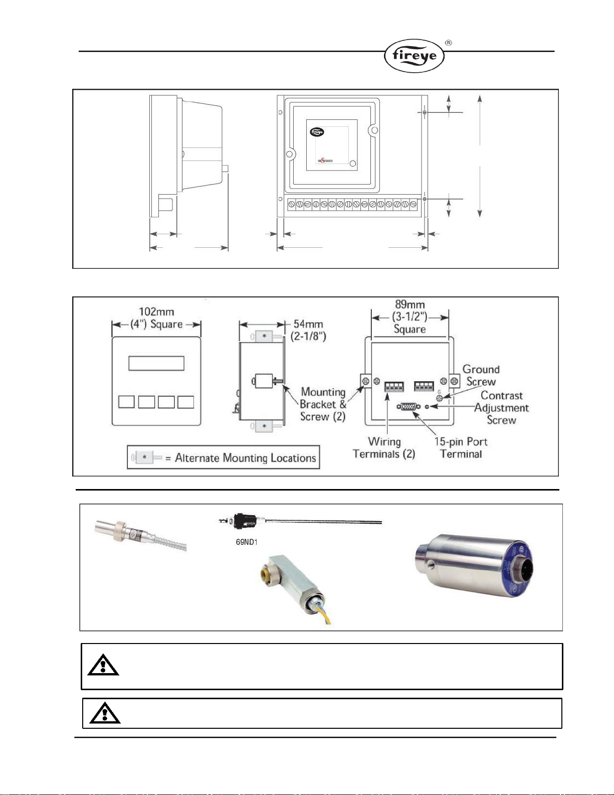
DIMENSIONS
FIGURE 1 SBSeries Control Unit, all models
FIREYE Inc
(76mm)
3"
5-1/4" Square
(133mm)
FIGURE 2 SBSeries Bases, NO PURGE and PURGE sequence models
7
FIGURE 4 Remote Display SB20896
FIGURE 3 SBSeries MODULATION sequence model, SB49602-40
116mm
4-9/16"
(40mm)
1-9/16"
3/8" (10mm) 3/16" (5mm)
8-3/8" (213mm)
(25mm)
(24mm)
15/16"
1"
(171mm)
6-3/4"
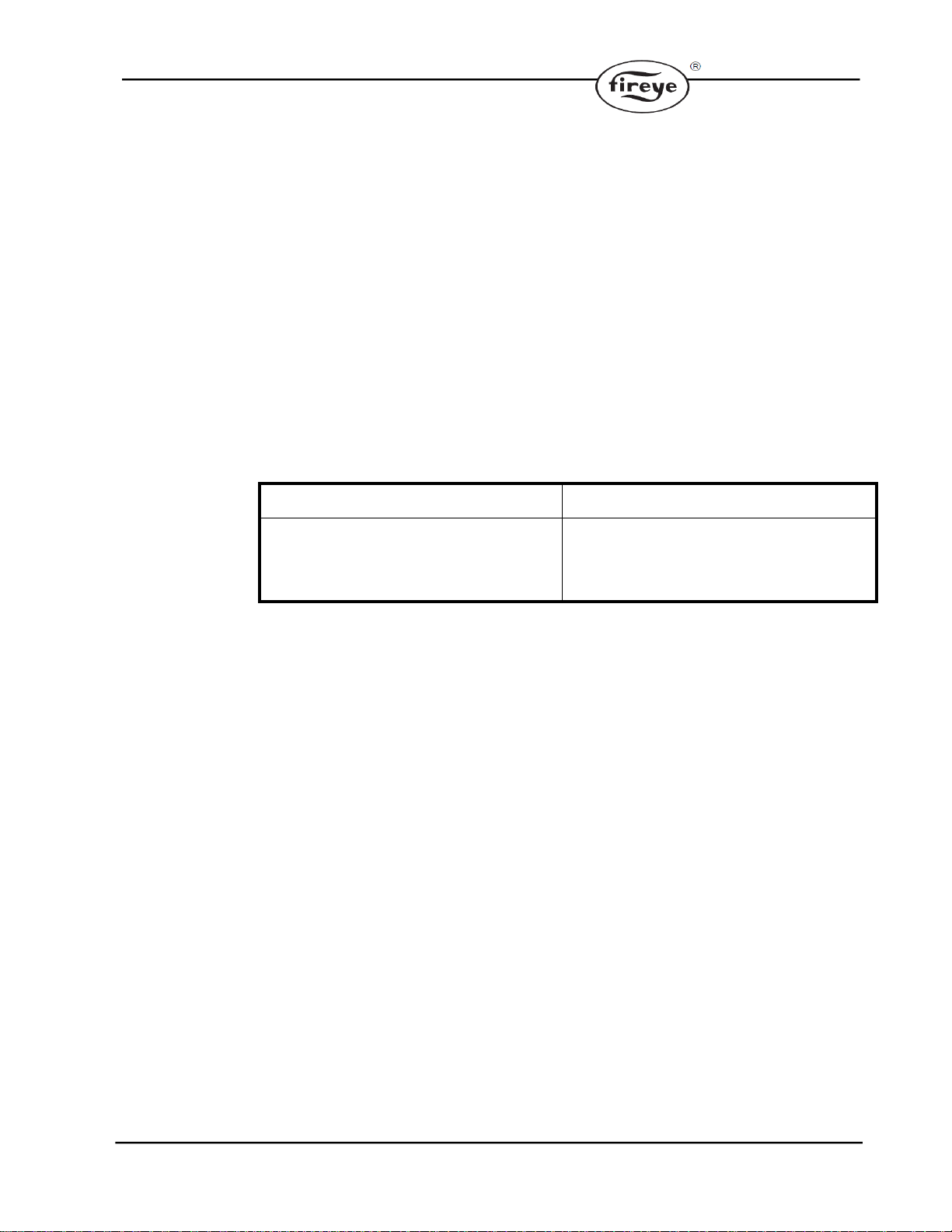
FLAME SCANNERS
UV SCANNER
(SB49600-91)
900UV SCANNER
(SB49600-90
SELF-CHECK UV SCANNER
(SB49602-91
CAUTION: The SB49600-91 and SB49600-90 ultra-violet flame scanners and associated
amplifier modules are non self-checking UV systems and should be applied only to burners that cycle
often (e.g. a minimum of once per 12 hours) in order for the safety checking circuit to be exercised.
WARNING: Installer must be trained and qualified. Follow the burner manufacturer’s instructions,
if supplied. Otherwise, proceed as follows.

8
INSTALLATION OF CONTROL, SCANNERS AND FLAME DETECTORS
Wiring Base
Mount the wiring base on the burner or on a panel. The location should be free from excessive
vibration and within the specified ambient temperature rating. The base may be mounted in
any angular position.
All wiring should comply with applicable electrical codes, regulations and local ordinances.
Use moisture resistant wire suitable for at least 90°C. Good electrical wiring practice should
be followed to ensure an adequate ground system. Refer to Fireye Service Note SN-100
separately and General Grounding Rules later in this document for grounding methods.
A good ground system should be provided to minimize the effects of AC quality problems. A
properly designed ground system meeting all the safety requirements will ensure that any AC
voltage quality problems, such as spikes, surges and impulses have a low impedance path to
ground. A low impedance path to ground is required to ensure that large currents involved
with any surge voltages will follow the desired path in preference to alternative paths, where
extensive damage may occur to equipment.
Circuit recommendations are found on pages 11 through 13. Consult the factory for assistance
with non-standard applications.
WARNING: Controls require safety limits utilizing isolated mechanical contacts.
Electronic limit switches may cause erratic operation and should be avoided.
Care must be taken to NOT route the high energy ignition wire in close proximity to the flame
sensor wiring.
INSTALLATION GUIDELINES
Terminal 7 - Interlocks and Limit Switch Input
Wire external interlock, control, and limit switches in series to this input. Guard against induced
voltage levels to wiring connected to this input. In some extreme wiring runs, reduction of
induced voltages may require a load (relay or light) connected to terminal 7 to avoid system
error lockouts. This input is the power source for the valve and ignition output terminals. Be
sure all switches wired to this input can handle the current required by the total of all loads
connected to terminals 3, 4, and 5.
Terminal 6 - Combustion Air Switch Input
For purge and modulation models: Wire any switches and contacts in series to this terminal for
proving airflow function and relating to the air failure light. Power must not be immediately
present at terminal 6 when power is first applied to terminals 1 or 7. If the combustion air
blower is controlled outside of the SBSeries system, then a three-way solenoid valve must be
connected between the air switch port and the blower sensing port. The valve de-energized
state should vent the switch to ambient.

9
Terminal 4 –Ignition wiring
The output terminal normally powers a high voltage transformer. Route the high voltage
ignition wiring a sufficient distance from all sensors and other low voltage wiring to avoid
electrical interference, which may cause erratic operation of the SBSeries system. Keep the
high voltage wire as short as possible. The best condition is to mount the ignition transformer
close to the burner and keep a low impedance path from the burner ground to the ground of
the transformer. Make sure the high voltage lead and ground return paths do not create a loop
antenna around the SBSeries and sensor wiring.
Low Fire Start Switch, (Terminal 3 –resistance through valve coil)
For modulation sequence models: It is possible to wire the system for checking low fire start
position prior to pilot ignition. To use this feature, the low fire start switch must be connected
between terminal 3 and the pilot valve. On direct spark burners, a by-pass contact must be
wired around the low fire switch.
Terminal V or D - Main Valve Closed Switch Input
The system can be wired to check for the main valve closed switch on the main gas valve prior
to start-up and after the end of the burner cycle.
For purge and no purge models: The main valve closed switch must be connected to
Terminal V and the jumper in the base must be cut.
For modulation models: The main valve closed switch must be wired in series between the
airflow switch and the high purge damper switch. To use this feature, the jumper in the base
must be cut.
Terminal D - High Purge Switch Input
For modulation models: the system can be wired to check high purge position for the high fire
purge portion of the sequence. To use this feature, the red jumper in the base must be cut and
the high purge position switch must be connected from terminal If this feature is not used, the
jumper in the base remains intact a jumper must be installed between terminals 1 and D. (The
yellow jumper on the base has no effect whether cut or intact.)
Terminal 1 - Remote Reset
This feature permits remote mounting of a switch to reset the SBSeries. To use this feature, a
normally closed remote reset switch must be wired so that power is interrupted to terminal 1.
When it is pressed or actuated, the connection to terminal 1 is momentarily interrupted and resets
the SBSeries.
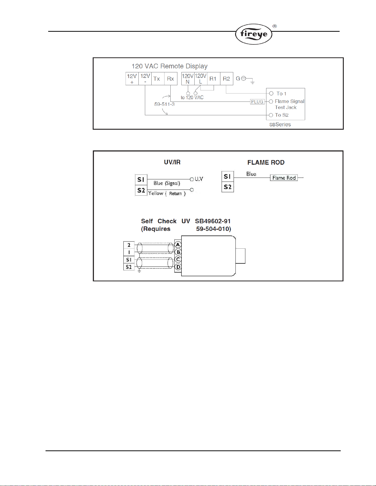
Remote Display
The SB20896 remote display is wired according to Figure 10. Mount through a DIN cutout
using the two supplied brackets in either the top and bottom or the side slots. Locate the display
and wiring to minimize electrical interference. Applying and disconnecting the display power
supply should coincide with power to terminal 1 of the SBSeries. Use the appropriate cable
(P/N SB20318) to connect to the test jack and to the S2 terminal of the SBSeries wiring base.
Do not attempt to parallel the test jack signal to other devices when using a remote display.
The LCD display contrast can be adjusted on the back with a small blade screwdriver.
Note:
1. Control circuit wires must meet 90°C (194°F) specification minimum and must be 1.5mm
(No. 16 AWG) or larger and in accordance with all applicable codes.
2. Flame sensor wires must be individually run in their own separate conduit; multiple
unshielded flame sensor wires CANNOT be run together in a common conduit or wire
way (See Sensor Installation Section).
3. The neutral wire to terminal 2 must be at ground potential (bonded at the supply source).
10
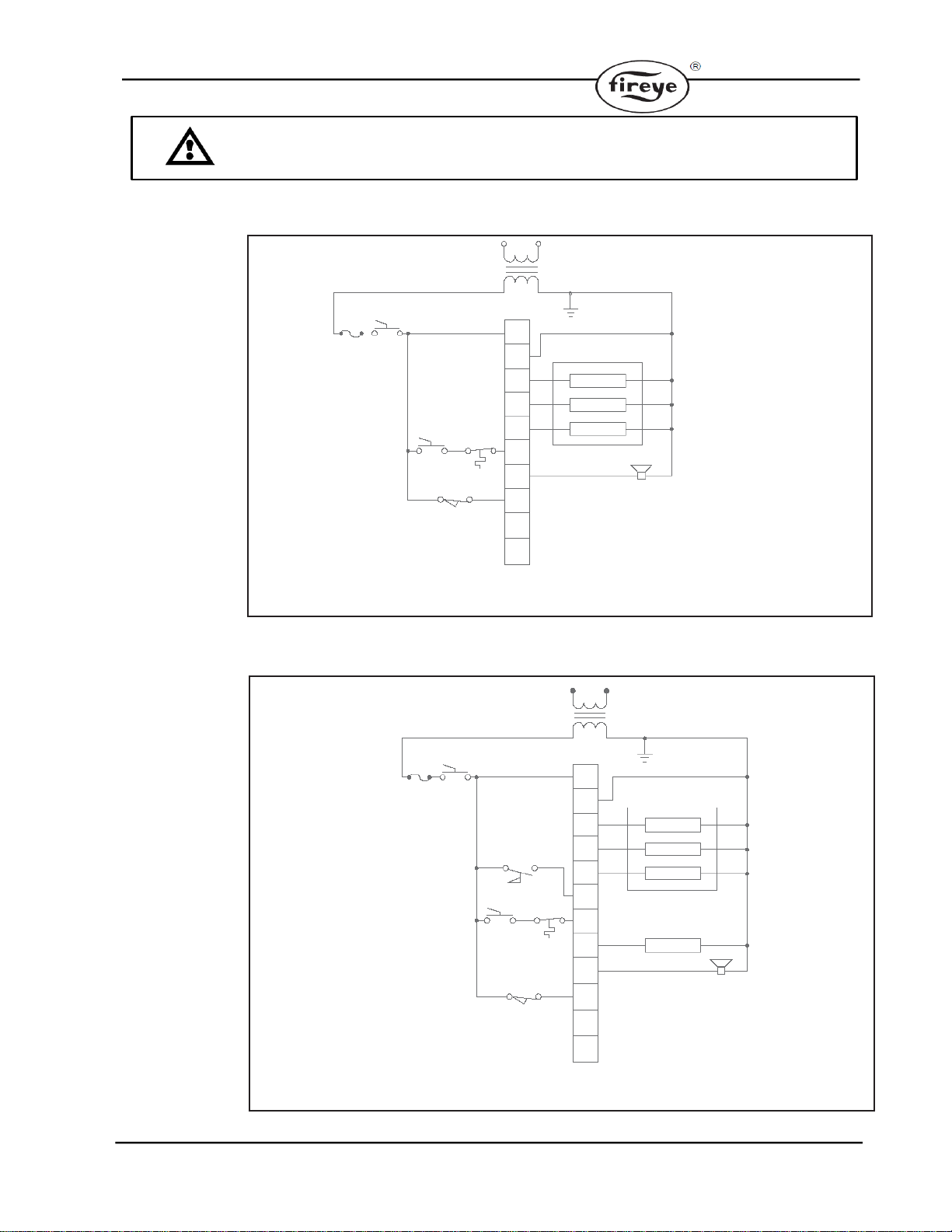
WARNING: Install a modulation sequence model into the modulation style base only;
never plug into purge or no-purge bases.
FIGURE 5 WIRING FOR NO PURGE MODELS
PilotedBurner
Ignition
Main
Pilot
Alarm
S1
S2
A
V
2
4
3
5
7
1
15 A On/Off
Fuse
Interlocks &Limits
Proof of
Closure
120 VAC
240 VAC
50/60 HZ 50/60 HZ
FIGURE 6 WIRING FOR PURGE MODELS
Ignition
Main
Pilot
Fan
Alarm
PilotedBurner
S1
S2
A
V
8
7
6
5
4
3
2
1
Proof of Closure
Interlocks
& Limits
Air Flow
Switch
15 A
Fuse
On/Off
120 VAC
50/60 HZ
240 VAC
50/60 HZ

11
FIGURE 7 WIRING FOR DIRECT SPARK OF MAIN FLAME, NO PURGE MODELS & PURGE MODELS
FIGURE 8 WIRING FOR MODULATION MODELS
FIGURE 9 WIRING FOR DIRECT SPARK OF MAIN FLAME, MODULATION MODELS
12
FIGURE 10 WIRING FOR 120 VAC REMOTE DISPLAY MODULE
FIGURE 11 TYPICAL CONNECTIONS FOR ALL MODELS
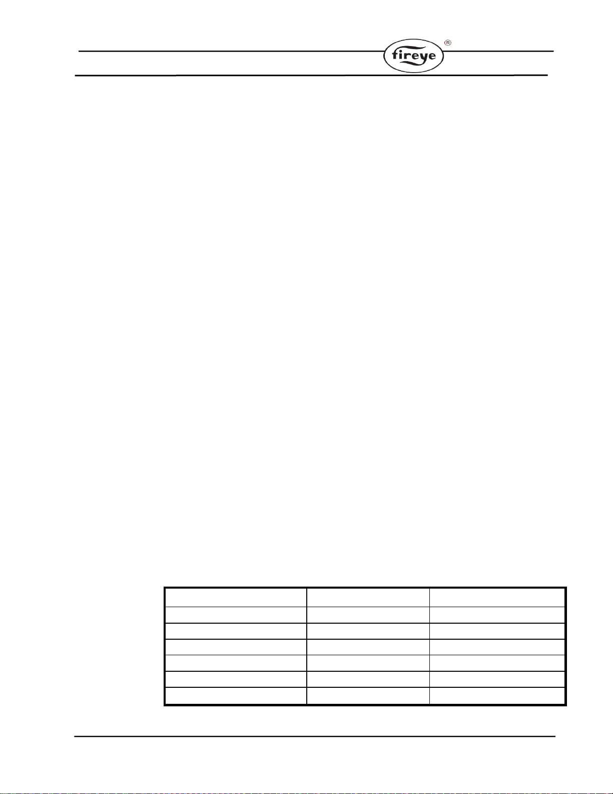
Notes for Figures 5 thrOUgh 11
1. For UV ground, shielding & conduit must not be connected to terminal S2. For FR, S2 must
connect to flame ground (burner front plate). Do not connect shielding or conduit to terminal S2.
2. Control circuit wires must meet 900C (1940F) specification minimum and must be No. 16 AWG
or larger and in accordance with all applicable codes.
3. Flame sensor wires must be individually run in their own separate conduit, flame sensor wires
CANNOT be run together in a common conduit or wire tray.
4. Flame signal should read between 4 and 10 VDC with a digital volt meter. Drop-out is
approximately 4.0 VDC. Positive test jack point is on the cover marked “Flame Signal” with S2.
5. Neutral must be grounded.
13
SEQUENCE STEP
INTERNAL CONTACTS
FUNCTION
Power Off
Terminals 10 to 12
LOW
Power On, Limits Off
Terminals 10 to 12
LOW
Purge to High Fire
Terminals 10 to 13
HIGH
Purge to Low Fire
Terminals 10 to 12
LOW
Automatic Modulation
Terminals 10 to 11
AUTO
Alarm and Lockout
Terminals 10 to 12
LOW
OPERATION
Introduction
This section describes the features of the SBSeries CE. It is presented in three categories: standard
Features, Optional Features, System Errors and Lockout Conditions, and the LED Indicator lights.
Standard Features
The following functions are standard features on the SBSeries models as noted. Interlocks and
Limit Switch Input (Terminal 7)
This input is considered the normal operation control or run input to the SBSeries system. Interlocks
are generally pressure or temperature switches that when activated will start the burner. Limit
switches are generally pressure, temperature, and other switches that when activated will stop the
burner. The interlocks and limit switches are wired in series. A break in this circuit will shut the
burner down, but will not produce an alarm or lockout condition.
Combustion Air Switch Input (Terminal 6)
For PURGE and MODULATION sequence models: This input is for monitoring the combustion
air switch separately from other interlocks and limits. The SBSeries checks the air flow switch input
is open before start-up, closed during operation, and open again at burner shutdown, thus preventing
operation with an air switch that is defective, maladjusted or bypassed. This input has about a 2
second delay to filter out and ignore a momentary interruption.
If the input is improperly powered before the fan output is energized, the system error light will blink.
The input must de-energize within 30 seconds or the SBSeries will alarm and lockout.
After the fan output has energized, the air switch input must be made within 10 seconds. If not proven,
then the system will lockout and the alarm output and the air failure light will come on. However, if
the unit has the air switch input hold feature, the sequence is held indefinitely without causing a
lockout. Then when the air switch input is made, the sequence continues.
If the air switch opens during the main firing cycle, the system will lockout and the alarm output and
the air failure light will come on. However, if the unit has the recycle option and the main output has
been operating for at least 35 seconds, the SBSeries will shut-down and restart.
Pre-Purge
For PURGE sequence models: The SBSeries delays the sequence after the air switch is proven by
the specified purge time. Once completed, the sequence continues to the trial for ignition.
For MODULATION sequence models: The purge time is doubled into two sequences. The first is
a high fire purge for the specified time. The second is a low fire purge allowing the air butterfly valve
time to achieve starting position. The high and low fire purge times are the same as determined by
dipswitches SW 4 - SW 7.
The modulation terminals will sequence as follows:
14
DIP SWITCH SELECTION
Introduction
This section details the location, selection and description of the SBSeries DIP switches which
allow for sequence and timing functions as well as system configuration.
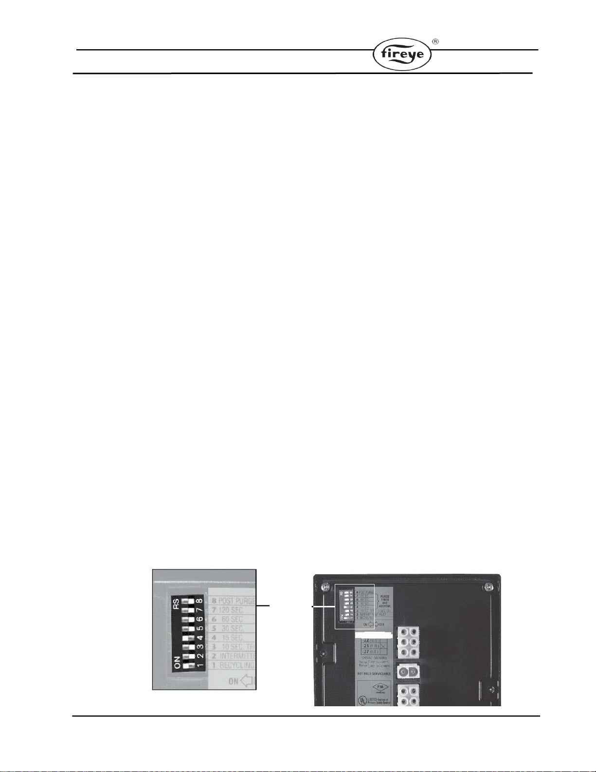
DIP Switch Location
All of the DIP switches are located in the back of each SBSeries unit. (see following ictures).
DIP Switch Access
To gain access to the DIP switches, the SBSeries must be separated from the back box. This separa-
tion will expose the DIP switches on the back of the SBSeries unit.
No Purge DIP Switch Settings
No Purge models of the SBSeries only use three of the eight DIP switches as shown in the
following pictures. They are as follows:
SW1: Recycling mode selection (On =Recycling; Off =Non-Recycling)
SW2: Pilot selection (On =Intermittent, where pilot remains on during burner cycle; Off
=Interrupted, where pilot valve closes after the main burner is established)
SW3: Trial for ignition range selection (For SB5602/SB5603units: On =10 seconds; Off =5
seconds. For SB5605 units: On =10 seconds; Off =15 seconds).
Modulation and Purge DIP Switch Settings
SW1: Recycling mode selection (On =Recycling; Off =Non-Recycling)
SW2: Pilot selection (On =Intermittent, where pilot remains on during burner cycle; Off
=Interrupted, where pilot valve closes after the main burner is established)
SW3: Trial for ignition range selection (For SB5602/SB5603units:On =10 seconds; Off =5
seconds. For SB5605 units: On =10 seconds; Off =15 seconds).
SW4: through SW7: Purge time selection. Total purge time is the sum of each switch selected. If
all are set off, the trial for ignition starts when the air switch input comes on. Switch timings are:
SW4 = 15 sec, SW5 = 30 sec, SW6 = 60 sec, SW7 = 120 sec.
SW8: Post purge selection. (On =15 seconds post purge)
If the air switch opens during the main firing cycle, the system will lockout and the alarm output
and the air failure light will come on. However, if the unit has the recycle option and the main
output has been operating for at least 35 seconds, the SBSeries will shut-down and restart.
NOTE: Flame Failure Response = 3 seconds +/- 0.5 seconds for all models
15
Main Fuel Valve Closed Switch (Terminal V)
For NO-PURGE and PURGE sequence models: The SBSeries can be interlocked with the main
valve closed position switch. This feature checks the switch position before start-up and after shut-
down to insure proper valve operation when the jumper on the base is cut.
For MODULATION models: When wired, the system checks for the low fire start position prior to
light off.
Main Fuel Valve Closed / High Fire Purge Check (Terminal D)
For MODULATION sequence models: This feature is enabled when the jumper on the base is
cut. The system checks that the high fire purge position switch and the main valve closed switch are
both made at the end of the high fire purge.
Low Fire Start (Terminal 3 –impedance)
For MODULATION sequence models: When wired, the system checks for the low fire start posi-
tion prior to light-off.
Pilot Test Mode
In the pilot test mode, the SBSeries will hold the sequence once the pilot flame is established and
prevents energizing the main valve (terminal 5).
Depressing the TEST/RESET button on the front cover enters this mode. When in the pilot test
mode, the green "INTERLOCKS CLOSED" light blinks. To exit the pilot test mode, simply push
the TEST/RESET button 3 times. The green "INTERLOCK CLOSED" light stops blinking, but
remains lit.
Interrupted or Intermittent Pilot
An interrupted pilot shuts off at the time specified by the part number after the main valve is ener-
gized. An intermittent pilot (specified as 00 time) continues during the entire main flame firing
cycle.
Spark, Pilot Flame & Main Flame Separation
During the trial for ignition period (TFI), the pilot and ignition outputs remain energized. At the end
of the TFI, the pilot output remains on and the ignition output is de-energized. After a five second
delay to prove the pilot or start flame, the main gas valve is energized.
Post Purge
For PURGE and MODULATION sequence models: Post purge maintains the combustion air fan
output for the time specified after the interlocks and limit switch input have opened.
OPTIONAL FEATURES
The following functions are optional features that must be specified when ordering.
Recycle Mode
With "R" specified, the SBSeries will restart the sequence after flame or air failure. The recycle mode
allows the system to re-initiate the start-up sequence automatically only if the main burner has been
operating for at least 35 seconds. If the pilot or start flame fails to light during recycling, the system
will alarm and lockout. If the recycle is successful and the main burner is once again operational for
at least 35 seconds, the system is enabled for another recycle. At no time will the system recycle in
the event of a pilot or starting flame failure.
Air Switch Input Hold
For PURGE and MODULATION sequence models: With "H" specified, the SBSeries holds the
sequence indefinitely until the air switch input is made. Once made, normal functional sequence
continues.
16
FAULT CONDITION
LOCKOUT CONDITION
(Illuminated by the red “Fault Condition” LED on
the front cover) prevents gas ignition. The unit will
continue its sequence after the error is cleared
Energizes the alarm output and deenergizes the gas
valve and ignition outputs. The unit must be reset to
clear the alarm and start the sequence. To reset, the
button must be pressed twice so that the button is in
the out position
Manual Reset on Power Outage
With "B" specified, the TEST/RESET button must be pressed twice (in and out) to start the
sequence. The system error light blinks rapidly (about 4 times per second) and a remote display
will show "PUSH RESET TO START".
Remote Display
A remote display is available for the SBSeries. The model SB510 operates on 120VAC and has a
keypad for reset function. The display is mounted through the panel-door and features a liquid
crystal display in a DIN housing. The unit connects to the SBSeries by a cable to the flame signal
test jack, and receives a serial communication on each sequence state change.
The display incorporates the following functions:
1. Provides status messages for the SBSeries sequence, see "Remote Display Messages".
2. Indicates lockout conditions when they occur, as well as the amount of time into the sequence
when the lockout occurred.
3. Provides continuous monitoring of the burner's flame signal strength and run time during main
burner operation.
System Errors and Lockout Conditions
The following fault conditions result in immediate lockout conditions:
1. Wiring error that puts external voltage on the output terminals.
2. Welded internal contacts or other malfunctions in the SBSeries.
3. Main fuel valve closed position switch is open after cycle shutdown or before start-up. The sys-
tem error light blinks twice and then remains on. The fan output terminal 8 will energize.
4. Low fire fail (for modulation model) - the low fire switch is open prior to trial for ignition.
5. High fire fail (for modulating model) - the high fire switch is not closed at the end of high fire
purge.
The following situations will result in a lockout condition:
6. Air failure (for purge and modulation models) - loss of combustion air anytime during the oper-
ational cycle. The Air Failure LED will be on for this condition. (See "Recycle Mode").
7. Pilot flame fail - loss of flame during the trial for pilot ignition period. The Flame Failure LED
will be on for this condition.
8. Main flame fail - loss of flame during the main burner trial for ignition or run period (recycling
not selected). The Flame Failure LED will be on for this condition. The following result in
lock-out conditions after 30 seconds, the system error light blinks about 14 times and then
remains on:
9. If a flame is detected out of sequence, which may be caused by:
a) a faulty scanner;
b) electrical interference on the sensor wiring;
c) a flame exists in the burner or in the line of sight of a scanner, due to a gas leak, product
fire or other condition.
10. Air flow switch closed before start-up (for purge and modulation models).

17
Status Lights and Push-Button
All of the status lights and the TEST/RESET push-button are located on the front cover of the
SBSeries. This section describes their respective functions.
Interlocks Closed
This green LED illuminates when the operation limits are made.
The limits are wired in series to terminal 7. This input becomes energized to begin the burner
sequence. When in the test mode, this LED blinks (see "Pilot Test Mode").
Air Failure
For purge and modulation models: this red LED illuminates whenever combustion air is lost
during the operational cycle of the SBSeries.
Fault Condition
This red LED illuminates when a system error is detected (see "System Errors & Lockout
Conditions").
Flame Failure
This red LED illuminates when a pilot or main flame fails.
Low Fire
For modulation models: this yellow LED illuminates during the low fire period of the purge cycle.
High Fire
For modulation models: this red LED illuminates during the high fire period of the purge cycle.
Auto
For modulation models: this green LED illuminates during the automatic period which occurs 20
seconds after the main valve is energized.
Test/Reset
This push-button is used to activate the pilot test mode or to reset the SBSeries unit.
Flame Signal
This red LED is located behind the signal test port and illuminates when a flame signal is present.
Note: Communication signals from the remote display are superimposed on the flame signal
test jack. During a valid flame On condition these communication signals will appear to be
negligible in comparison to the flame signal (if measuring the flame signal with a DVM for
example). When flame is off, the display communication signals or display “discover” signals will
appear prevalant on the flame signal test jack. Use of an analog DVM will mask this
phenomenon to an extent.

18
Control Power
Ignition
Main Valve
Interlocks
PO VC
Pilot Valve
Inputs
Outputs
TFI Flame
Check
5 sec
Pilot
Trial
Main
Trial
10 sec
Firing
Cycle
Recycle
Permitted
Terminal
TYPICAL SEQUENCE FOR NO-PURGE MODELS
1
3
4
5
7
V
35 seconds
Function
Control Power
Ignition
Main Valve
Interlocks
PO VC
Pilot Valve
Inputs
Outputs
TFI Flame
Check
5 sec
Pilot
Trial
Main
Trial
10 sec
Firing
Cycle
Recycle
Permitted
Terminal
TYPICAL SEQUENCE FOR PURGE MODELS
1
3
4
5
8
6
7
V
35 seconds
Function
Fan
Air Switch
10
sec Post
Purge
15 sec
Purge
Control Power
Ignition
Main Valve
Interlocks
High Fire & PO VC
Pilot Valve
Inputs
Outputs
TFI Flame
Check
5 sec
Pilot
Trial
Main
Trial
10 sec
Firing
Cycle
Recycle
Permitted
Terminal
TYPICAL SEQUENCE FOR MODULATION MODELS
1
3
4
5
8
6
7
D
3
10 TO 12
10 TO 13
10 TO 11
20 sec
Function
Fan
Air Switch
10
sec Post
Purge
15 sec
High Fire
Purge
Continuity
between
Modulation
Terminals
Low Fire
Purge
35 seconds
Low Fire Switch
Low Fire Purge
High Fire Purge
Automatic

19
SENSOR INSTALLATION
WARNING: Incorrect sensor installation may cause the sensor to generate a false flame sig-
nal, causing unburned fuel to collect in the combustion chamber. The result can be explo-
sions, injuries and property damage. Be certain that the flame sensor detects only pilot and
main flames, not glowing refractory, burner or ignition parts.
SENSOR WIRING
Route sensor wiring a sufficient distance from ignition and other high voltage wiring to avoid
electrical interference. Wherever possible, try to terminate the flexible metal shield surrounding
the leads within inches of the Multi-Burner Control terminals. If the shield must be grounded to
reduce interference, ground the shield at the control end to the shield terminal. For self-checking
UV scanners, ground both braided shields. To achieve the maximum wiring distance, the shield
should not be grounded (keep in mind that an ungrounded shield provides less protection against
electrical interference).
Do not ground the shield to terminal GND.
Note: Unshielded sensor wiring must not be run in common with other wires; it must be run in
separate conduit. Multiple flame sensor wiring must not be run together in a common conduit or
wire-way. Use #14 to #18 AWG wire suitable for 90°C (194°F) and 600 volt insulation, and run
each pair of leads in its own shielded cable. Multiple shielded cables can be run in a common
conduit.
FLAME RODS
Flamerods should be used only ongasburners. They accumu-
late soot on oil burners, causing nuisance shutdowns and
unsafe operating conditions. See the burner manufacturer's
literature for flame rod mounting location. When installing
flame rods, please consider the following:
1. Keep the flame rod as short as possible and at least 1/2" (13mm) away from any refractory.
2. Position the rod into the side of both the pilot and main flames, preferably at a descending angle
to minimize droopingof the flame rod against burner parts. Flame rod position must adequately
detect the pilot flame at all burner draft conditions. Extend the rod 1/2" (13mm) into
nonluminous flames, such as blue flames from burning an air/gas mixture. For partially
luminous flames, such as atmospheric air/gas mixtures, place the rod at the edge of the flame.
3. Provide a burner/flame grounding area that is at least four times greater than the flame rod
area contacting the flame. The flame rod/burner ground ratio and position of the rod in the
flame may need adjustment to yield maximum flame signal strength.
4. Ignition interference from the spark plug may increase or decrease the flame signal strength.
Reversing the ignition transformer primary leads may reverse this effect. Reducing the spark
gap or adding grounding area between the flame rod and spark plug may eliminate the
interference.
20
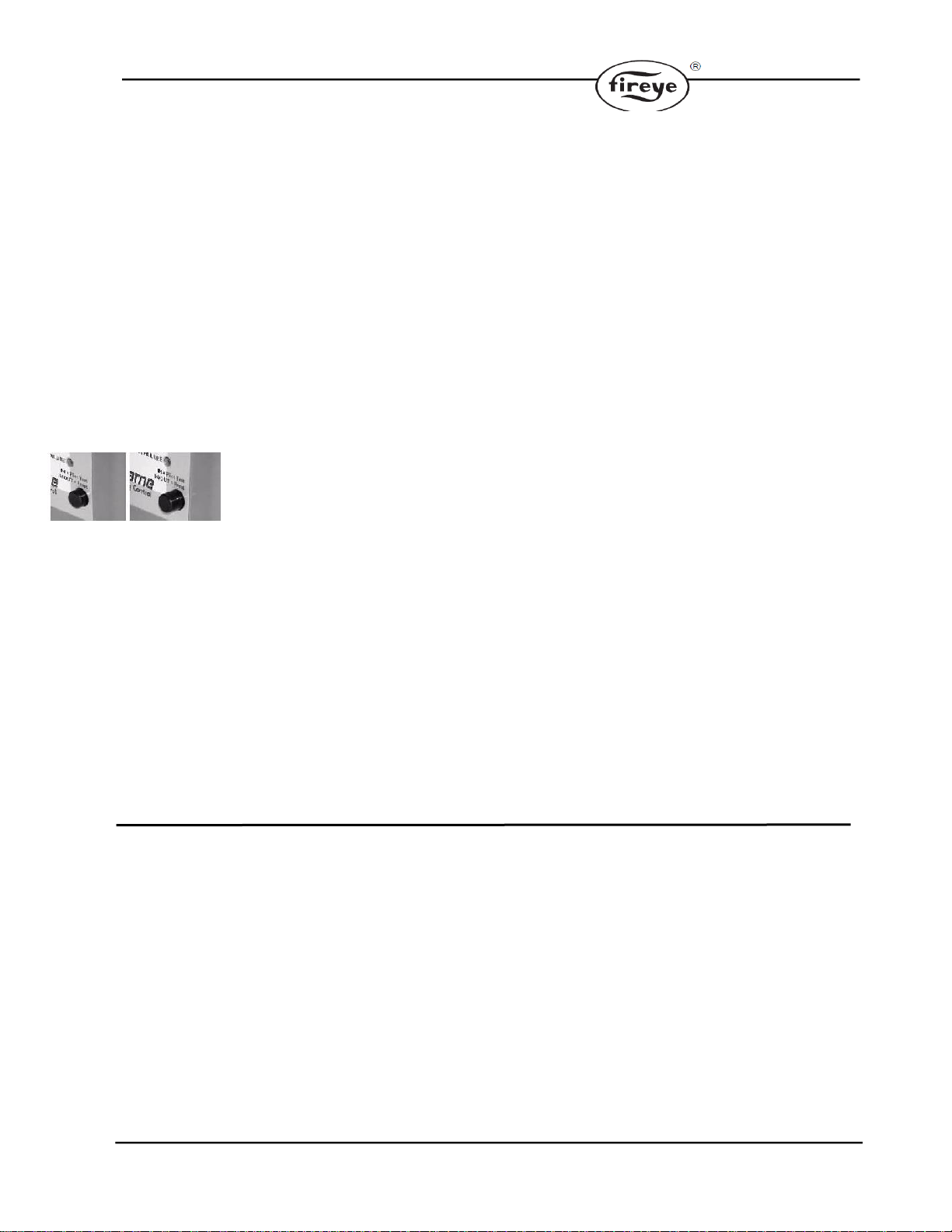
SCANNERS
Use only Fireye scanner SB49600-91, SB49600-90,
SB20898 (not shown) & SB49602-91. Consult the
burner manufacturer's instructions for mounting lo-
cation. When installing scanners, please consider the
following:
1. Position the scanner within 18" (457mm) of the
flame.
2. Bushing threads are 1/2" F.N.P.T. for scanner
models SB49600-91 and SB49600-90; model
SB49602-91 has 1" F.N.P.T. bushing threads.
3. The ambient temperature limits of each scanner
varies; check the literature supplied with the
scanner. For higher temperatures, use Fireye heat
insulator P/N 35-319. If necessary, also use a
purge tee.
4. An optional magnifying lens (Fireye P/N 46-185)
may also be used to increase the flame signal
strength in difficult sighting situations.
UV SCANNER
(SB49600-91)
90° UV SCANNER
(SB49600-90)
SELF-CHECK UV SCANNER
(SB49602-91)
Scanner Installation / Sighting:
When installing scanners, please consider the following:
1. Position the scanner within 457mm (18") of the flame. Consult factory for longer distances.
2. Bushing threads are 1/2" F.N.P.T. for all scanner models except 5602-91 which has 1" F.N.P.T.
bushing threads.
3. The ambient temperature limits of each scanner varies; check the literature for the specific
scanner model. For higher temperatures, use 35-69 heat insulator for 1/2" N.P.T. scanners and if
necessary, add cooling purge air.
4. An optional magnifying lens (60-1290) may also be used to increase the flame signal strength in
difficult sighting situations.
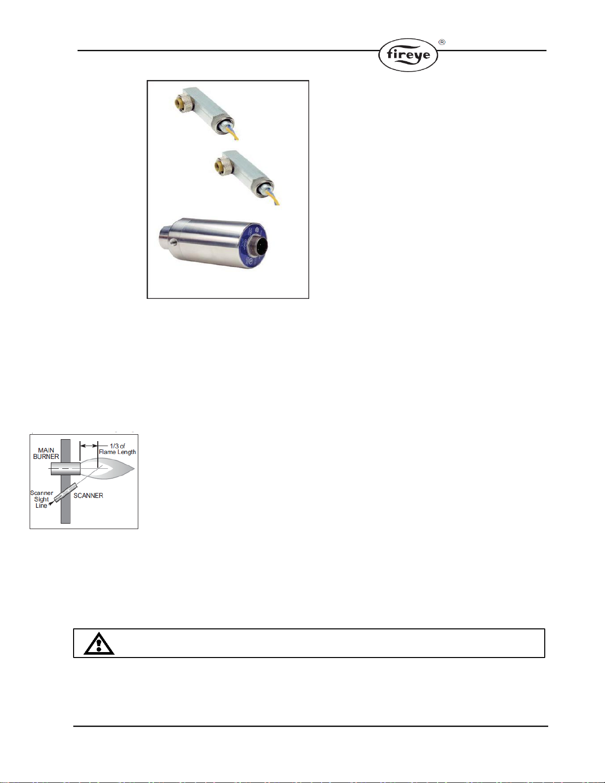
Aim scanners at the third of the flame closest to the burner nozzle, see Figure 12 (oil flames
typically have less UV radiation in the outer flame). The scanner should view the intersection of the
pilot and main flames. When sighting scanners, please consider the following:
1. If possible, sight the scanner away from the ignition spark. Sighting the spark or its reflections
from burner internals may lead to a misdiagnosis of shutdowns during burner ignition. If
necessary use an orifice to reduce spark pickup.
2. Do not allow the scanner to detect a pilot flame that is too small to ignite the main burner.
3. Perform a minimum pilot test when installing or adjusting any pilot or main burner system; see
“Minimum Pilot Test”
Flame Signal Strength
Insert the positive probe of a 0-15 VDC, digital volt meter into the test point on the front cover of
the SB Series control connect the negative probe to S2 or ground. A good flame signal strength will
read between 6 and 11 VDC; anything below 4 VDC is inadequate. Also, the red LED inside the
test point illuminates when a flame is indicated.
Minimum Pilot Test
Run the following test procedures to ensure that the sensor will not detect a pilot flame too small to
reliably light the main flame:
1. Manually shut off the fuel supply to the burner, but not to the pilot.
2. Start the system normally.
Figure 12
CAUTION: The minimum pilot test must be accomplished by a trained and qualified
burner technician.
Other manuals for SB Series
2
This manual suits for next models
98
Table of contents
Popular Fire Alarm manuals by other brands

Fusion
Fusion FBUS Series Installation & commissioning manual

First Alert
First Alert FA2000C installation instructions

Ampac
Ampac FireFinder NZS 4512 installation guide

Cooper Wheelock
Cooper Wheelock MTWP-2475W-NW specification

MasterGuard
MasterGuard 380LS-C SERIES installation instructions

Maxfire
Maxfire CROSSFIRE LCD manual


