thefirebeam firebeam User manual

user guide
issue 0025-05

distance & positioning guidelines
these guidelines are given as a guide only and it is important
that you refer to your appropriate governing standards at all
times.
5m
standard 5-40m beam
standard beam+40-80m reflector kit
standard beam+80-100m reflector kit
40m 80m 100m
what distance?
The standard fire beam will be suitable for distances of over 5m to 40m to the
reflector.If you require 40m to 80m you will need to use the mid range reflector
extension kit. For ranges of 80m t0 100m you will require the long range reflector kit.
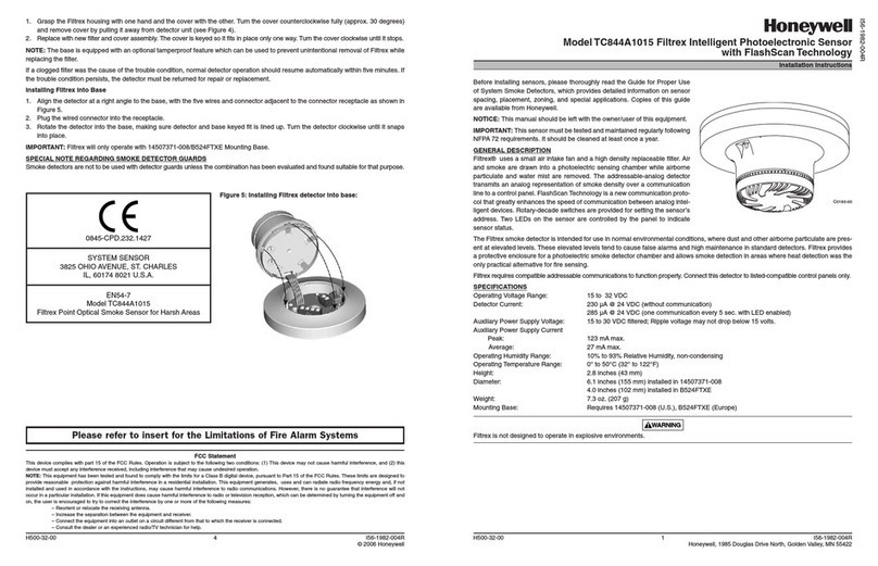
5-40 metres the standard firebeam The standard firebeam comes boxed with the head unit, low
level controller, one reflector, 3mm allen key, test filter and quick start installation guide
this should be used for distances over 5m and up to 40 meters
40 - 80 metres = the standard firebeam + mid range 40 to 80m kit
for distances 0f 40 metres to 80 meters you will need to use the standard firebeam and a mid range extension kit (the mid range kit comes with a back-
ing plate and 3 extra reflectors, you will need to add the reflector from the standard kit to the mid range kit with the screws provided)
40 - 80 metres
add the reflector from the standard firebeam to the
mid range kit with the screws provided
5-40 metres
2

80 - 100 metres
80 - 100 metres = the standard firebeam + long range 80 to 100m kit
for distances 0f 80 metres to 100 metres you will need to use the standard firebeam and a long range extension kit (the long range kit comes with a
backing plate and 8 extra reflectors, you will need to add the reflector from the standard kit to the long range kit with the screws provided)
add the reflector from the standard firebeam to the
long range kit with the screws provided
what position?
A roof is considered flat unless the height of the apex is greater then 0.6m. If the roof
is flat thefirebeam system can be placed anywhere under the roof between 0.3m and
0.6m below the roof,
up to a maximum height of 40m from the floor.Thefirebeam
has a
detection area of 7.5m ether side of the beam.
If the roof is considered to have an apex, place thefirebeam system 0.3m to 0.6m down from
the top of the apex, up to a maximum height of 40m from the floor. The maximum protected
area either side of the beam can be extended by 1% for every degree of roof pitch, see the
example below
Always mount thefirebeam system on a solid construction that is unlikely to flex
Mount over 2.7m from floor level to avoid to people walking through the beam, and
consideration should also be given to the possibility of obstruction by fork lift trucks
and the like.
Avoid pointing the head into direct sunlight.
40m
max
0.3m - 0,6m
flat roof
7.5m
0.3 - 0.6m
7.5m
extra coverage due to apex angle
10
o
0.3 - 0.6m
15m + (15 X10%)
=15m + 1.5m = 16.5m
16.5m detection area
15m detection area
8.25m 8.25m
min 0.5m
wall
you should always position the beam at least 0.5m
away from any protrusion
field of view should be a 50cm radius from
the centre of the beam head
plan view
3

installing and commissioning
screw in through holes
provided outside of the
rubber seal
then screw down
the head screws
with the 3mm allen
key provided
wire into system as required
See generic wiring diagram on
the following page. For other
configurations contact us or
view our website.
2 knock outs are provided
on both sides
wire to low level controller
using bottom colour coded
terminals
connect the head
to the base plate
by first plugging in
the connector
step one. mounting the head
screw the head backing plate to the wall - always try to use as
sturdy location as possible, such as brick or major structural
steels (avoid mounting to outer metal cladding etc)
step two. mounting the controller
Important mount the controller at eye level and with easy access
screw in through holes
provided outside of the
rubber seal
wire to head using colour
coded terminals
Also available adapter plate
use this accessory for easy mounting to unistrut fabrication. Holes are pre drilled to the
correct pitch of the head and conveniently positioned for use with unistrut
4

generic wiring configuration
to fire panel
to controller
switch 4 on all rest off
BROWN + supply (10.2-30 Vdc)
BLUE - supply (return)
BLACK zone +
GREY zone -
GREEN earth (screen)
Supply Voltage 12Vdc to 24 Vdc +25% -15%
Quiescent Current 3mA
Alarm Current 3mA
Aligning Current 3mA
Fault / Fire relay contact rating 2A @ 30Vdc
FIRE and EOL
components as specified by
the panel manufacturer
5

step three. commissioning
to commission the fire beam you must follow the simple procedure below
1. do NOT put up the reflector or COVER it if in place already!
2. power up the unit - you will see
then the screen will default to
3. access the menu system by pressing enter
4. scroll through the menus until you get to commissioning
5. enter commissioning and enter pre-alignment
(pre alignment is probably the most important part of commissioning)
6. you will see this screen
received signal
P=pre-alignment
signal power receiver sensitivity
X (horizontal)
motor position
Y(vertical)
motor position
6

7. signal power starts at 10% and the receiver sensitivity starts at
5% and automatically increases until a received signal from the
blank wall without the reflector of between 5 and 7% is
achieved, it will then stop
if you are covering a distance of over 50 meters you should be
achieving signal power of over 60%, if you are receiving less it’s
possible that you are picking up a reflection from something
other than the target blank wall. By moving the beam
(looking at the wall) left (x-) right (x+) up (y+) and down
(y-) you can move the beam away any obstacles to
achieve higher signal power
8. Once you are happy with the power readings press enter
and confirm by pressing the right key. The manual alignment
menu will appear press enter to enter.
you will now seen this screen
Y +
X+
X -
Y -
obstacle roof line
target wall
received signal
press enter in
pre-alignment and then
confirm by pressing the
right key
press enter to
enter manual
mode
7

9. NOW place or uncover the reflector on the blank
wall directly opposite the beam head with a clear path though
obstructions such as girders etc.
It is important that there is a clear line of vision between the reflector and any
obstruction -the beam head must see at least 200mm of clear wall around the reflec-
tor to enable successful auto alignment.
Once the reflector is in place the AQ value should jump up
meaning that the head is now seeing the
reflector.
If you have received a AQ reading of over 40% go to Auto
Alignment point 10.
you need a reading of at least 40% to proceed to Auto align-
ment. If you do not receive an AQ signal of 40% it means the
beam head is not seeing the reflector. You will need to move
the beam head until you receive an AQ reading of above 40%
ideally over 100%
If you are presented with the screen below (AQ-air quality could be any number up to 40%)
Now look at the position of the reflector in relation to the beam head. You will need to
angle the beam toward the reflector by moving the head about its X or Y axis
using the internal motors
In the example on the next page you will notice that the reflector is below the line of
fire of the beam. So in this case you would need to lower the angle of the beam (-Y)
until you receive a AQ (Air Quality) reading above 40% sensitivity. (40 steps of the motor =
1degree of movement)
The minimum response you need to see is 40%
(below this figure the beam will not self align in the
next procedure) the higher the number the better - this
can be over 100%
clear vision around
the reflector
8

Y +
X+
X -
Y -
Y -
40 steps = 1 degree of movement
Adjustments can now be made to the Xand Yaxis by using the
left(x-), right(x+), up(y+), down(y-) keys. Looking at the reflector
this will move the beam across the reflector like so
(40 steps = 1degree) (you can hold the key down for faster increments)
in the example above moving the yaxis down(y-) results in a greater
% air quality
Wait for x / y values to finish moving to asses your AQ result
beam head reflector
Press enter to exit manual mode and enter Auto Alignment
Try and achieve as good a result as possible - it must be over
40% or auto align will abort. (the better the result the shorter the
auto align time will be - a result over 100 is good!)
10. Having received a AQ reading of over 40% in manual mode
press enter to exit manual and enter again to enter
auto alignment
press enter and the beam head will automatically align on the reflector
9

Note: if you break the beam whilst it’s auto aligning it
will automatically abort, reset by pressing the left back
button and pressing enter to re-start auto alignment
the alignment could take up to 30 minutes or more
depending on how much aligning is required. Once com-
plete you will see a Align Complete notification, simply
press the left back button to exit and your firebeam is now
ready and commissioned
you will now see this screen. Air Quality may fluctuate
slightly around a couple of %.above and below 100
first you will see the signal power readings and receiver
sensitivity drop if the received signal reading is over 100%.
once at 100% or if the reading is under 100% thefirebeam
will automatically move its X and Y axis until it is positioned
on the reflector. (This operation could take 30 minutes or
more)
step four. testing
to test that the firebeam is aligned correctly you will need to carry out two tests.
Your firebeam has now been commissioned and tested.
1. a filter test for ‘Fire’
place the filter provided over the eyes of the firebeam.
having done this (after 10 seconds) the red fire LED will flash on
both the head and on the controller and the word FIRE will
replace NORMAL on the low level
controller display
2. a reflector test, to check that the beam is reflected
back from the reflector
cover the reflector completely within one second. If the beam is
correctly targeted on the reflector a fault condition will occur (after
10 seconds). A amber LED will flash on both the head and on the
controller, the word FAULT will appear
in the display
10

screen and menu system
issue 0026-02
NORMAL FIRE FAULT ERROR ALIGN
default 35% adjustable between 25% and 50%
to enter sub menus
to exit sub menus
default autoreset
press enter / menu to enter
menu system
shows (
*
) when updating
If alarm is set to latching and you need to reset
from fire press ‘enter’ to see this screen and
‘enter’ again to reset and return to the normal
screen, if in fire you will need to press ‘back’to
go back to the main menu. If set to auto reset it
will reset to normal automatically
no
comms
beam head is
performing
a self
re-alignment
procedure
to increaseto decrease
use left and right buttons to change
shows (
*
) when updating
use left and right buttons to change
shows (
*
) when updating
default 10s
default 10s
default off
use left and right buttons to change
shows (
*
) when updating
use left and right buttons to change
11

view amount of internal gain made to
compensate for dirt build up on beam lenses
-128% to +128%
to test beam press enter - the power will
slowly drop as can be seen in the
dropping air quality.
When the air quality drops past the pre set
threshold the beam will fall into fire
remember that there is a delay time
set for time to fire
to enter sub menus
counts events since alignment or reset 0-255
back to exit
sub menus
12

pre- alignment is the first stage of
alignment - this should only be used
without the reflector
to enter sub menus
make adjustments by using the
left, right, up and down keys
(this moves the beam in these
directions across the face of
the reflector- with your back to
the beam)
make adjustments by using the
left, right, up and down keys
(this moves the beam in these
directions across the face of
the reflector- with your back to
the beam)
this symbol will
appear next to
the number when
you move the
beam
this symbol will
apear next to the
number when
you move the
beam
to exit sub menus
13

if the beam is obstructed during auto alignment
the alignment will be aborted press back to
return to auto alignment and enter to resume
auto-alignment once alignment is complete you will
see the screen below
press back to return to the main
screen
14

to enter sub menus
shows output power strength
compensation amplifier
shows sensitivity of receiver
to exit sub menus
shows temperature at beam head
screen used by The Fire Beam
help desk
screen used by The Fire Beam
help desk
software versions for the head
and controller
shows (
*
) when updating
to increaseto decrease
shows (
*
) when updating
to increaseto decrease
shows (
*
) when updating
to increaseto decrease
15

Electrical Specifications:
Supply Voltage. 10.2 to 40 VDC
Supply Current. 3mA (constant current)
in all operational states
Environmental Specifications:
Temperature. -10°C to +55°C
Humidity. 10 to 95% RH Non-condensing
Protection Index. IP65 when suitably
mounted and terminated
Mechanical Specifications:
Beam Head.
180mmH x 155mmW x137mmD
Weight 1.1Kg
Controller.
185mmH x 120mmW x 62mmD
Weight 0.55Kg
40KIT80 Mid-Range Reflector.
293mmH x293mmW x 5mmD
Weight 0.8Kg
80KIT100 Long Range Reflector.
394mmH x 394mmW x 5mmD
Weight 1.8Kg
ADAPTER.
270mmH x 250mmW x 5mmD
Weight 0.6Kg
(mounts the Beam Head onto unistrut)
Optical Specifications:
Optical Wavelength. 870nm
Maximum Angular Alignment. ±15°
Maximum Angular Misalignment.
(static not auto-aligning)
Beam Head ±0.75° Reflector ±2°
Operational Specifications:
Protection Range:
FIREBEAM.
Standard Product 5 to 40 metres
40KIT80.
Mid-Range Reflector Kit 40 to 80 metres
80KIT100.
Long Range Reflector Kit 80 to 100 metres
Alarm Sensitivity Levels:
25%(1.25dB) to 50%(3dB) in 1%(0.05dB)
increments (default 35% (1.87dB))
Alarm Condition:
Obscuration drops to below pre-defined
sensitivity level.
Time to Alarm Condition adjustable
2 to 30 seconds in 1 second increments
(default 10 seconds)
Alarm Indication:
Controller Status – FIRE
Controller Red Flashing LED 0.5 Second
Head Red Flashing LED 1 Second
Alarm Relay Change Over (CO) Contact
Rating 2A @ 30 VDC
Test/Reset Features:
Beam test function by controller
Alarm latching/auto-reset selectable
(default auto-reset)
Alarm reset in latching mode by controller reset
function, removing power for >5 seconds,
apply 12 to 24 VDC to reset connections in
Beam Head.
Fault Sensitivity Level:
90%
Fault Condition:
Obscuration drops to below the fault
sensitivity level within 1 second
Power Down or Supply Voltage < 9 VDC
Commissioning modes, Pre-Alignment
and Auto Alignment
Beam turned off during Beam Maintenance
(auto resets in 8 hours to normal)
Time to Fault Condition adjustable,
2 to 60 seconds in 1 second increments
(default 10 seconds)
Fault Indication:
Controller Status – FAULT
Controller Yellow Flashing LED 1 Second
Head Yellow Flashing LED 1 Second
Fault Relay Change Over (CO) Contact
Rating 2A @ 30 VDC
Normal Condition:
Obscuration level is above the
Alarm sensitivity level
Controller Status – NORMAL
Controller Green Flashing LED 1 Second
Programmable on/off
Head Green Flashing LED 1 Second
Programmable on/off
Auto-align/Beam Contamination
Compensation:
Auto-align during normal operation if
obscuration drops below 90%
(doesn’t effect normal operating mode)
Beam Contamination Compensation 4 hour
monitoring. Compensation data available at
the controller
technical specifications
Table of contents
Popular Fire Alarm manuals by other brands

Fire-Lite Alarms
Fire-Lite Alarms LCD-40 Series manual

Ziton
Ziton ZP2-LB Installation sheet

Adicos
Adicos M-BUSMASTER XF operating manual
Maxfire
Maxfire CROSSFIRE LCD manual

Teletek electronics
Teletek electronics SensoIRIS BSOU installation instructions

Fire-Lite
Fire-Lite SENSISCAN 2000 Nstallation, operation and programming manual
Firesense
Firesense DA Series Operation, installation & programming manual
DM TECH
DM TECH FP9000L-4 Installation, setup and operation
Secutron
Secutron MRM-800MP Series installation instructions

Siemens
Siemens Cerberus CS1140 Commissioning Extinguishing
pivotal
pivotal CurrentLeak Whole Home installation instructions
Aritech
Aritech FP2000 reference guide

