First Choice ELectrolux EMG 360 Guide

SPARE PARTS DIAGRAM FOR
First Choice Group
Blakeney Way, Kingswood Lakeside
Cannock, Staffs, WS11 8LD
TEL: 01543 577778 FAX: 01543504141
Email: [email protected]
Web: www.firstchoice-cs.co.uk
Salamander Grill
283462 / 283475 / 283465 / 283474
MODEL: EMG 360 / SL/E 360 / EMG 480 / SL/E 480

MAN 132
ISSUE 1/98
ELECTRIC MULTIGRILL/SALAMANDER
600/800
USER’S INSTALLATION AND SERVICING MANUAL
MARK 4
PNC: 283462 / 283475 / 283465 / 283474
MODEL: EMG 460 / SL/E 460 / EMG 480 / SL/E 480

2
SPECIFICATIONS 600 MODEL 800 MODEL
Output
Grilling (8oz steaks) 30/h
Toasting (slices) 140/h
Dimensions cm
Overall (h x w x d) 360/600/392 360/800/392
Height on stand
Floor stand 130.5 130,5
Bench stand 57.5
Electrical Supply 240V/50Hz/1ph
Total Lod kW 3.6 5,0
Net Weigh kg 23 25
GENERAL
The 600 /800 ELECTRIC MULTIGRILL/SALAMANDER
are supplied for use with a single phase (32A) electricity
supply. Details will be found on the Data Plate fixed behind
the Control’s Fascia Panel.
STANDARD EQUIPMENT
Toasting rack with crumb tray.
OPTIONAL EXTRAS
Bench stand
Wall bracket
Floor stand
Branding plates
ELECTRICAL DATA
Refer to the Data Badge (affixed to the rear of the Control’s
Panel on the right hand side of the grill) to check that the
appliance is compatible with the electricity supply available.
The supply inlet is positioned at the rear right hand side of
the appliance.
A fused isolator must be fitted in the electrical supply close
to the unit for use in an emergency and to facilitate servicing.
600 MULTIGRILL/SALAMANDER ELECTRIC
EMG4-60/ SL/E 460
Two elements each of 1,8kW al 240V AC
TOTAL RATING: 3.6kW 240V AC 50Hz
800 MULTIGRILL/SALAMANDER ELECTRIC
EMG4-80 / SL/480
Two elements each of 2,5kW al 240V AC
TOTAL RATING: 5,0kW 240V AC 50Hz
UPON SITING THIS APPLIANCE, AN
EQUIPOTENTIAL EARTH BOND MUST BE MADE
FROM THE GRILL AND ITS STAND TO ADJACENT
EQUIPMENT USING THE FIXED BOLTS LOCATED
AT THE REAR OF THE UNITS.
WARNING/SAFETY NOTES
1. This appliance must be installed by a qualified electrician
in accordance with the requirements of the Fire
Precautions Act, The Health and Safety at Work Act, and
the latest Local and National Building Regulations. The
installation wiring must comply with the latest IEE
Wiring Regulations and the Electricity at Work
Regulations.
2. THIS APPLIANCE MUST BE EARTHED.
3. This appliance is designed for commercial purposes only,
and must be operated by qualified personnel.
4. This appliance and it’s stand must be incorporated into a
potential equalization system.
5. It is the responsability of the kitchen supervisor to warn
users of this appliance to wear suitable protective
clothing.
6. During normal operation, parts of this appliance will
become hot. Suitable precautions must, therefore, be
taken by the user to avoid accidental burns.

3
7. A fused isolator control which isolates all poles and has a
minimum contact clearance of 3mm, must be fitted in the
electrical supply close to each unit for use in emergency
and to facilitate servicing.
8. If the electrical supply cable is damaged, it must be
replaced by a qualified electrician using 3 core, 2.5mm2
cable to the HO5-RNF specification or higher.
9. The normal leakage current for this appliance is not
greater than 5mA.
10.It is recommended that a residual current device to
BS4293 standard is used on each power supply.
11.In the event of a fault developing, it is essential that the
appliance is isolated from the mains electricity supply and
a competent person informed.
12.In the interest of safety and performance, regular
maintenance and servicing of the appliance is important.
To ensure that the appliance is in optimum condition,
periodical service and maintenance contracts can be
undertaken by the supplier. Equipment is inspected and
serviced by our engineers and, where necessary, faults are
rectified. Any replacement parts are quickly obtained and
fitted to bring the appliance into good working condition.
INSTALLATION
GENERAL
NOTE! It is necessary to employ a qualified electrical
engineer to install and service this appliance.
1. Remove all packaging from the applicance. Any
protective film on the stainless steel panels may be left on
until installation is completed. HOWEVER all protective
film MUST BE REMOVED before the appliance is
commissioned and used.
2. This appliance must be supported clear of any bench top
or shelf upon which it is to stand. A minimum of 50mm
(2”) is recommended. The use of the optional Bench
Stand is strongly urged.
3. Ensure that the area where the appliance is to stand is
leveled, and is capable to support the weight of the
appliance. If the support, or its surround, is made of
combustible material it is recommended that they shall be
clad with a suitable non-combustible heat insulating
material, and the local fire regulations must be observed.
4. Ensure that there is enough room at the front of the
appliance to accommodate the Toast Grid Handles and
the Brander Plate Drip Trough when fitted, and the Toast
Grid might be removed and handled safely.
5. This appliance should preferably be installed below the
hood of an extraction system incorporating filters.
Should the installation be required without a ventilation
hood then a minimum distance of 1000mm (3 feet) must
be allowed between the top of the appliance and any over
head shelf or ceiling. This
appliance may be fitted close to side walls if they are
made of a fire-proof material. A distance of 150mm must
be allowed between the rear of the appliance and a back
6. wall to enable the electrical cable entry. Where the walls
are made of a combustible material, then a minimum
distance of 150mm MUST be maintained between the
appliance and adjacent walls.
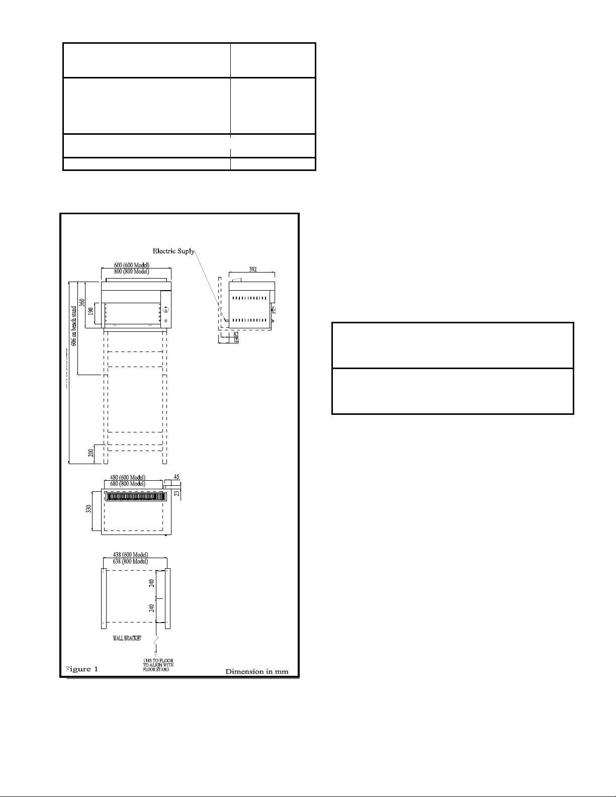
7. When installation is to be made using Wall Brackets,
refer to the enclosed diagram. Ensure that the wall is
capable of supporting and holding the Wall Bracket’s
fixings and the combined weight of the Brackets and
Grill. Measure and mark upon the wall the position of the
Bracket fixings. Drill suitable holes and apply the
selected fixings. Securely screw the Brackets in position.
Place the Grill in position upon the Brackets, aligning the
front of the appliance with the front edge of the projecting
Brackets. Fix the Grill
into position using the four screws provided by screwing
them into the four fixed nuts in the bottom front and rear
flanges of the appliance base.
ELECTRICAL CONNECTION
ENSURE THAT THE MAINS ISOLATING SWITCH
IN THE OFF POSITION.
TURN THE APPLIANCE CONTROL KNOB TO THE
OFF POSITION.
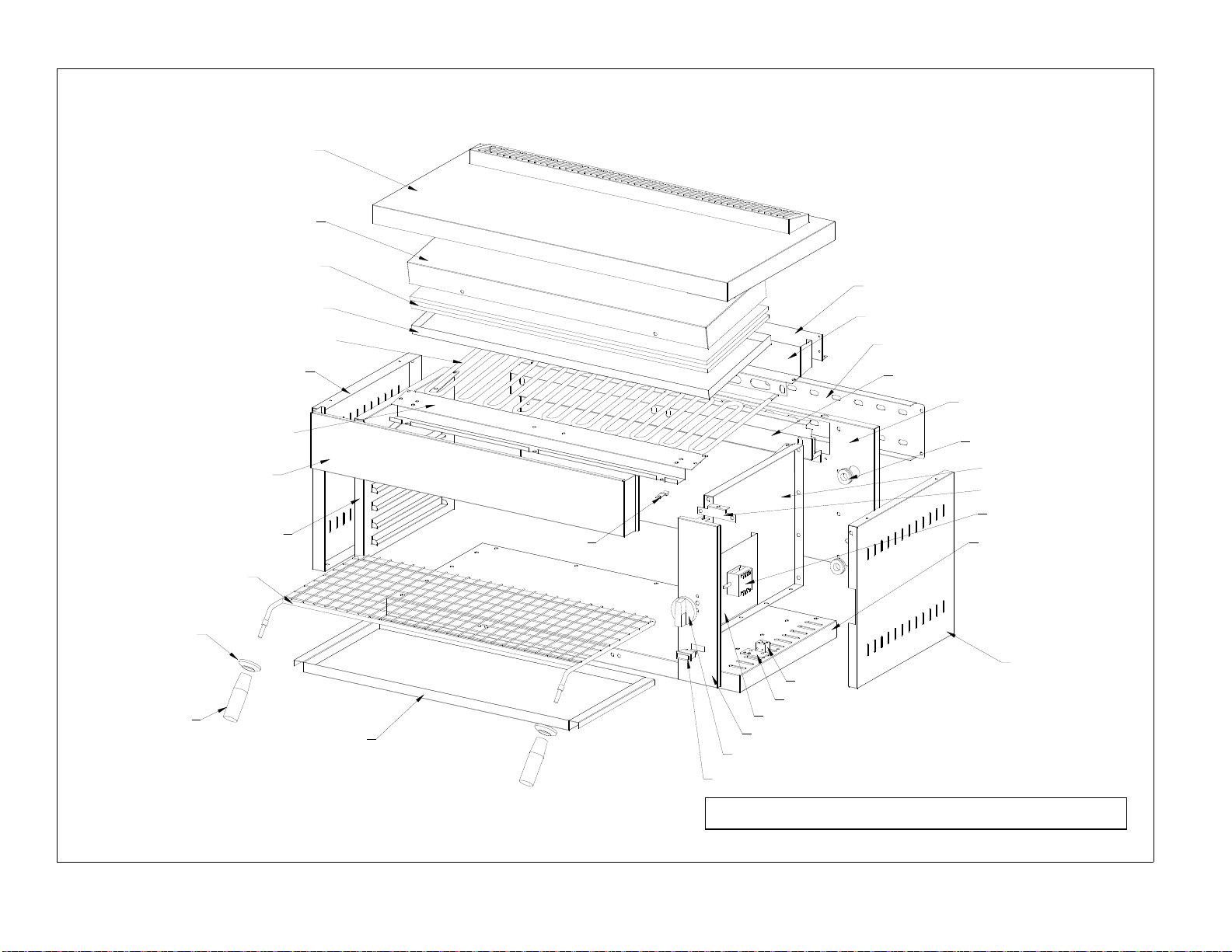
1. Remove the Outer Top Panel by sliding it towards the
front, and then lift it clear of the appliance.
2. Pull off the appliance Control Knob.
3. Remove the Control’s Fascia Panel by removing two
slotted head screws from below the lower front of the
Fascia and one slotted screw from the top of the fascia.
CAREFULLY place the Control’s Fascia aside so that no
undue strain is placed upon the Switch Wiring.
4. Remove the RH Outer Side Panel by unscrewing slotted
head screws from the rear (2), from the upper front (1),
and from below the lower side flanges (3). The Outer Side
may now be pulled clear of the appliance.
5. The appliance’s Mains Terminal Block is now exposed.
Pass the prepared mains cable through the strain relief
grommet in the lower Back Panel of the appliance and
route it through the eyelet fixed in the Terminal Block
Bracket. Make the connections.
LIVE = RED
N
EUTRAL = BLUE
EARTH = GREEN/YELLOW
With only a minimum “sag” on the Mains Cable within
the appliance, tighten up the Strain Relief Grommet in the
Rear Panel.
6. Refit the RH Outer Side Panel and the Control´s Fascia
Panel.
7. Refit the RH Outer Top Panel by positioning the keyhole
slots in the underside of the Outer Top above the four
pegs projecting from the Outer Side Panels. Fimly press
the Outer Top down, and then slide it towards the rear of
the appliance until the backs line up.

4
COMMISSIONING PROCEDURE
WARNING WHEN TESTING WITH COVER
PANELS REMOVED, CARE MUST BE TAKEN TO
AVOID TOUCHING LIVE PARTS AND
TERMINALS.
1. Ensure that all protective film is removed from the
stainless steel panels.
2. Turn Control Knob to the OFF position.
3. Switch on the electricity supply at the mains isolating
switch.
4. Check that the Green “MAINS ON” neon is lit on the
Control’s Fascia Panel.
5. Switch ON the Control knob to the HI position. The two
elements should visibly glow after a short period.
6. Allow the elements to operate during moreless ten
minutes, then turn the Control Knob to the LO position.
The intensity of the glow from both elements should
diminish.
7. Turn the Control Knob to the LH ONLY position, the
brightness of the left hand element should increase, and
the right hand element should go off.
8. Turn the Control knob to the OFF position, and swicht of
the supply at the mains isolating switch.
When installation is completed leave Instruction Manual
with a responsable menber of the kitchen staff.
OPERATING INSTRUCTIONS
IMPORTANT
THIS APPLIANCE MUST BE INCORPORATED
INTO A POTENTIAL EQUALISATION SYSTEM.
THIS APPLIANCE MUST BE EARTHED.
a) This appliance is designed for commercial purposes only
and must, therefore, be operated by qualified personnel.
b) It is responsabiliti of the kitchen supervisor to warn users
of this equipment to wear suitable protecting clothes.
c) During normal operation, parts of this appliance will
become hot, suitable precautions must, therefore be taken by
the user to avoid accidental risks.
d) When using the brander plate, always fit the drip/basting
through, and empty it frecuently. Do not allow the through to
become too full or overflow, or too full to handel safely.
e) Always preheat the brander plate for aproximately 20
minutes at at Full power before use.
NOTE : In the event of fault developing, it is essential to turn
off the electricity supply at the isolating switch and inform a
competent person.
TO SWITCH ON
Ensure that the electricity supply is on, and the mains
isolating switch is on. The GREEN lamp Mains ON neon,
on the Control´s Fascia Panel, will glow when the electricity
is on.
Turning the appliance control knob to :
HI -- BOTH elements are switched on to full power.
LO --BOTH elements are switched on to low power.
LH -- ONLY Only the left Hand element is activated at full
power, the right hand element is switched off.
TO TURN OFF
Turn the control knob to the OFF position.
COOKING
TOASTING
Place the Toasting grid with the Crumb Tray slid into place
on the lower part of the grid- in the third runner up from the
grill base. Place the bread on the grid. Switch on to HI.
Alternative grid positions are provided to suit individual
preferences and the thickness of the bread.
GRILLING USING THE TOAST GRID
Grilling foods such as bacon, sausages, etc. can be carried out
using the Toast Grid, but always fit the Crumb Tray to collect
grease and juices.
The position of the grid in the grilling compartment will
depend upon personal taste. Initially try the third runner up
from the base.
SALAMANDERING.
For shallow dishes place them upon the toasting grid; for tall
(deep) dishes place upon the base of the grill. Use the Crumb
Tray- if there is any risk of spillage or boil over- placed upon
the base of the grill.
FOR LOW CALL-OFF AND PERIODS OF
LOW DEMAND.
During periods of low demand, the Electric Multigrill allows
the user to chose wherther to have a single element light on (
at the left hand side), or to have both elelments on at a
reduced heat setting. This is achieved by turning on and
positioning the control knob at the appropiate setting. For a
small quantity of food then the LH ONLY position should be
used. The LO position is useful to keep the Brander Plate hot,
or to provide a quicker response following a slack period.

5
USING THE BRANDER PLATE ( Grilling
Hearth).
The Brander Plate is thick cast aluminium plate having a
ribbed surface. It is mounted upon a special frame and has the
advantage to be able to be mounted flat or inclined in one of
several positions. The Crumb Plate should be stored upon the
base of the grill when using the Brander Plate.
ALWAYS FIT THE DRIP/BASTING TROUGH
MOUNTED ON THE FRONT BASE OF THE GRILL when
using the Brander, otherwise grease and juices from the
cooking food will drip directly onto the floor in front of the
grill.
ALWAYS EMPTY THE DRIP TROUGH BEFORE IT
BECOMES TOO FULL TO HANDLE SAFELY.
SCRAPE THE BRANDER PLATE FREQUENTLY
DURING COOKING PERIODS TO CLEAR CARBON
DEPOSITS.
The Brander Plate can be set at several angles within the
grilling compartment to suit various types of grilling. It
should always slope down towards the front. Locate the
Brander Plate upon it’s frame ensuring that the two pegs at
the rear of the frame engage in the two holes in the REAR
part of the Brander Plate.
Engage the rearmost side pegs in the frame upon the
appropriate upper shelf runner, and push the Brander into the
grilling compartment. THEN engage the front side pegs of
the frame onto the lower shelf runner. Raising and lowering
the Brander, and increasing or decreasing the angle may be
carried out by changing the front peg position. The thicker
the cuts of meat, the lower the position of the Plate. It is not
advisable to leave the Brander Plate in a high position for
long periods of time with the heat full on.
When using the Brander Plate, the Plate must be placed in
position in the grilling compartment, and the grill turned on
to HIGH for about 20 minutes to pre-heat the Plate.
TO OBTAIN THE BEST RESULTS USING THE
BRANDER PLATE
1. Place the Brander Plate upon the Brander Frame with the
Frame’s pegs located in the holes at the back of the Plate.
Then position the Brander in the desired position within
the gill compartment.
2. Initially, try positioning the rear pegs on shelf four and
the front pegs on shelf two, until you are familiar with the
cooking performance.
3. Pre-heat the Plate for about 20 minutes with the burners
on HIGH.
4. When cooking, use the rear of the Brander, or raise the
position for Minute Steaks, and use the front, or lower the
position for cooking thick cuts and well done steaks.
Cooking should be completed without the need to turn the
food over if the Brander Plate has pre-heated for enough
time.
CLEANING
WARNING
BEFORE CLEANING THIS APPLIANCE,
SWITCH OFF THE GRILL AT THE
CONTROL KNOB AND AT THE MAINS
ISOLATING SWITCH.
Cleaning is best carried out daily shortly after the grill has
been turned off - while it is still warm but not too hot.
DO NOT PLUNGE A HOT BRANDER INTO WATER - TO
DO SO CAN CAUSE IT TO DISTORT.
Heavy deposits should be scraped off the Brander Plate using
wood or plastic implements to avoid damaging the plate’s
surface. Soaking and washing in hot detergent solution
should be sufficient, with difficult areas being cleaned using
a “grit-free” proprietary cleaning agent. The use of ammonia
and caustic based cleaners should not be used as they attack
the metal - especially the aluminium Brander Plate. When
cleaning the interior of the grilling compartment, care must
be taken to avoid damaging in the heating elements.
Grills that are used continuously for cooking meat products
and where extensive use is made of basting, are likely to
became thickly coated externally and internally with grease
and carbonised fat. This is unhygienic and may became a
potential fire hazard. For this reason, the Outer Top Panel of
the Grill has been designed to be easily removed by the user,
allowing the Inner Top Panel to be removed from the grill for
cleaning.
1. Pull the Outer Top Panel foward and lift it clear of the
pegs in the tops of the the Outer Sides. Remove to the
sink for cleaning.
2. Lift the Inner Top Panel clear of the appliance and
remove to the sink for cleaning.
3. Carefully scrape any deposits from within the grill and
wash with a hot detergent solution. Dry WITH a lint-free
cloth.
4. Dry the Inner Top Panel, and place back into position.
5. Dry and polish the Outer Top Panel. Replace in position
by aligning the pegs with the key-hole slots (2 on each
side) in the return side flanges of the Outer Top Panel,
push the Panel firmly down onto the Outer Sides and then
push towards the rear of the grill until the back of the
panel lines up wigh the back of the grill.
THERE SHOULD BE NO GAP BETWEEN THE
OUTER SIDES AND THE OUTER TOP PANEL.
6. Re-light the grill on HIGH for a short period to
thoroughly dry off the unit.
7. The interior of the grilling compartment and the Inner
Top Panel will benefit from a light wipe-over using an
lightly oiled kitchen paper following cleaning.
8. The exterior panels of the grill are best cleaned using a
hot detergent solution followed by a rinse wipe-over and
a polish using a stainless steel cleaner.
DO NOT USE CAUSTIC BASED CLEANING AGENTS
ON THIS APPLIANCE.

6
MAINTENIANCE INSTRUCTIONS
IMPORTANT
Mainteniance must only be carried out by a qualified
electrician.
BEFORE DISMANTLING ANY COMPONENTS
OR EXPOSING ANY WIRES, TURN OFF THE
ELECTRICITY SUPPLY AT THE MAINS
ISOLATING SWITCH AND REMOVE THE
FUSES.
Maintenance depends upon the degree of use of the
appliance, but should be carried out on a regular basis. If an
appliance is in daily use, in a busy kitchen, then a minimum
of four times a year is recommended.
The following checklist, together with a thorough cleaning
programme, should provide optimum service and trouble-free
operation:
1. Remove the Outer Top, Inner Top Panel, and the
Control’s Fascia.
2. Remove the RH Outer Side Panel.
3. Examine the internal wiring and components for
damage.Operate the appliance. Rewire oe replace parts if
necessary. Replace if necessary.
4. Remove the Top Front Fascia Panel by unscrewing two
slotted head screws in the lower flange at the top front of
Grilling compartment, the panel may be lifted clear of the
appliance.
5. Check and clean the element terminal cavity, and inspect
the wiring, paying particular attention to the heating
elements terminations.
6. Refit all parts and check operation of the appliance.
REPLACEMENT OF PARTS AND
SERVICING
The servicing of this appliance should be carried out by a
qualified electrician or under a service contract provided by
an approved manufacturer service Organisation. Benefits of a
service contract include regular visits from specialist
engineers, priority breakdown treatment and extensive spare
parts back up service. A servIce contract is avalaible to cover
ALL your equipment and the work carried out is guaranteed.
For details contact the manufacturer or an approved
manufacturer servicing organisation for further details.
SPARE PARTS
Only genuine spares should be used on this appliance and
can be obtained from:
Electrolux Commercial Service
Spares Dept. Bordesley Green Road,
Birmingham B9 4UA
telephone: 0121 - 623 1829
telefax: 0121 - 623 1819
When ordering spare parts please quote the serial number and
the model number of the appliance together with the part
number of the component required.
A. OUTER TOP PANEL.
Remove/Replace
1) Pull the outer top panel forward to release keyhole slots
from the locating pegs on the side panels then lift clear of the
appliance.
2) Replace in a reverse sequence ensuring that there is no gap
between the top of the side panels and the outer top panel.
B. INNER LINER.
Remove /Replace
1) Completed proccedure A.
2) Lift the linner then isulating tile clear of the appliance.
3) Replace in a reverse sequence.
C. FASCIA PANEL.
Remove/ Replace
1) Complete proccedure A.
2) Remove Control Knob by pulling it firmly off its spindle.
3) Remove one screw from the top of the Fascia and two
screws from the bottom of the panel.
4) Pull the Fascia panel gently away from the appliance.
5) Unplug wires from the switch noting their setting.
6) Unplug wires from the neon light.
7) Replace in reverse secuence.
D. RIGHT HAND OUTER SIDE
PANNEL.
Remove/Replace
1) Complete proccedure A, B, and C.
2) Unfasten two screws from rear edge of panel.
3) Unfasten three screws from the lower edge of panel.
4) Remove panel from the appliance.
5) Replace in a reverse sequence.
E. CONTROL SWITCH.
Remove/Replace
1) Complete proccedure C.
2) Remove two screws and pull out Switch through rear of
the fascia panel.
3) Replace in reverse order.

7
F. NEON LAMP.
Remove/Replace
1) Complete proccedure C.
2) Squeeze the clips on the end of the Lamp inwards then
pull out the lamp through the front of the fascia panel.
3) Replace in reverse order.
G. TERMINAL BLOCK.
Remove/ Replace
1) Complete proccedure.
2) Unplug thge wires from Terminal Block noting it
configuration.
3) Remove two screws.
4) Replace in reverse order.
H. HEATING ELEMENT.
Remove/Replace
1) Complete proccedure D.
2) Unfasten two screws from the lower edge of upper Fascia
Panel and remove Panel.
3) Unfasten two screws and remove Element Terminal Cover.
4) Unplug wires from Element Terminal.
5) Unfasten screws and remove securing clips.
6) Withdraw Element from appliance.
7) Replace new Heating Element in a reverse proccedure
ensuring that the isulating Blocks are in good condition.
SPARE PART NUMBERS LIST
DESCRIPTION MULTIGRILL
600 MULTIGRILL
800
OUTER TOP PANEL 1225-7211 1225-7212
INNER TOP PANEL 1225-7271 1225-2200
INSULATION TILE SJS-450 SJS-451
CONTROL KNOB 548837311 548837311
GREEN NEON SEW-868 SEW-868
CRUMB TRAY 1225-7262 1225-7263
TOASTING GRID 1225-7260-1 1225-7260-2
TOASTING GRID
HANDLE 24820-3900 24820-3900
HEATING ELEMENT SEL-092 41752-6000
CONTROL SWITCH SEC-093 SEC-093
OUTER LEFT HAND
PANEL 12250-0600 12250-0600
OUTER RIGHT HAND
PANEL 12250-0700 12250-0700
OUTER FRONT PANEL 12250-4600 12250-2000
INNER LEFT PANEL 12250-3300 12250-3300
INNER RIGHT PANEL 12250-3200 12250-3200
GUARD DISC 54801-5801 54801-5801
MAIN TERMINAL
BLOCK 50468-00-AA 50468-00-AA
ELECTRICAL CABLE
PROTECTION 244653-5200 244653-5200
HEATING ELEMENT
SUPPORT 12250-4200 12250-2500
FASCIA PANEL
ELECTROLUX. SXL 446 SXL 446
FASCIA PANEL
ZANUSSI SXL 446-2 SXL 446-2
REAR PANEL 122504500 122503100
BASE PANEL 122500800 122503500
FRONT PANEL 12257275 12257275
FRONT PANEL LINING 12254600 12252000

8
ELECTRIC WIRE DIAGRAM
OFF HIGHT LH ONLY LOW

9
ELECTRIC MULTIGRILL 800
1225-7212
12250-2200
SJS451
12250-2400
41752-6000
12250-0700
12250-2100
12250-2000
12250-3200
1225-7260-2
54801-5801
24820-3900 1225-7263
12250-2300
12250-2500
12250-2900
12250-2600
12250-3100
24653-5200
12250-0600
SEL0921
1225-7214
12250-3300
SEW868
SCH307
1225-7275
12250-3500
12250-3000
SXL307
50468-00AA
SEC093
ELECTRIC MULTIGRILL/ SALAMANDER 800

10 ELECTRIC MULTIGRILL 600
1225-7211
1225-7271
SJS450
SJS450-1
SEL092
12250-4300
12250-0700
12250-4600
12250-3200
1225-7260-1
54801-5801
24820-3900
1225-7262
1225-7272-1
12250-4200
12250-4400
1250-4100
12250-4500
1225-7214
SEL0921
24653-5200
12250-3300
12250-0600
SEW868
SCH307
1225-7275
SEC093
12250-3000
12250-0800
50468-00AA
SXL307
ELECTRIC MULTIGRILL/ SALAMANDER 600
This manual suits for next models
9
Table of contents
Popular Grill manuals by other brands

Charmglow
Charmglow 730-0289 Use and care guide

MR. BAR-B-Q
MR. BAR-B-Q CBC1501M owner's manual

Campingaz
Campingaz 1 Series Compact LX R Instructions for use

Better Homes and Gardens
Better Homes and Gardens BG2503B-DG manual

Beem
Beem Pro Multi-Grill 3 in 1 instruction manual

pleasant hearth
pleasant hearth OFW650R manual