First Choice KME6 User manual

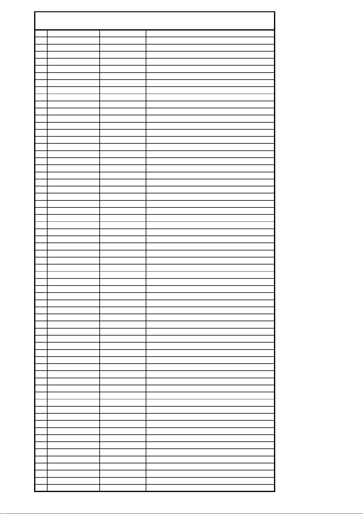
SPARE PARTS DIAGRAM FOR
First Choice Group
Blakeney Way, Kingswood Lakeside
Cannock, Staffs, WS11 8LD
TEL: 01543 577778 FAX: 01543504141
Email: [email protected]
Web: www.firstchoice-cs.co.uk
Combination Oven
KME6 (1551260)

25
24
22
16
15
14
10
55
8
57
56
28
38
37 20
19
18 62
21
67 333223
58
64
47
49
48
17113160
34
30
29
9
6
5
71
2
27
46
12
13
26
3
4
54
68
35 36
51
52
63
50
53
59
65
66
61
69
KONVEKTOMAT KME6 (1551260)
Seznam náhradn ch d lů / Spare parts list
Bc. Sukač
FIRSTCHOICE CATERING SPARES 01543 577778
Control panel
membrane / sticky
foil overlay. Part
number
30502900008
1 45001101000S01P KME6-01-00a Vnitřní bedna - KME 6
2 45001002010001P KME6-02-01a Bedna s izolací-přední plech
3 45001002020000 KME6-02-02 Bedna s izolací-podpěra přední
4 45001002020001 KME6-02-03a Bedna s izolací-držák izolace
5 45001002040200 KME6-02-04 Bedna s izolací-plech izol. L
6 45001002050202 KME6-02-05b Bedna s izolací-plech izol. P
7 45001002060202 KME6-02-06b Bedna s izolací-plech iz.zadní
8 45001003000000 KME6-03-00 Držák ventilátoru
9 45001004000204 KME6-04-00d Držák elektro
10 45001005000000 KME6-05-00 Výduch ventilátoru
11 45001006000S03P KME6-06-00c Okapová miska
12 45001007000S00 KME6-07-00 Držák ovládacího panelu
13 45001008000S01 KME6-08-00a Ovládací panel
14 45001009000S01 KME6-09-00a Odsávací trubka 1
15 45001010000S02 KME6-10-00b Odsávací trubka 2
16 45001011000S00 KME6-11-00 Odsávací trubka 3
17 45001012000S00 KME6-12-00 Těsnění dveří
18 45001015000S10 KME6-15A-00 Vnější dveře KME6
19 45001016000S01 KME6-16-00a Žlábek
20 45001017000S01 KME6-17-00a Vnitřní dveře
21 45001018000S00 KME6-18-00 Závěs dveří
22 45001020010000 KME6-20-01 Plech levý-plech
23 45001021000S02 KME6-21-00b Plech pravý
24 45001022000S00 KME6-22-00 Plech zadní
25 45001023000S01 KME6-23-00 Plech horní
26 45001024000000 KME6-24-00 Závěs dvířek
27 45001128000000P KME6-28-00 Kryt ventilátoru
28 45001129000S01 KME6-29-00 Ostřikovač
29 45001130000020 KME6-30B-00 Držák roštu
30 45001133000S00 KME6-33-00 Sítko
31 45001034000S01 KME6-34-00a Podstavec
32 45001035000S00 KME6-35-00 Odvzdušňovací trubka
33 45001040000S00 KME6-40-07 Klapka odvzdušňovací trubky
34 45001046000000 KME6-46-00 Spodní kryt
35 45001048000001 KME6-48-00a Záslepka odsávání
36 45001049000000 KME6-49-00 Záslepka odvzdušnění
37 45001064000S00 KME6-64-00 Vnitřní dveře KME 6 - výměnný díl
38 45101144000000 KM23-44-00 Roztřikovací kroužek
46 45001056000S00 Světlo montážní celek
46 -30200300027 Žárovka halogen
46 -30406600005 Sklíčko světla KONVEKTOMAT
47 30200100006 Vypínačna konvektomat
48 30200100007 Přepínačkonvektomat
49 30200200020 Knoflík konvektomat
50 30200200021 Knoflík regulační konvektomat
51 30200200022 Termostat komínový konvektomat
52 30200200025 Termostat pojistný konvektomat
53 30200800013 Jednotka řídící UNS 2PT100
54 30200900018 Těleso topné konvektomat
55 30201800001 Ventilátor HSL 44
56 30201800025 Kolo oběžné R2A 150
57 30201800026 Ventilátor radiální s kond.
58 30202700001 Jehla - špice konvektomat
59 30203000001 Sonda PT100
60 30500400007 Noha konvektomat
61 30501400010 Hrot kliky
62 30501400009 Klika KME 6
63 30503200001 Sprcha konvektomat
63 30503200006 Sprcha konvekt. - hadice
64 30503200007 Sprcha konvekt. - držák hadice
65 30503300002 Ventil 1-cestný na konvektomat
66 30503300003 Ventil 2-cestný na konvektomat
67 30503600003 KME6-40-10 Těsnění silikon 67x5x2
68 30503600004 Těsnění skla konvektomat
69 30503600009 Těsnění grafit 8x33,5x2 mm
KONVEKTOMAT KME6 (1551260)
Spare parts list / Seznam náhradních dílu
FIRSTCHOICE CATERING SPARES 01543 577778

INSTALLATION INSTRUCTIONS
SAFETY INSTRUCTIONS
USER INSTRUCTIONS
STEAM COMBI OVEN
MODEL : KME 6 ELECTRIC (6 GRID)
MODEL : KME 10 ELECTRIC (10 GRID)

SITE PREPARATION
REMOVE THE PROTECTIVE PLASTIC COATING FROM THE OVEN
CLEAN UNIT WITH SOAPY WATER
1 x WATER CONNECTION WITH ¾ VALVE
(UNIT SUPPLIED WITH 1 x Y PIECE CONNECTOR)
(AND 2 x ¾ HOSES)
A DRAIN PIPE WITH TRAP – 1½” Dia (38mm)
ELECTRICAL SUPPLY REFER TO TECHNICAL DATA
PLEASE RECORD YOUR MACHINE SERIAL NO. HERE,
THIS WILL HELP IN THE FUTURE FOR SERVICING.
SERIAL No. ____________________
DATE OF PURCHASE ____________________

INSTALLATION
1. Place the oven on a level surface allow a clearance between
the wall and the unit of at least 5cm.
N.B. The control panel should not be next to a heat source.
2. ELECTRICAL CONNECTION
This unit must be installed by a qualified electrician.
Your mains supply (voltage, current, fuse protection) must conform
to technical data plate on unit.
The supply voltage during operation must not vary from the normal
voltage level by more than ±10%
It is essential to earth the appliance using the terminal with the
symbol on the internal terminal block.
3. WATER CONNECTION
There are 2 x water connections at rear of the unit, these are
connected by the 2 x hoses via the 1 x Y piece connector supplied.
IMPORTANT NOTE
A water treatment unit must be fitted to the machine to avoid scale and
harmful minerals to enter the cavity of the oven.
Failure to do so will affect the life span of the oven and it will invalidate
your warranty.
4. DRAIN CONNECTION
A suitable tundish or receptacle should be used directly
underneath the drain outlet allowing an air gap of at least 60mm.
IMPORTANT INSTRUCTIONS – SAFETY

Please read instructions before operating this appliance and retain for future use.
ALWAYS
Ensure that hands are dry before
handling the KME 6 and 10
isolators or switching on the
appliance.
Use the appliance on a secure dry
level surface.
Allow adequate air space above
and all sides for air circulation.
Isolate when not in use and before
cleaning.
Allow to cool before cleaning.
Carry out regular checks of the
supply cable to ensure no damage
is evident. Should there be any
signs that the cable is damaged in
the slightest degree, the entire
appliance should be isolated and a
service engineer called.
NEVER
Do not use this appliance outdoors.
Do not use this appliance for other
than intended use.
Do not immerse the appliance or
cable and plug in water or any
other liquid to protect against
electrical hazards.
Do not use harsh, abrasive or
caustic cleaners to clean this
appliance.
Do not allow children to use this
appliance.
Do not let supply cable hang over
the edge of a table or counter,
touch hot surfaces or become
knotted.
Do not place this appliance on or
near a hot gas or electric burner or
where it could touch a heated oven,
air flow is essential.
Never touch hot surfaces.
Do not operate any appliance with
a damaged cable or after an
appliance malfunction or if it has
been damaged in any manner.
Never block off the vents.
CAUTION:
THIS APPLIANCE GENERATES HEAT
DURING USE. PROPER PRECAUTIONS
MUST BE TAKEN TO PREVENT THE
RISK OF BURNS, FIRES OR OTHER
DAMAGE TO PROPERTY CAUSED BY
TOUCHING THE SIDES OR TOP
WHILST IN USE OR DURING COOLING.

CLEANING INSTRUCTIONS
Isolate the appliance from the electrical supply before carrying out
any maintenance.
Keep the oven clean.
Do not wash the appliance with high pressure water jets.
Do not use steel wool pads or metal scrapers, which could deposit
small ferrous parts that might rust.
The oven interior should be cleaned daily with particular attention
to the fan area and shelf supports. Spray or apply a quality oven
cleaner all over the interior of the oven. Particular care should be
taken to protect hands, eyes and face and avoid breathing any
fumes produced. Do not use detergent containing abrasives or
caustic as these will damage the surface of your oven. Set oven to
Super steam mode and allow it to run for 20 minutes before use.
CAUTION: open the door very carefully avoiding steam as it
contains substances which could be harmful to hands and eyes.
NEVER operate the door with the internal glass unclipped from the
main door as damage will occur.

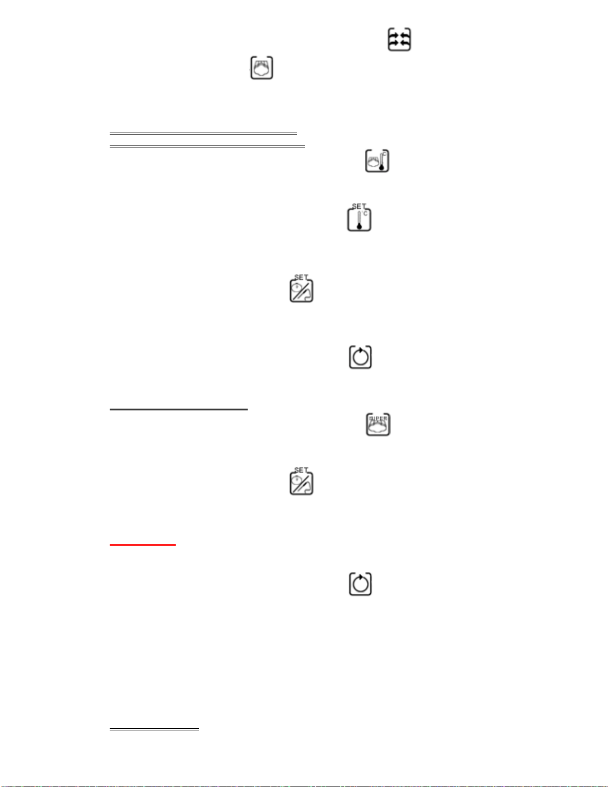
CONTROL PANEL
1. MAINS SWITCH
2. COOKING SELECTOR
a) Combination cooking
b) Convection cooking
c) Super Steam cooking
d) Cooling mode
3. INCREASE/DECREASE
OF SELECTED VALUES.
4. TIME/PROBE SET
5. TEMPERATURE SET
6. STEAM ADDITION
7. REGENERATION
8. CYCLE START
9. DISPLAY 1
10. DISPLAY 2

USER INSTRUCTIONS
KME 6 AND KME 10
SWITCH ON
TURN MAIN SWITCH TO POSITION 1 AND THEN PRESS BUTTON
WAIT 5 SECONDS BEFORE SELECTING THE COOKING FUNCTIONS
*NOTE*
TO STOP THE COOKING CYCLE AT ANY TIME PRESS START/STOP
CYCLE BUTTON
CONVECTION COOKING “DRY HEAT COOKING WITH FAN”
SELECT CONVECTION COOKING MODE BY TURNING THE MODE
SELECTION KNOB
PRESS TEMPERATURE SET BUTTON AND WITH ADJUSTMENT
DIAL AND SELECT REQUIRED TEMPERATURE.(See item 3 on the control
panel key guide) (PRE-SET 250°C) (20 – 270°C)
PRESS TIME SET BUTTON AND WITH ADJUSTMENT DIAL SELECT
COOKING DURATION (MIN 1 – MAX 240 MINS) OR LEAVE SET ON P
(PERMANENT)
PRESS START/STOP CYCLE BUTTON TO START.
IMPORTANT
PRESS REGENERATION BUTTON FOR REGENERATION OF FOOD
WHEN USED ONLY ONE INJECTION OF STEAM WILL BE INJECTED INTO
OVEN.
CONVECTION WITH STEAM
DURING THE CONVECTION COOKING MODE PRESS STEAM
ADDITION BUTTON TO SELECT THIS OPTION (WHEN USED ONLY
ONE INJECTION OF STEAM WILL BE INJECTED INTO OVEN).
COMBINATION COOKING (STEAM)
WITH ADJUSTABLE TEMPERATURE
SELECT COMBINATION COOKING MODE BY TURNING THE MODE
SELECTION KNOB
PRESS TEMPERATURE SET BUTTON AND WITH ADJUSTMENT
DIAL SELECT REQUIRED TEMPERATURE.(See item 3 on the control panel
key guide) (PRE-SET 250°C) (20 – 270°C)
PRESS TIME SET BUTTON AND WITH ADJUSTMENT DIAL SELECT
COOKING DURATION (MIN 1 – MAX 240 MINS) OR LEAVE SET ON P
(PERMANENT)
PRESS START/STOP CYCLE BUTTON TO START.
SUPER STEAM COOKING
SELECT COMBINATION COOKING MODE BY TURNING THE MODE
SELECTION KNOB.
PRESS TIME SET BUTTON AND WITH DIAL WITH ADJUSTMENT
DIAL SELECT COOKING DURATION (MIN 1 – MAX 240 MINS) OR LEAVE
SET ON P (PERMANENT)
IMPORTANT
IT IS NOT NECESSARY TO SET THE TEMPERATURE, THE UNIT IS PRE-SET AT
95°C.
PRESS START/STOP CYCLE BUTTON TO START.
COOLING MODE
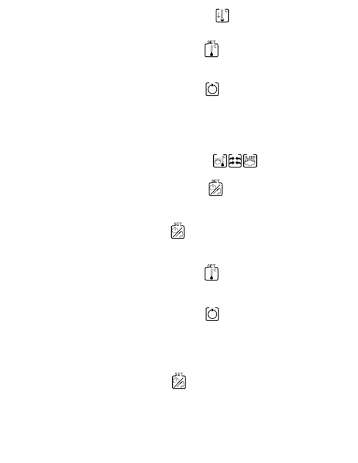
SELECT COMBINATION COOKING MODE BY TURNING THE MODE
SELECTION KNOB.
PRESS TEMPERATURE SET BUTTON AND WITH ADJUSTMENT
DIAL SELECT REQUIRED TEMPERATURE.(See item 3 on the control panel
key guide) (PRE-SET 0°C) (0 – 100°C)
PRESS START/STOP CYCLE BUTTON TO START
COOKING WITH CORE PROBE
CONNECT PROBE TO THE SOCKET LOCATED AT FRONT RIGHT
CORNER UNDER CONTROL PANEL
SELECT THE DESIRED COOKING MODE
PRESS AND HOLD TIME SET BUTTON FOR 5 SECONDS. DISPLAY
(NUMBER 1) WILL SHOW ACTUAL TEMPERATURE OF PROBE AND
PROBE INDICATOR LIGHT WILL ILLUMINATE.
PRESS TIME SET BUTTON AGAIN TO SET TEMPERATURE PROBE.
(PRE-SET AT 100°C) WITH ADJUSTMENT DIAL SELECT REQUIRED
TEMPERATURE.(See item 3 on the control panel key guide) (20 – 270°C)
PRESS TEMPERATURE SET BUTTON AND WITH ADJUSTMENT
DIAL SELECT REQUIRED TEMPERATURE.(See item 3 on the control panel
key guide) (PRE-SET 250°C) (20 – 270°C)
PRESS START/STOP CYCLE BUTTON TO START
WHEN THE PRE-SET CORE TEMPERATURE IS REACHED THE OVEN
WILL SWITCH OFF COOKING MODE.
BEFORE REMOVING THE PROBE FROM THE SOCKET, PRESS AND
HOLD TIME SET BUTTON FOR 5 SECONDS. PROBE INDICATOR
LIGHT WILL TURN OFF AND DISPLAY WILL SHOW “P” OR PRESET TIME
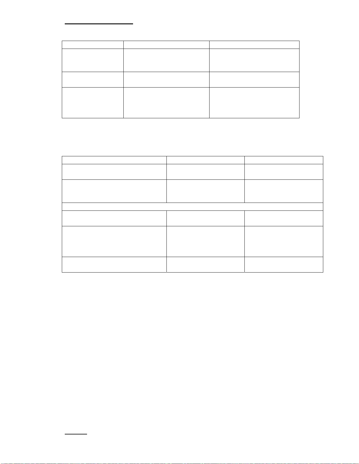
TECHNICAL DATA
KME 6 KME 10
VOLTAGES SINGLE 230v AC
3 PHASE 400v AC SINGLE 230v AC
3 PHASE 400v AC
CAPACITY 6.7KW 13.4KW
AMPS SINGLE 30 NOMINAL
3 PHASE 5.6 NOMINAL
PER PHASE
SINGLE 59 NOMINAL
3 PHASE 11.2 NOMINAL
PER PHASE
KME 6 KME 10
WATER OUTLET PRESSURE 2 bar min 10 bar max 2 bar min 10 bar max
WATER CONNECTION
Inlet (1) For Cooling
Inlet (2) For Steam Injection
2 x ¾ 2 x ¾
Unit comes complete with 2 hoses + Y connector for use on one water supply
DRAIN (3) 32mm 32mm
DIMENSIONS Dim A
Dim B
Dim C
900
770
778
900
1220
778
WEIGHT 90 Kg 125 Kg
KME 6
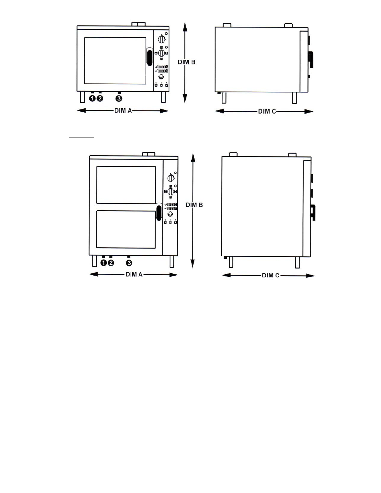
KME 10


This manual suits for next models
2
Table of contents
Other First Choice Oven manuals


