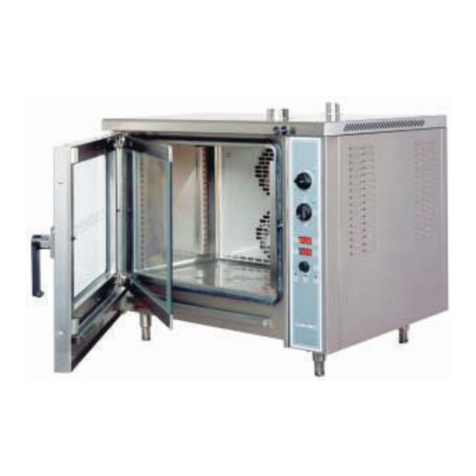
First Choice T2 Polis MC18 User manual

SPARE PARTS DIAGRAM FOR
First Choice Group
Blakeney Way, Kingswood Lakeside
Cannock, Staffs, WS11 8LD
TEL: 01543 577778 FAX: 01543504141
Email: [email protected]
Web: www.firstchoice-cs.co.uk
Bakery Oven
T2 Polis MC18
T3 Polis MC18
T4 Polis MC18
T6 Polis MC18

1
INDEX
1. INTRODUCTION.................................................................3
2. HOW TO USE THIS MANUAL.......................................4
3. SPECIFICATIONS..............................................................6
3.1. Identification of the product...................................................................6
3.2. Conformity to directives........................................................................6
3.3.Envisaged use.......................................................................................6
3.4.Technical specifications.........................................................................8
4. INSTALLATION WARNINGS..........................................9
4.1. Delivery checks.....................................................................................9
4.2. Choice of place of installation.............................................................10
4.3. Electrical connection...........................................................................10
5. INSTALLATION..................................................................12
5.1. Check list............................................................................................12
5.2. Choice of the place of installation of the oven....................................12
5.3. Moving the module .............................................................................12
5.4. Mounting the module..........................................................................13
5.5. Connecting the steam outlet...............................................................13
5.6. Checks before start up........................................................................15
6. CONTROL PANEL............................................................16
6.1 DESCRIPTION OF CONTROLS .........................................................16
7. FUNCTIONS.......................................................................17
7.1. SYSTEM FUNCTIONAL STATES......................................................17
7.1.1. Standby on/off button ...............................................................17
7.2. SETTINGS..........................................................................................17
7.2.1. Set temperature setting .......................................................17
7.2.2. Upper and lower element setting ..............................................17
7.2.3. Economy button........................................................................18
7.2.4. Start/Stop button........................................................................18
7.2.5. Oven light button ......................................................................19
7.2.6 Light switch for suction hood - Light switch for steam generator
................................................................................................................19
7.3. PROGRAMMING................................................................................19
7.3.1. Clock and day setting....................................................................19
7.3.2. Baking cycle programming............................................................20
7.3.3. Auto switch-on programming ........................................................21
7.3.4. Timer setting .................................................................................22

2
7.4. ALARMS.............................................................................................23
7.4.1. OVERTEMPERATURE ALARM....................................................23
8. THE USE OF THE OVEN..............................................24
8.1. Preparations for use ...........................................................................24
8.2. Switching on the control panel............................................................24
8.3. Settings...............................................................................................24
8.4. Starting baking....................................................................................24
8.5. Loading the oven................................................................................25
8.6. PROGRAMMING................................................................................25
8.6.1. Programming the clock .................................................................25
8.6.2.Programming temperature setting..................................................26
8.6.3. Programming on time for the oven roof and bedplate resistors....26
8.6.4. Programmed switching..................................................................26
8.7. General indications for good baking...................................................27
8.8. Switching off .......................................................................................29
8.9.Cleaning...............................................................................................29
9. CLEANING...........................................................................30
9.1. Cleaning of any visible glass and stainless steel parts.......................30
9.2. Cleaning of any refractory part ...........................................................30
9.3. Cleaning the oven’s baking chamber..................................................31
9.4. Cleaning the external surface.............................................................31
10. MAINTENANCE..............................................................32
10.1. ORDINARY MAINTENANCE WORK................................................32
10.1.1. Light replacement........................................................................32
10.2. Electrical diagram.............................................................................33
10.3. Adjustment for different feed voltages..............................................33
10.3.1. The cabling for the resistor wires................................................33
10.3.2. The cabling for the feed to the control panel...............................33
10.3.3. Application of new label ..............................................................34
10.4. Exploded views and spare parts list .................................................34
11. DECOMMISSIONING AND DEMOLITION...........41

3
1. INTRODUCTION
The modular “TEOREMA POLIS” ovens represent the new way of
making traditional pastry ovens.
They are designed and manufactured to demanding mechanical
and electrical standards and are built to last.
“TEOREMA POLIS” has been designed having in mind the end
user.
“TEOREMA POLIS” has a complete range to satisfy
everybody’s needs.
Dr. Zanolli S.r.l. thank you for the preference given to our company.
We at Zanolli can assure you that you have made a good choice as
we have been making quality products for decades now and have
never engaged in counterproductive penny-pinching in our selection
of the best available materials.

4
2. HOW TO USE THIS MANUAL
This manual should be kept near to the equipment itself so that
it can be quickly and easily consulted. The manual must travel with
the equipment if it is moved to another owner, as the latter may not
be considered complete or safe without it.
Please take note of the code and revision numbers which are
behind the back cover. If this copy should get mislaid or destroyed,
you can order another one by referring to the codes.
This manual is divided up into a number of chapters. All of
these should be read by the installers, maintenance staff and the
final user, both in relation to its safe use and in order to obtain the
best results from this product.
Despite this we also give below some useful indications on how to
look things up quickly in the various chapters.
The paragraphs with this symbol contain essential safety
information. They must all be read both by the installers and by
the final user and any of his staff who may use equipment. Dr.
Zanolli S.r.l. shall not be held liable for any damage which may
occur as a result of failure to observe the norms indicated in
these paragraphs.
The paragraphs with this symbol contain important information
which can be used to avoid damage caused to the equipment .
It is the user’s own interest also to read these paragraphs
carefully.
Chapter 3 describes the field of use of the equipment and provides
the characteristics and figures which may be needed when
choosing, installing and using it. It should be used as a reference to
check the use which is intended to be made of the equipment

5
corresponds to that for which it was designed, and whenever is
necessary, to know an exact size value relating to the equipment.
Chapter 4 and 5 provide all the information necessary for the
installation of the equipment. The manual is primarily written for
specialised staff but may be read in advance also by the final user
to prepare and set up the space and necessary for the proper
working of the equipment.
Chapter 6 is for reference when the user wishes to clarify specific
aspects of the control panel . It is not advisable to use this chapter
as a way to learn how to use the equipment from scratch.
Chapter 7 is useful for the user who has to learn to use the oven. It
guides the user through essential operations for switching on, use
and switching off of the equipment in safety. To exploit all of the
possibilities of the equipment the user should refer to chapter 6.
Chapter 8 provides all the information required for the cleaning of
the equipment i.e. all those operations which have to be carried out
by the user in order to ensure that the equipment continues to
function safely ( especially from the point of view of hygiene ) and
generally obtains the best result at all times.
Chapter 9 provides the information necessary for proper periodic
and extraordinary maintenance, e.g. repairing or replacing parts of
the equipment.
This chapter also has an exploded view of the equipment and list of
spare parts to make ordering and replacing any damaged part
easier.
These maintenance operations must be carried out by
specialised staff.

6
3. SPECIFICATIONS
3.1. Identification of the product
This is the manual for the following baking modules from the
Teorema Polis series:
T2 POLIS/MC18, T2 POLIS/MC28,
T3 POLIS/MC18, T3 POLIS/MC28,
T4 POLIS/MC18, T4 POLIS/MC28,
T6 POLIS/MC18 and T6 POLIS/MC28
3.2. Conformity to directives
The following baking modules:
T2 POLIS/MC18, T2 POLIS/MC28,
T3 POLIS/MC18, T3 POLIS/MC28,
T4 POLIS/MC18, T4 POLIS/MC28,
T6 POLIS/MC18 and T6 POLIS/MC28
bear the following compulsory mark:
which guarantees their conformity to the following European
directives:
- 89/336 CEE electromagnetic compatibility
- 73/23 CEE low voltage
3.3.Envisaged use
The following baking modules:
T2 POLIS/MC18, T2 POLIS/MC28,
T3 POLIS/MC18, T3 POLIS/MC28,
T4 POLIS/MC18, T4 POLIS/MC28,
T6 POLIS/MC18 and T6 POLIS/MC28
have been designed to bake pastry products.

7
The baking modules:
T2 POLIS/MC18, T2 POLIS/MC28,
T3 POLIS/MC18, T3 POLIS/MC28,
T4 POLIS/MC18, T4 POLIS/MC28,
T6 POLIS/MC18 and T6 POLIS/MC28
are intended for professional use in the food industry and are
exclusively intended to be used by qualified staff.
The operations envisaged in normal usage are the opening and
closing of the doors, the loading and unloading of the products from
the bedplates of the baking chamber, switching on, regulation,
switching off and cleaning of the equipment.

8
3.4.Technical specifications
The following table shows the baking modules’ technical
specifications
T2
POLIS
MC18
(MC28)
T3
POLIS
MC18
(MC28)
T4
POLIS
MC18
(MC28)
T6
POLIS
MC18
(MC28)
Units of
measure
-ment
Weight Kg
External dimensions 34x125x87
(46x125x87) 34x166x87
(46x166x87) 34x125x147
(46x125x147) 34x166x147
(46x166x147) cm
Baking chamber size 18x83x66
(28x83x66) 18x124x66
(28x124x66) 18x83x126
(28x83x126) 18x124x126
(28x124x126) cm
Number of 60x40
baking sheets 2 3 4 6 n°
Electrical feed three-phase or three-phase + neutral
Voltage 230 or 400 Vac
Frequency 50 or 60 Hz
Current at 400V 50Hz 8.7 11.3 14.5 18.8 A
Current at 230V 50Hz 15 19.6 25.1 32.7 A
Maximum instantaneous
current at 400 V 9.1 11.8 17.4 22.6 A
Maximum instantaneous
current at 230 V 15.7 20.5 30.1 39.3 A
Total electrical power 6 7.8 10 13 KW
Electrical connection plugless 4 or 5 lead cable
Cable length 2 M
Section of lead wires 4 6 (400V) 10 (230V) Mm2
Baking chamber light
Type halogen
Power 50 W
Baking control
Temperature control electronic thermoregulator
Maximum temperature
which can be set 370 °C
Thermostat safety
temperature 400 °C
Power control separate for oven roof and bedplate
Ambient conditions
Temperature 0 - 40 °C
Maximum humidity 95% without condensation

9
4. INSTALLATION WARNINGS
WARNING: These installation instructions are intended
only for staff which is qualified for the installation and the
maintenance of electrical and/or gas plant.
Installation by any other person may cause damage to the
equipment, persons, animals or things.
Furthermore, if it is necessary to make any modifications or
additions to the electrical and/or gas plant, where the equipment is
going to be installed, the person carrying out such alterations must
obtain certification that the works have been carried out in
accordance with the norms in force in that country.
4.1. Delivery checks
Unless otherwise agreed the products are carefully packed in a
strong wooden crate with a blister sheet of nylon to protect them
from shocks and humidity during forwarding and are delivered to the
driver in perfect conditions.
We recommend, however, that packaging is checked on arrival of
the goods, to ensure that there are no visible signs of damage. If
there are any such signs, indicate their nature on the delivery note,
which has to be signed by the driver.
Once the equipment is unpacked, check to see if it has suffered any
damage. Also check that any parts which are delivered unattached
to the equipment are present. If there has been any damage to the
equipment and/or any parts are missing, do not forget that the
forwarding company will accept complaints only up to 15 days from
the delivery day and that dr. Zanolli S.r.l. will not be liable for
damage suffered to its products during transport. We are
nevertheless willing to help you in presenting your complaint.

10
If there is any damage do not attempt to use the equipment
and call upon professionally qualified staff.
4.2. Choice of place of installation
The good, safe and long working of the equipment also depends on
the place where it is installed, so it is advisable to carefully evaluate
this before it is delivered. Install the equipment in a dry place which
is easily accessible both as regards its use and its cleaning and
maintenance. The area around the equipment must be free of
encumbrances. In particular it is necessary to avoid obstructions to
the cooling apertures. (Figure 15)
The equipment must in any case be installed at least 20 cm from
the walls of the room and from other equipment.
Finally, it is necessary to ensure that the temperature and
relative humidity of the place in which the equipment is installed
must never exceed the maximum and minimum values indicated in
the characteristics section (see 3.). In particular, if the maximum
temperature and relative humidity are exceeded, the equipment
may easily and unpredictably go out of order or be damaged in its
electrical parts, thus creating a dangerous situation.
4.3. Electrical connection
Zanolli equipment are supplied with a cable for the electrical
connection with earth lead. In observance of the current safety
norms it is compulsory to connect the earth wire (yellow-
green) to an equipotential system, whose efficiency must
be properly checked against the norms currently in force.
Before making any connections ensure that the characteristics
of the mains supply to which the equipment has to be
connected correspond to the feed characteristics required by
the equipment itself (see 3 and plate on equipment).

11
See (1) figure 5-3 for the exact position of the feed cable
output.
The feel cable must end in a plug, which connects to an electrical
feed panel with a corresponding socket and a differential magneto-
thermal switch.
The plug-socket connection must be such that the earth is
connected first and disconnected last and must be of the correct
size for nominal current (see 3).
Suitable plugs and sockets are the industrial type CEE 17 of any
which satisfy the European Norm EN 60309.
The terminal safety device must be set for total nominal current, the
magnetic safety device must be set for the instantaneous maximum
current (in the case of ovens it is a little above the nominal figure, in
the case of machines it is the pick up current for the most powerful
motor), while the different device must be set to the 30 mA current
(see3).
dr. Zanolli S.r.l. shall not be liable for any damage which results
from failure to observe the above mentioned norms.

12
5. INSTALLATION
5.1. Check list
There are no separately supplied parts.
5.2. Choice of the place of installation of the oven
Avoid obstructions to the cooling openings located on the right side
of the module (Figure
5.1).
In choosing the place
to install the baking
modules
T2 POLIS/MC18,
T2 POLIS/MC28,
T3 POLIS/MC18,
T3 POLIS/MC28,
T4 POLIS/MC18,
T4 POLIS/MC28,
T6 POLIS/MC18,and T6 POLIS/MC28 bear in mind that they might
to be completed with the addition of other modules or accessories
from the series (hood, proofer and so on).
5.3. Moving the module
When unloading and moving the
module when it is packed, use a fork-
lift or transpallet which has a capacity
at least equal to the weight of the
module, and insert the forks into the
space provided in the lower part of the
packing.
Fi
g
. 5.1 - Coolin
g
o
p
enin
g
s
Fig. 5.2 - Centre of gravity

13
When moving a module which is not packed, insert the forks in the
upper chamber.
It is also possible to transport the module by means of the two
hooks which are accessible from the openings in the top part.
In any case, to avoid unforeseen movements, take note of the
position of the centre of gravity (Figure 5.2 and table 5.1).
Table 5.1 - Centres of gravity
In addition, to avoid damage to the module, insert some
protective material between the forks and the module itself.
5.4. Mounting the module
Put the modules one above the other one in the right order (proofer
or base, baking module, hood) and fix by means of the supplied
hooks and screws.
5.5. Connecting the steam outlet
The steam outlet should be connected through the duct on the hood
(see instructions).
Avoid long horizontal stretches, as they may cause
accumulation of condensation and possible dripping.
a cm b cm c cm
T2 MC 18 70 42 17
T2 MC 28 70 42 23
T3 MC 18 90 42 17
T3 MC 28 90 42 23
T4 MC 18 70 74 17
T4 MC 28 70 74 23
T6 MC 18 90 74 17
T6 MC 28 90 74 23

14
Do not connect extractors, as they could cause a too low
pressure which would end up, removing heat from the cooking
chambers, even with the valves completely closed.
For the exact connection position see Figure 5.3.
Fig. 5.3 - Position of electrical cable input, steam outlet and plate

15
a cm h cm w cm
T2MC18 56 34 125
T2MC28 56 46 125
T3MC18 76 34 166
T3MC28 76 46 166
T4MC18 56 34 125
T4MC28 56 46 125
T6MC18 76 34 166
T6MC28 76 46 166
5.6. Checks before start up
Turn on the main switchboard.
Turn on the (1/0) switch , program a temperature over 200°C , set
both the power regulators at 9 and turn on the (Start/stop)
switch.
Check that the current to each phase is that indicated in chapter 3 ,
for the corresponding feed voltage.
Set the both power regulators at 5 and check that their lights go
on and off at intervals.
Turn off the switches (start/stop) and and the main switch,
placed on the switchboard.

16
6. CONTROL PANEL
6.1 DESCRIPTION OF
CONTROLS
Fig.6.1 shows the control panel
with all controls:
General system on/off button
Oven temperature and
time display
Set temperature display
Program setting increase
button
“Timer” - “Oven temperature” –
Clock setting” display button -
Program setting decrease
button
Upper element power setting
indicator
Upper element control display
Upper element power
sequential increase button
Lower element power setting
indicator
Lower element control display
Lower element power
sequential decrease button
Timer programming button
Baking cycle display
Baking cycle increase button
Oven light on/off
Baking start/stop button
Economy button
Light switch for suction
hood
Fig. 6.1 Control panelFig. 6.1 Control panelFig. 6.1 Control panel

17
7. FUNCTIONS
7.1. SYSTEM FUNCTIONAL STATES
7.1.1. Standby on/off button
When on standby the panel is powered but no system function is
enabled. The general remote switch is disabled and the message OFF
is displayed on the set display on the control panel along with the
current time on the display with flashing seconds dot (between
the second and third figure, ½ second on, ½ second off).
All buttons on the panel are disabled except for the button (system
on) and the key, pressure on which will bring the system to clock
setting mode (see “programming” section).
Pressing the button, the system comes on, the last SET temperature
programmed is displayed on the set display , and the cycle used
prior to switching the oven off is displayed on the display.
7.2. SETTINGS
7.2.1. Set temperature setting
To set the SET temperature use the and buttons until the desired
baking temperature appears on the display.
7.2.2. Upper and lower element setting
Pressing the buttons varies the time the oven heating elements
remain on. Each time the button is pressed increases this value by 1
unit, up to a maximum of 9 units. Further pressure returns the value to
0.
NB. Each unit on the two displays corresponds to 5 seconds element on
time. For the remaining units the elements remain off. The total duration
of the cycle is 45 seconds.

18
The on time of the two elements can be varied at any time, even during
the baking cycle. The upper elements during the first part of the cycle
while the lower ones come on during the second.
For example, setting the upper elements to 6 and the lower ones to 5
gives the following result:
5 10 15 20 25 30 35 40 45
Upper ON OFF
Lower OFF ON
Note that with this setting, for the first 20 seconds only the upper
elements are on, so the oven uses half the total power. Over the next
10 seconds both the upper and power elements are on, with the oven
using full power. In the remaining 15 seconds, on the lower elements
are on, so the oven once again uses half its available power.
7.2.3. Economy button
Pressing the economy button sets power values to pre-set levels
(upper 5 and lower 3) with the following result:
5 10 15 20 25 30 35 40 45
Upper ON OFF
Lower OFF ON
Note that with this setting, in the first 25 seconds only the upper
elements are on, with the oven using half power. Both elements are off
for the following 5 seconds. In the remaining 15 seconds only the lower
elements are on and so the oven once again uses only half power. This
means that throughout the cycle the oven never uses more than half
power and for 5 seconds power consumption is zero.
A similar result can be obtained through manual power settings, if the
sum of upper and lower times is less than or at most equal to 9.
7.2.4. Start/Stop button
Pressing the start/stop button starts the baking cycle according to the
previous setting.

19
7.2.5. Oven light button
Pressing the oven light button switches on the light in the oven.
Press again to switch it off.
7.2.6 Light switch for suction hood - Light switch for steam
generator
The light switch for suction hood control
is placed on the side part of the control
panel, on the upper side (Pos.1 of Fig. 7.1).
Push this switch on position 1 to start the
suction hood. Push this switch on position 0
to stop it.
Always on the side part of the control panel,
but at the bottom, you find the light switch
that starts and stops the steam generator,
if the oven is equipped with this accessory (see Pos.2 –Fig. 7.1).
7.3. PROGRAMMING
7.3.1. Clock and day setting
The time and day can only be set with the system on standby, that is to
say when the display “OFF”.
Pressing the key and holding it for 3 seconds displays the time on the
display with the two figures corresponding to the hour flashing.
The correct hour can be set using the and keys. To memorise the
new hour setting and pass on to setting minutes, press the key again.
The minutes start flashing and can be set in the same way as the hours.
Before pressing again, set the day of the week using the upper
element power sequence button . This displays the number
corresponding to the day on the upper element control display .
Pos.1
Pos.2
Fig 7.1
This manual suits for next models
3
Table of contents
Other First Choice Oven manuals
