First Choice Citizen 6 User manual

SPARE PARTS DIAGRAM FOR
First Choice Group
Blakeney Way, Kingswood Lakeside
Cannock, Staffs, WS11 8LD
TEL: 01543 577778 FAX: 01543504141
Email: [email protected]
Web: www.firstchoice-cs.co.uk
Oven Range
Citizen 6
Citizen 9

CONTENTS
Citizen gas 6 and 9 1
CONTENTS
1. PRESENTATION....................................................................................4
2. HOW TO USE THIS MANUAL ...............................................................5
3. FEATURES.............................................................................................7
3.1 PRODUCT IDENTIFICATION.............................................................7
3.2 COMPLIANCE WITH STANDARDS...................................................7
3.3 INTENDED USE..................................................................................7
3.4 TECHNICAL SPECIFICATIONS.........................................................7
4. INSTALLATION RECOMMENDATIONS..............................................11
4.1 DELIVERY CHECK...........................................................................11
5. INSTALLATION....................................................................................12
5.1 GAS CONNECTION..........................................................................12
5.2 SUPPLY LINE...................................................................................12
5.3 MAINS POWER CONNECTION .......................................................13
6. GENERAL FUNCTION.........................................................................15
6.1 FUNCTION: GENERAL PART..........................................................15
6.1.1 .Illuminated ON/OFF general switch ........................................15
6.1.2 Baking Start switch ........................................................................15
6.1.3 Oven temperature display .....................................................15
6.1.4 Set button...............................................................................15
6.1.5 and buttons .....................................................................16
6.1.6 Out indicator.....................................................................16
6.2 ERROR MESSAGES ........................................................................16
6.2.1 Thermocouple short-circuit ............................................................16
6.2.2 Disconnected thermocouple ..........................................................16

CONTENTS
Citizen gas 6 and 9
2
7. OPERATION........................................................................................ 17
7.1 DESCRIPTION OF CONTROLS ...................................................... 17
7.1.1 Temperature control...................................................................... 17
7.1.2 General ......................................................................................... 17
7.1.3 Flame control ................................................................................ 17
7.2 GENERAL SWITCH......................................................................... 18
7.3 THERMOSTATIC CONTROL........................................................... 18
7.4 BURNER ENABLE........................................................................... 18
7.5 FLAME CONTROL........................................................................... 19
7.6 MINIMUM/MAXIMUM SWITCH........................................................ 19
7.7 ACCIDENTAL FLAME-OUT ............................................................ 19
8. USE...................................................................................................... 20
8.1 FIRST IGNITION............................................................................... 20
8.2 GENERAL INDICATIONS FOR BAKING ........................................ 20
8.3 IF THE OVEN IS USED LITTLE....................................................... 21
8.4 SWITCHING THE OVEN OFF.......................................................... 21
9. CLEANING........................................................................................... 22
9.1 CLEANING REMOVABLE PARTS.................................................. 22
9.2 OVEN INTERIOR CLEANING.......................................................... 22
9.3 CLEANING EXTERNAL SURFACES.............................................. 22
10. MAINTENANCE ............................................................................... 24
10.1 ERROR MESSAGES........................................................................ 24
10.2 SAFETY THERMOSTAT.................................................................. 24
10.3 ELECTRICAL CIRCUIT DIAGRAM.................................................. 24
10.4 CONVERTING TO DIFFERENT TYPES OF GAS ........................... 26
10.4.1 Changing burner jets................................................................. 26

CONTENTS
Citizen gas 6 and 9 3
10.4.2 Minimum flame adjustment ........................................................26
10.4.3 Applying a new label ..................................................................27
10.5 EXPLODED VIEWS AND PARTS LIST............................................28
11. .DECOMMISSIONING AND DEMOLITION.......................................33

PRESENTATION
Citizen gas 6 and 9
4
1.PRESENTATION
The gas cooking units for modular ovens of the CITIZEN series are
designed principally for baking pizzas and similar products in a traditional
way.
Being part of the CITIZEN modular series, they can be coupled together and
with other elements of the series (Hood, Raising chamber, Base, Basic
modules) to meet the specific requirements of any customer. Versions are
currently available with 6 pizza and 9 pizza (Ø30 cm) oven trays.
The CITIZEN series gas units solve energy problems for users in zones were
high electrical current levels are not readily available. Gas burners also offer
substantial savings on running costs, reducing them in some cases to 60% of
those of an equivalent electric oven.
dr. Zanolli s.r.l. thanks you for the preference shown in choosing this oven.
We from Zanolli confidently guarantee that you have made a good choice,
backed by the experience of our company that has been producing quality
products for decades, using only the highest quality materials.

HOW TO USE THIS MANUAL
Citizen gas 6 and 9 5
2. HOW TO USE THIS MANUAL
Paragraphs marked with this symbol contain information
fundamental for safety. These sections must be read by installation
technicians, by the end user and employees of the same destined to
operate the oven. Dr. Zanolli s.r.l. declines all responsibility for
damages caused by failure to observe the norms given in these
paragraphs.
Paragraphs marked with this symbol contain important information
for preventing actions with could damage the oven. It is in the user’s
interest to read these paragraphs carefully.
This manual should be kept in good condition and stored in an easily
accessible place near to the oven, where it can be immediately consulted. In
the event of transfer or sale, the manual must accompany the oven as it
cannot be considered complete without it.
Take note of the manual code and revision number indicated on the inside
of the cover. If this copy is lost or destroyed, you can order another one by
quoting these numbers.
This manual is subdivided into various chapters. All of them should be
read by maintenance technicians and by the end user, both for safety
reasons and in order to obtain the best results from this product.
Assuming the manual will be read in its entirety, the following is a brief
guide to each of the chapters to facilitate rapid consultation.
Chapter 3 gives details of oven features and all data and settings relative
to its installation and use.
It should be used as a reference to check whether the use intended for the
equipment corresponds to those envisaged by the manufacturer, and any
time the exact value of any given quantity relative to the equipment needs to
be known.

HOW TO USE THIS MANUAL
Citizen gas 6 and 9
6
Chapters 4 and 5 contain all the information necessary for installing the
oven. This is mainly addressed to specialised personnel, but should also be
read in advance by the end user, for the preparation of the space and
services necessary for operating the oven.
Chapters 6 and 7 serve as reference whenever the already expert oven
operator, needs to clarify certain specific aspects of its operation .
It is not advisable to use these chapters when learning to use the
machine from scratch.
Chapter 8 is dedicated to users having to learn to use the oven from
scratch. It guides the user through all indispensable operations regarding
switching on, operating and switching off the oven in conditions of complete
safety. To take advantage of all the possibilities the oven offers, the user
should then refer to chapters 6 and 7.
Chapter 9 provides all the information necessary for cleaning the oven,
meaning all the operations which should be performed by the operator in
order to guarantee that the oven continues to operate in completely safe
conditions (above all in terms of hygiene) and in any case to obtain the best
results from it.
Chapter 10 gives all necessary information for periodic and special
maintenance, including the repair and replace of parts of the oven. This same
chapter also contains exploded views of the oven and a complete list of its
component parts, to facilitate ordering and replacing any damaged parts.
These maintenance operations must be performed by qualified
maintenance personnel.

FEATURES
Citizen gas 6 and 9 7
3.FEATURES
3.1 PRODUCT IDENTIFICATION
These instructions are for Citizen 6 gas and Citizen 9 gas cooking units.
3.2 COMPLIANCE WITH STANDARDS
Citizen 6 gas and Citizen 9 gas cooking units both bear the following
obligatory markings:
49.AR.1710 indicating that they comply with the following European
directives:
90/396 CEE gas fired appliances
89/336 CEE electromagnetic compatibility
73/23 CEE low voltage
3.3 INTENDED USE
Citizen 6 gas and Citizen 9 gas cooking units are designed for baking
pizzas, or similar products, in the catering industry (restaurants, pizzerias,
etc. and are intended for professional use by trained personnel.
The operations envisaged during normal cooking unit use are: putting in
and taking out products from the oven, switching it on, regulating and
switching it off, in addition to general cleaning.
3.4 TECHNICAL SPECIFICATIONS
The following tables give all the technical specifications of the cooking
units.
For the Italian market, gas of category II2H3+ : G20 - 20 mbar e G30/G31 -
28..30/37 mbar may be used

FEATURES
Citizen gas 6 and 9
8
Citizen 6
GAS Citizen 9
GAS Units of
measure
Weight 160 300 Kg
External dimensions 970x1300x470 1270x1300x470 mm
Oven dimensions 650x950x175 950x950x175 mm
Power supply single phase
Voltage 230 Vac
Frequency 50 or 60 Hz
Current at 230 V 50 Hz 2 2 A
Total electrical power 100 100 W
Mains lead Three ply without plug
Lead length 2 m
Conductor section 1.5 mm2
Oven light
Type D50 300°C
Power 50 W
Burner type Atmospheric
Category AT II2H3B/P – DK SE FI CH II2H3B/P - BE I2E(R)B
CH ES GB IE IT PT II2H3+ - LU I2E - DE II2ELL3B/P-
GR BE I3+ - FR II2ER3+ - NO I3B/P - NL II2L3B/P
Jet diameter according to gas type and pressure
G20 - 20 mbar 3.85 mm
G25 - 20 mbar 3.85 mm
G25 - 25 mbar 3.85 mm
G30 - 28..30 mbar 2.1 mm
G31 - 37 mbar 2.1 mm
G30 - 50 mbar 1.9 mm
G31 - 50 mbar 1.9 mm
Primary air adjustment according to gas type and pressure
(given in mm from the fully closed position, see Fig. 10-2)
G20 - 20 mbar open mm
G25 - 20 mbar open mm
G25 - 25 mbar open mm
G30 - 28..30 mbar open mm
G31 - 37 mbar open mm
G30 - 50 mbar open mm
G31 - 50 mbar open mm
Pressure at jet according to gas type and supply pressure at rated
capacity
G20 – 20 mbar 8 mm
G25 – 20 mbar 13 mm

FEATURES
Citizen gas 6 and 9 9
G25 - 25 mbar 13 mm
G30 - 28..30 mbar - mm
G31 - 37 mbar - mm
G30 - 50 mbar - mm
G30 - 50 mbar - mm
Minimum pressure at jet according to gas type and supply pressure
G20 - 20 mbar 3.2 mm
G25 - 20 mbar 4.3 mm
G25 - 25 mbar 4.3 mm
G30 - 28..30 mbar 9 mm
G31 - 37 mbar 9 mm
G30 - 50 mbar 9 mm
G30 - 50 mbar 9 mm
Gas connection ISO 7 - (conical threaded gas)
pipe Ø 1/2”
Consumption
Max. burner power 17 KW
G20 capacity – 20 mbar 1.8 m3/h
G25 capacity – 25 mbar 2.1 m3/h
G30 capacity - 28..30 mbar 1.33 Kg/h
G30 capacity – 50 mbar 1.33 Kg/h
Minimum burner power 10 Kw
G20 capacity – 20 mbar 1.1 m3/h
G25 capacity – 25 mbar 1.2 m3/h
G30 capacity - 28..30 mbar 0.8 Kg/h
G30 capacity – 50 mbar 0.8 Kg/h
Flue
Type B11
Diameter 150 mm
Air change
34 m3/h
Flame control Electronic without pilot light
Safety time <5 s
Flame ignition spark
Baking control computerised electronic
Temperature units of
measure °C
Maximum settable
temperature 370 °C
°C
Flame intensity control automatic or manual
Error signals by display

FEATURES
Citizen gas 6 and 9
10
Ambient conditions
Temperature 0 - 40 °C
Maximum humidity 95% no dew point
Table 3-1 technical specifications

INSTALATION RECOMMENDATIONS
Citizen gas 6 and 9 11
4.INSTALLATION RECOMMENDATIONS
IMPORTANT: These installation instructions are intended for use
exclusively by qualified gas appliance installation and maintenance
personnel. Installation by unskilled personnel may result in damage to
the oven and injury to persons.
In addition, if modifications or extensions to existing electricity or gas
distribution systems in the building where the oven is installed, such works
must be certified.
4.1 DELIVERY CHECK
Unless otherwise agreed, the oven is carefully packed in a robust wooden
structure with a sheet of blister pack plastic to protect it from physical damage
and damp during transport, and handed over to the forwarder in the best
condition.
We therefore recommend that you check the packaging on delivery for any
sign of damage. If found, note any damage on the receipt, which must be
counter-signed by the driver.
Once the oven is unpacked, check whether it has suffered damage. Also
check that all parts indicated on packing lists are present,. In case of damage
to the oven and/or missing parts, note that the forwarder can accept
complaints only up to 15 days following delivery, and that dr. Zanolli s.r.l.
does not respond for damage to its products during transport. However, we
are able to assist in presenting your complaint.
In case of damage, do not attempt to use the oven, but call a qualified
professional technician.

INSTALLATION
Citizen gas 6 and 9
12
5. INSTALLATION
5.1 PLACE OF INSTALLATION
Efficient, safe and long operation of the machine also depends on the
place chosen for its installation, so it advisable to carefully evaluate where to
install it before it is delivered.
It should be installed in a dry place that is easily accessible for use,
cleaning and maintenance. The area surrounding the oven must be kept free
of obstructions. In particular, cooling and gas burner air intakes must not be
covered under any circumstances.
The oven must in any case be installed no less than 20 cm from walls or
other equipment.
Since it is a gas appliance, the place of installation must be adequately
ventilated.
There must be an aperture connected directly to the outside at floor level,
with a cross-sectional area of at least 6 cm2for each kW of max. power
developed by the burner, with a minimum of 100 cm2.
Lastly, you should check that the temperature and relative humidity in
the place of installation never exceeds the minimum and maximum values
given in specifications (not even during operation of the oven itself or other
equipment present) (see paragraph 3.4). Temperatures and relative humidity
in excess of these values could lead to unpredictable and hazardous damage
to electrical systems.
5.1 GAS CONNECTION
Before making any connection, check that the type and pressure of the
gas for which the oven has been calibrated (indicated on the initial settings
label on the ID plate) corresponds to the type and pressure of the gas
supplied to your premises. If these do not correspond, refer to chapter 10 for
changing settings.
5.2 SUPPLY LINE
INSTALLATION
Citizen gas 6 and 9 13
Gas appliances are fitted with a ½” conical threaded connector, as
indicated in specifications. Connections to the building’s gas mains must be
made in galvanised steel or copper piping, and must be inspectionable.
The oven must be connected to the gas supply through an easily
accessible cut-off valve.
The connection between gas piping and the oven must be made with a
three piece metal joint to facilitate dismantling.
Seals at the threads of all joints must be ensured by materials declared
suitable also for use with LPG.
5.3 MAINS POWER CONNECTION
Zanolli appliances are supplied with a mains lead with earth. IN
compliance with current safety standards, it is obligatory to connect the
earth wire (yellow-green) to an equipotential system, correctly tested
according to current standards.
Before making any electrical connections, check that the mains supply
corresponds to the power requirements of the oven (see Table 3-1).
For gas ovens without pilot light, when the 230 Vac required for the control
system is derived from a neutral/phase bridge (three-phase 400 Vac supply),
polarity must be respected, remembering that the blue wire is neutral and the
brown one live. Otherwise the flame sensor will not work, and the burner will
block (see chapter 7).
The mains lead must be fitted with a plug for connection to an electrical
panel with differential cut-out switch.
The plug-socket connection must be made such that the earth is connected
first and disconnected last as the plug is inserted and removed, and must be
suitably sized for the rated current see Table 3-1). We recommend CEE 17
type plugs and sockets for industrial use, or any others which comply with
European standard EN 60309.
The thermal cut-out switch in the panel must be calibrated to the total
current rating, and the magnetic safety must be calibrated to the maximum
instantaneous current rating (for ovens this is little higher than rated current,

INSTALLATION
Citizen gas 6 and 9
14
while for machines, pick-up current is much greater), whilst the differential
safety device must be calibrated to 30 mA (see table 3-1).
dr. Zanolli s.r.l. will not respond for damages caused by failure to respect
the above standards.

GENERAL FUNCTION
Citizen gas 6 and 9 15
6. GENERAL FUNCTION
6.1 FUNCTION: GENERAL PART
To locate the controls described below, refer to Fig 7-1, chapter 7.
6.1.1. Illuminated ON/OFF general switch
When this switch is OFF, all the indicators on the control panel are off.
When ON, the switch itself and the thermostatic control come on, so
temperature can be set. Oven heating is disabled while the switch is off.
6.1.2 Baking Start switch
With this switch in position O, the oven remains off, independent of set
temperature and power. Switching it to I, the switch itself lights up and the
oven begins to heat to the set temperature and power.
6.1.3 Oven temperature display
When programming, this display shows the programmed temperature.
The warning light to the side indicates when this temperature has been
reached. This display is also used for a number of error messages.
6.1.4 Set button
To enter temperature programming mode, press and immediately release
the button.
IMPORTANT! to not hold it down for more than 4 seconds, because
this will enter parameter programming mode, with possible modifications to
thermostatic control parameters and consequent unpredictable malfunction.
In this way, the display shows the programmed temperature that can
be modified using the and buttons. If no button is pressed for 3
seconds, the thermostatic control automatically returns to normal function.
For the range of temperatures that can be set, refer to chapter 8.

GENERAL FUNCTION
Citizen gas 6 and 9
16
6.1.5 and buttons
Pressing and releasing these buttons once, the set temperature
increases or decreases by one unit. Holding the buttons down allows
temperature settings to be increased or decreased progressively, at first
slowly, and then faster.
6.1.6 Out indicator
The indicator lights each time oven temperature falls below set
temperature. It goes out when the oven reaches set temperature and comes
back on if oven temperature falls to 1°C below set temperature.
When the is on, the oven elements come on at the respective
power settings.
6.2 ERROR MESSAGES
The electronic thermostatic control system also signals the malfunctions
described in the following paragraphs.
6.2.1 Thermocouple short-circuit
If the thermocouple is shorted, the display shows “---”.
6.2.2 Disconnected thermocouple
If the thermocouple is disconnected, the display shows “EEE”.
The same error code also appears if oven temperature exceeds the
maximum setable value.
OPERATION
Citizen gas 6 and 9 17
7. OPERATION
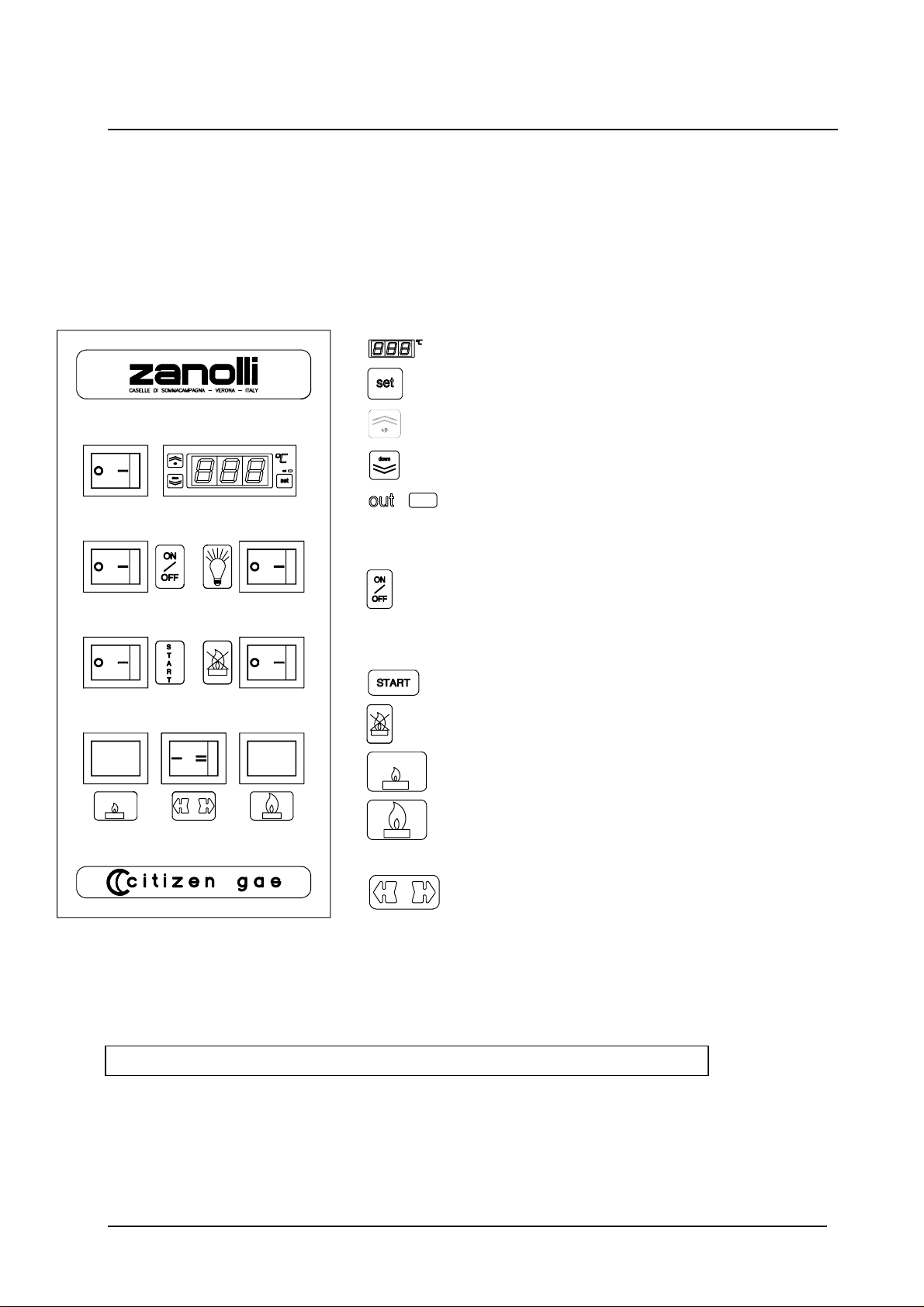
7.1 DESCRIPTION OF CONTROLS
7.1.1 Temperature control
Oven temperature display
Set button
Up button
Down button
Out indicator
7.1.2 General
Illuminated green general switch
7.1.3 Flame control
Illuminated burner enable switch
Illuminated red release button
Green minimum intensity indicator
Yellow maximum intensity
indicator
Minimum/maximum selector
Figure 7-1 shows the control panel with all controls

OPERATION
Citizen gas 6 and 9
18
7.2 GENERAL SWITCH
The general switch powers the thermostatic control and the rest of
the electrical panel.
Use of the switch could cause the burner to light. If this is to be
avoided, make sure the switch is OFF (see 6.1.1)
7.3 THERMOSTATIC CONTROL
The thermostatic control has a display, two buttons and a red LED.
The display indicates the effective oven temperature.
The two buttons (increase and decrease ) are for setting the desired
temperature at any time. Short pressure on either button increases or
decreases temperature n 1°C steps. Holding the button down progressively
increases or decreases temperature, slowly at first, then faster..
If on, the red LED indicates that the thermostatic control has activated the
burner to reach or maintain the set temperature.
IMPORTANT during this transition phase, the LED may come on
causing the burner to ignite. If this is to be avoided, before switching on at the
general switch, check that the switch is OFF.
Starting from a temperature effectively lower than set temperature, the
thermostatic control will continue to demand heat (red LED on) until the
effective oven temperature exceeds set temperature by 1°C. At this point the
red LED goes out, and the burner shifts to minimum, returning to maximum if
the effective temperature drops to 1°C below set temperature.
7.4 BURNER ENABLE
The burner enable switch serves to prevent burner ignition when
switching on the electrical panel and/or setting the various baking
parameters. In effect, if OFF, it impedes burner ignition in all circumstances. If
ON, the burner may ignite according to the set operating cycle. The switch
lights to indicate burner enabled.
IMPORTANT: for switching on, make sure that the
minimum/maximum selector is set to “maximum”.

OPERATION
Citizen gas 6 and 9 19
7.5 FLAME CONTROL
Electronic flame control is enabled at the start of the burner ignition cycle
once the thermostatic control activates (red LED on) and the switch is
ON.
Once the flame is stable, the control disables ignition and enables the
solenoid valve only if the minimum/maximum switch is set to maximum.
In this case, from stable the flame reaches maximum intensity.
7.6 MINIMUM/MAXIMUM SWITCH
The switch serves to selector flame intensity. Position “I”
corresponds to minimum intensity, and position “II” to maximum. The green
light indicates operation at minimum intensity, and the yellow light
indicates maximum intensity.
7.7ACCIDENTAL FLAME-OUT
If the flame goes out during normal operation (for example, due to gas
supply failure) the electronic control closes the solenoid valves and repeats
the entire ignition cycle.
This manual suits for next models
1
Table of contents
Other First Choice Oven manuals


