First Products ND-120 Installation and operation manual

OPERATOR’S
MANUAL & PARTS LIST
MULTI-drill
MODEL ND-120
FIRST PRODUCTS INC.
164 Oakridge Church Road
Tifton, Georgia 31794 U.S.A.
Phone (229) 382-4768
1-800-363-8780
Fax (229) 382-0506
Web: www.1stproducts.com Email: Sales@1stproducts.com
ND-120 SER. 1004 thru ___
Printed in U.S.A.
PBREV 0623

1
INTRODUCTION
Thank you for purchasing a First Products Multi-Drill. This piece of equipment has been carefully
engineered and manufactured to provide years of reliable service.
The Multi-Drill is one of the most unique and versatile pieces of equipment on the market today.
It is designed for primary seeding in various soil conditions.
We recommend that you carefully read the operators manual prior to operation. Also ensure that
all future operators read this manual and become fully trained before allowing them to use or
maintain this equipment. Time spent becoming acquainted with the safe operation, performance,
and maintenance of the Multi-Drill will add longer life and greater satisfaction to your new
purchase.
This machine is designed with safety in mind. However, if the machine is handled carelessly and
not as instructed, it can be a dangerous piece of equipment. Observe all safety information in this
manual and decals on the equipment.
The illustrations and data used in the manual were current at the time of printing. The manufacturer
reserves the right to make changes or add improvements to its products at any time without
incurring any obligation to make such changes to products manufactured previously.
For service questions, First Products has trained personnel, genuine First Products parts, and the
necessary tools/equipment to handle all your needs.
Use only genuine First Products parts. Substituting parts will void warranty and may not meet
standards required for safe and satisfactory operation. Record the model number and serial number
of your equipment in the spaces provided below:
MODEL: __________________________________
SERIAL NUMBER: _________________________
DATE OF PURCHASE: _____________________
Read and understand the instructions and warnings carefully before using
this machine.
Read the warranty located on page 18. Fill in the required information on
the warranty registration provided and return to the address on the front of
this manual. The warranty registration must be returned to validate
warranty.
REMEMBER SAFETY IS ALWAYS FIRST!

2
TABLE OF CONTENTS
INTRODUCTION ...................................... 1
TABLE OF CONTENTS ............................ 2
GENERAL INFORMATION ..................... 3
SPECIFICATIONS for ND-144 ................. 3
SAFETY SYMBOLS.................................. 4
SAFETY RULES ........................................ 5
Training ................................................... 5
Preparation .............................................. 5
Operation ................................................. 5
Transportation ......................................... 6
Maintenance ............................................ 6
Storage ..................................................... 7
SAFETY DECALS ..................................... 7
OPERATION .............................................. 9
Front Coulter Disc Shaft ....................... 10
Seed Disc Assembly .............................. 10
Seeders .................................................. 10
Attaching Multi-Drill ............................ 11
1. Standard Cat. II/III 3-point hitch: 11
2. Standard Cat. II Quick hitch: ....... 11
3. Tow hitch with hydraulics: ........... 11
Seeder Setup .......................................... 12
Seeder Controls ................................. 12
Setting Seed Depth ............................. 13
Seeder Calibration ............................. 14
CLEANING .............................................. 17
After Each Use ...................................... 17
Periodic or Before Extended Storage .... 17
WARRANTY INFORMATION .............. 18
Parts Book ................................................. 23
Row Unit Group .................................... 23
Spring Rod Group ................................. 27
Press Wheel Arm Group ....................... 28
Frame Group ......................................... 29
Coulter Shaft Group .............................. 33
Frame to Seeder Group ......................... 34
Primary Hopper Group .......................... 37
Primary Hopper (Rt) Group .................. 41
Agitator Group ...................................... 45
Spout Tray Group ................................ 467
Hydraulic Idler Group ......................... 478
Hydraulic Motor Group ....................... 489
Hopper Hydraulics Group ..................... 50
Auxiliary Hopper Group ....................... 52
Auxiliary Hopper (Rt) Group ................ 56
Auxiliary to Primary Hopper Group ..... 59
Chain Cover Group ............................... 60
Auxiliary Chain Cover Group ............... 61
Electrical Group .................................... 62
Tow Hitch Group .................................. 64

3
GENERAL INFORMATION
The purpose of this manual is to assist you in operating and maintaining your Multi-Drill. Read
it carefully. It furnishes information and istructions that will help you achieve years of
dependable performance. These instructions have been compiled from extensive field
experience and engineering data. Some information may be general in nature due to unknown
and variying operating conditions. However, through experience and these instructions, you
should be able to develp procedures suitable to your particular situation.
The illustrations and data used in this manual were current at the time of printing, but due to
possible inline production changes, your machine may vary slightly in detail. We reserve the
right to redesign and change the machines as may be necessary without notification.
Throughout this manual, references are made to right and left locations. These are determined
by standing behind the equipment facing the direction of forward travel.
SPECIFICATIONS for ND-144
Working Width 126”
Overall Width 162”
Disc Diamete
r
Coulter disc: 16” / Seed disc: 13.5”
Disc Spacing 9”
Hitch Cate
g
or
y
CAT II/III
Quick Hitch Compatible Yes
Hydraulic Lift Compatible No
Towin
g
Hitch Compatible Yes
Gua
g
e Wheels 32 X 11 X 15 (Implement Tire – 20 mph max)
Wei
g
ht w/ all options 4600 Lbs
Primar
y
Seedbox Capacit
y
16 Bushels
Auxiliary Seedbox Capcity 6 Bushels
Primar
y
Seed Distribution Metho
d
Gravit
y
metered into rows
Seed Depth Gau
g
e Metho
d
Gua
g
e Wheels
–
Turnbuckle
Warning
Multi-Drill should never be operated with any safety shielding removed.

4
SAFETY SYMBOLS
ATTENTION! BECOME ALERT! YOUR SAFETY IS INVOLVED!
This is a standard safety alert symbol meaning
CAUTION
Indicates hazardous situation, injury may
occur, used to alert against carelessness.
WARNING
Indicates potentially hazardous situation. Death
or serious injury may occur if proper
procedures are not followed.
DANGER
Indicates most hazardous situation. Death or
serious injury will occur if proper procedures
are not followed.

5
SAFETY RULES
Safety is a primary concern in the design and manufacturing of our products. However, our
efforts to provide safe equipment can be avoided by an operator’s careless act. Accident
prevention ultimately is dependent upon the awareness, concern, judgement, and proper training
of the personnel involved in the operation, transport, maintenance, and storage of the equipment.
It is incumbent upon every operator to practice proper safety protocol to avoid life-threatening
situations.
Training
Safety instructions are important! Read all
attachment and power unit manuals; follow
all safety rules and safety decal information.
Failure to follow instructions or safety rules
can result in serious injury or death.
If you do not understand any part of this
manual and need assistance, call First
Products.
Know your controls and how to stop engine
and attachment quickly in an emergency.
Operators must be instructed in and be
capable of the safe operation of the
equipment, its attachments, and all controls.
Do not allow anyone to operate this
equipment without proper instructions.
Never allow children or untrained persons to
operate equipment.
Preparation
Check that all hardware is properly installed.
Always tighten to torque chart specifications
unless instructed otherwise in this manual.
Always wear relatively tight and belted
clothing to avoid getting caught in moving
parts. Wear proper personal protective
equipment for eyes, hair, hands, hearing, and
head.
Make sure all safety decals are installed.
Replace if damaged. See Safety Decals
section for location and part numbers for
ordering replacements.
A minimum 20% of tractor and equipment
weight must be on the tractor’s front wheels
when attachments are in transport position.
Without this weight, front tractor wheels
could raise up and result in loss of steering.
Operation
Keep bystanders away from equipment.
Do not operate or transport equipment while
under the influence of alcohol or drugs.
Operate only in daylight or good artificial
light.
Keep hands, feet, hair, and clothing away
from equipment while engine is running.
Stay clear of all moving parts.
Always comply with all state and local
lighting and marking requirements.
Never allow riders on power unit or
attachment.
Power unit must be equipped with ROPS or
ROPS cab and seat belt. Keep seat belt
securely fastened. Falling off power unit
can result in death from being run over or
crushed. Keep foldable ROPS system in
“locked up” position at all times.
Always sit in power unit seat when
operating controls or starting engine.

6
Securely fasten seat belt, place transmission
in neutral, engage brake, and ensure all other
controls are disengaged before starting
power unit engine.
Look down and to the rear and make sure
area is clear before traveling in reverse.
Do not operate seeder in reverse.
Use extreme care when working close to
fences, ditches, other obstructions, or on
hillsides.
Do not operate or transport on steep slopes.
Do not start, stop, or change directions
suddenly on slopes.
Use extreme care and reduce ground speed
on slopes and rough terrain.
Watch for hidden hazards on the terrain
during operation.
Stop power unit and equipment immediately
upon striking an obstruction. Turn off
engine, remove key, inspect, and repair any
damage before resuming operation.
Transportation
Use additional caution and reduce speed
when under adverse surface conditions,
turning, or on inclines.
A minimum 20% of tractor and equipment
weight must be on the tractor’s front wheels
when attachments are in transport position.
Without this weight, front tractor wheels
could raise up and result in loss of steering.
The weight may be attained with front wheel
weights, ballast in tires, front tractor
weights, or front loader. Weigh the tractor
and equipment. Do not estimate.
Do not operate or transport on steep slopes.
Always raise unit and install transport lock
before transporting. Leak down or failure of
mechanical or hydraulic systems can cause
equipment to drop.
When utilizing a pull-type hitch, always
attach safety chain to tractor drawbar when
transporting unit.
Never exceed 20 mph (32.2 hm/h) during
transport.
Maintenance
Before dismounting power unit or
performing any service or maintenance,
follow these steps: 1) disengage power to
equipment 2) lower unit to ground 3)
operate valve levers to release any hydraulic
pressure 4) set parking brake 5) stop engine
6) remove key 7) unfasten seat belt.
NEVER GO UNDERNEATH
EQUIPMENT. Never place any part of the
body underneath equipment or between
moveable parts even when the engine has
been turned off. Hydraulic system leak-
down, hydraulic system failures, mechanical
failures, or movement of control levers can
cause equipment to drop or rotate
unexpectedly resulting in severe injury or
death. (Service work does not require going
underneath).
Read Operator’s Manual for service
instructions or have service performed by
qualified personnel.
Make sure attachment is properly secured,
adjusted, and in good operating condition.
Keep all persons away from operator control
area while performing adjustment, service,
or maintenance.
Tighten all bolts, nuts, and screws to torque
chart specifications. Check that all cotter
7
Figure 1. Safety Decal placement on Multi-Drill
pins are installed securely to ensure
equipment is in a safe condition before
putting unit into service.
Make sure all safety decals are installed.
Replace if damaged. See Safety Decals
section for location and corresponding part
numbers.
Storage
Block equipment securely for storage.
Cover with tarp included with seeder.
Keep children and bystanders away from
storage area.
SAFETY DECALS
Your implement comes equipped with all safety labels in place. They were designed to help you
safely operate your implement.
1. Read and follow decal directions.
2. Keep all safety decals clean and legible.
3. Replace all damaged or missing decals.
4. Refer to this section for proper decal placement.
Avoid spraying too close to decals when using a pressure washer; high pressure water can enter
through very small scratches or under edges of decals causing them to peel or come off.
To install new decals:
Clean the area the decal is to be placed. Peel backing from decal. Press firmly on surface being
careful not to cause air bubbles under label.

8
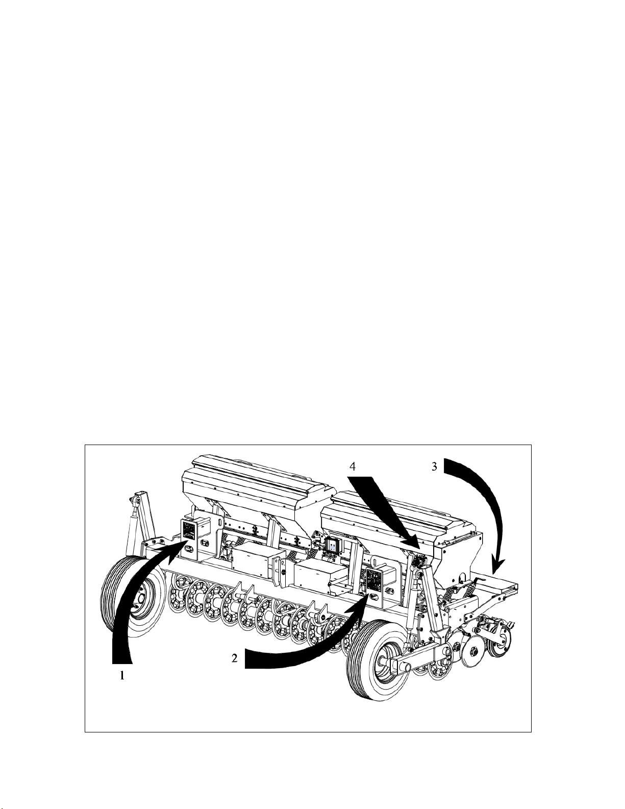
2 – Operator Warning (DS50-068)
3 – No Riders (AG50-089)
4 – Hydraulic Pressure (AE50-194)
1 – General Warning (DS50-067)

9
OPERATION
The operator is responsible for the safe operation of this seeder. The operator must be properly
trained. Operators should be familiar with the equipment, the tractor, and all safety practices
before starting operation. Read the safety rules and safety decals provided in this operator’s
manual.
The Multi-Drill is an excellent primary seeder, food plot seeder, and conservation seeder. Its
primary function is to deliver a variety of seed to the soil at the desired depth with minimal ground
disturbance. The Multi-Drill does this utilizing a series of discs to cut narrow slits in the ground
where seed is precisely positioned at the proper depth and packed down via closing wheels. The
Multi-Drill is capable of planting multiple seed varieties at once due to its optional second seed
box attachment. Seed plates are adjusted on the hoppers to achieve the desired seed rates while
electric actuators shuttle the hopper outlets open and closed. When the electric actuators open the
hopper outlets, a hydraulic motor powers an agitator shaft which stirs the seed over every outlet to
encourage the free flow of seed at the measured rate. The speed of the hydraulic motor can be
changed to finetune the seed rate.
WARNING
Power unit must be equipped with Roll Over Protection System (ROPS) or ROPS cab and
seat belt. Keep seat belt securely fastened. Falling off power unit can result in death from
being run over or crushed. Keep foldable ROPS system in” locked up” position at all times.
Never allow children or untrained persons to operate equipment.
Keep bystanders away from equipment.
Keep hands, feet, hair, and clothing away from equipment while engine is running. Stay clear
of all moving parts.
CAUTION
Stop power unit and equipment immediately upon striking an obstruction. Turn off engine,
set parking brake, remove key, inspect, and repair any damage before resuming operation.
Always wear relatively tight and belted clothing to avoid getting caught in moving parts.
Wear proper personal protective equipment for eyes, hair, hands, hearing, and head.
10
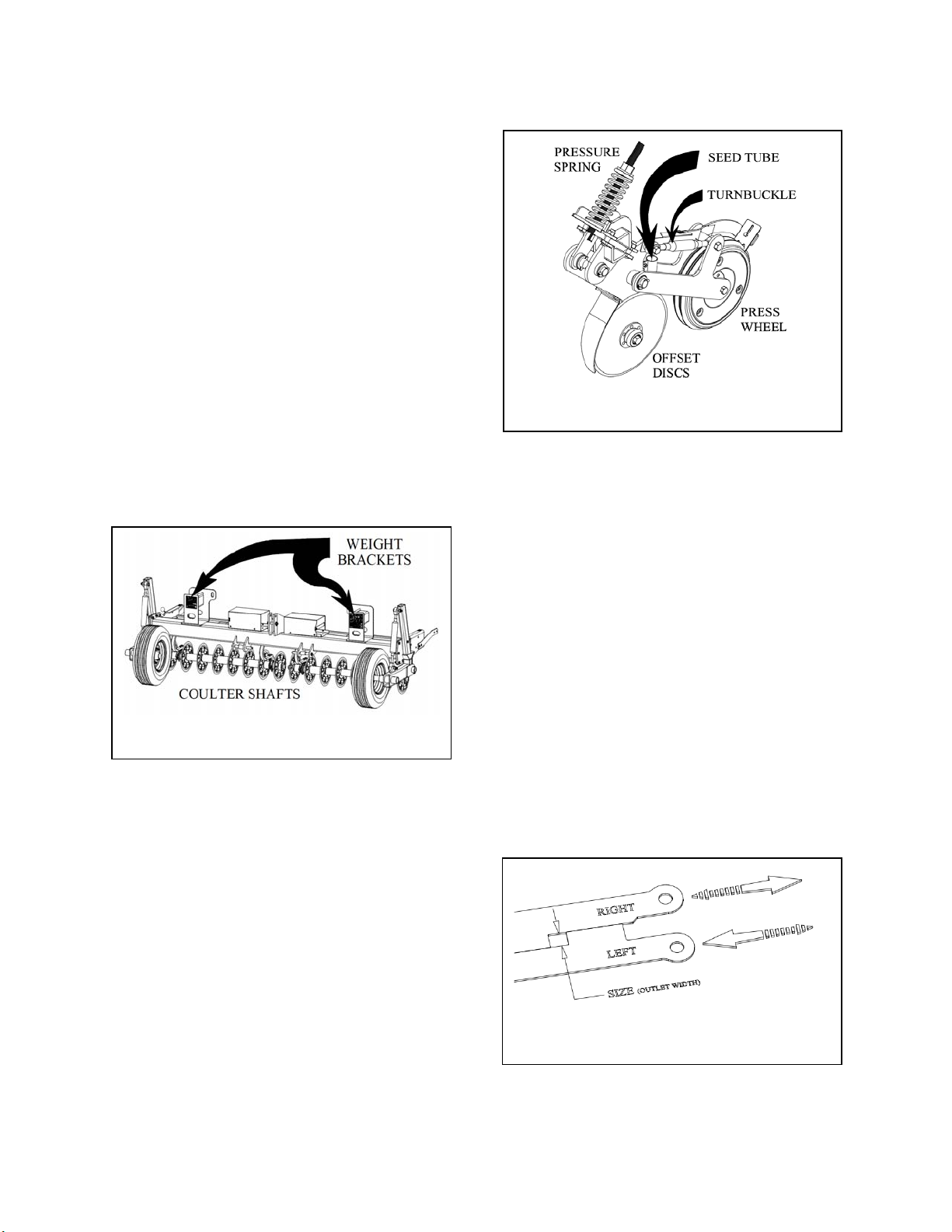
Front Coulter Disc Shaft
The Multi-Drill is equipped with a coulter
disc shaft mounted to the front of the frame.
The function of this shaft is to cut a narrow
slit in the ground in preparation for the seed
delivery to follow. The cutting depth of the
shaft is manipulated using the gauge wheels
on the sides of the frame. Whatever the
desired depth of the final seed delivery may
be, it is recommended that these coulter discs
be set to cut ¼” deeper to allow adequate
room for the seed to easily fall in and be
packed into place. If the ground is too hard
for the coulter shaft to reach its target depth,
weights can be added to the weight brackets
located on both sides of the frame above the
coulter disc shaft.
Seed Disc Assembly
Often referred to as double disc openers, the
Multi-drill sports offset discs which follow
directly behind each coulter disc and are
specifically designed to open the slit made by
the preceded coulter and drop seed from the
primary hopper in the trench made. Each
seed disc assembly is comprised of two
angled discs, pressure spring, turnbuckle,
seed tube, and press wheel. The seed depth
is adjusted utilizing the turnbuckle. The seed
tube receives the hose from the primary box
and drops the seed directly between the discs
at the measured depth created by the discs.
The press wheel utilizes the force from the
spring to firm up the soil over the seed.
Seeders
The Multi-drill is equipped with a standard
hopper, referred to as “primary”, while
having the capability of adding a smaller
hopper for simultaneous applications. The
seeders are comprised of a hopper, seed
plates, electric actuator, hydraulic motor, and
one handheld control harness. Each seeder
utilizes the same metering principle and
delivery system. The outlets on the bottom
of the seeders have their sizes adjusted
manually by sliding the seed plates past one
another, Figure 4. There are different sizes of
seed plates to account for the various seeds
Figure 2. Coulter Disc Shaft
Figure 3. Seed Disc Assembly
Figure 4. Seed plates

11
which are specified in the calibration
instructions. A handheld control harness
tethered to the seeders opens and closes the
seed openings using a cutoff plate. When the
seeder is energized, an electric actuator opens
the bottom of the seeder exposing the outlets
while a hydraulic motor powers an agitator
shaft which stirs the seed inside the hopper as
shown in Figure 5. The speed of the
hydraulic motor is adjusted using the flow
control valve (discussed further in Seeder
Controls section). Figure 6 shows the
location of the flow control valve, the
hydraulic motor, and the agitator shaft which
stirs the seed in the hopper.
Attaching Multi-Drill
Note: The ND-144 Model is designed to have
three ways of attaching to power unit:
1. Standard Cat. II/III 3-point hitch
2. Standard Cat. II Quick hitch
3. Tow hitch with hydraulics
1. Standard Cat. II/III 3-point hitch:
Attach the tractor’s lower lift arms to the
Multi-Drill’s frame and secure with indicated
hitch/lynch pins (Figure 7). Attach the
tractor’s top link to the mast plates of the
Multi-Drill.
2. Standard Cat. II Quick hitch:
For quick hitch use, install the bushings with
lower lift pins and appropriate top pin to
receive upper hook.
3. Tow hitch with hydraulics:
The tow hitch requires hydraulics cylinders
to act in place of the turnbuckles which adjust
the gauge wheels. Simply pin the tow hitch
tongue to the tractor’s drawbar and plumb the
hydraulics to the tractor’s remote ports
accordingly.
Figure 5. Seeder Actuator & Control Box
Figure 6. Hydraulics (hoses not shown)
Figure 7. Hitch Specifications

12
Figure 8. Quick Start Setting Guide - Step 3
Fi
g
ure 9. A
g
itator shaft location
Seeder Setup
The Multi-Drill is capable of planting a wide
variety of seeds over a wide range of seeding
rates. Several variables have to be taken into
account when planting: seed depth, ground
speed, and seed rate. These all have to come
together in order to achieve the optimum
stand desired.
The Multi-drill seeder utilizes a gravity feed
system combined with variable seed agitation
and adjustable outlets to achieve consistent
and precise seed rates. The size of the outlets
is primarily a function of what size seed plate
is used during calibration. The speed of the
seed agitator is manipulated toward the end
of the calibration process to finetune the
desired rate.
Seeder Controls
After hitching the Multi-drill to the tractor,
the electrical harness and hydraulic hoses
must be properly routed and connected.
The electrical connection starts at the
tractor’s battery where it is then routed to
the operator’s station and terminated on the
seeder’s control box seen in Figure 5. This
harness includes the lanyard tethering the
switch box to the operator. Ensure this
wiring harness is clear of any moving parts
or obstructions during operation and that the
operator can easily access the switch box at
all times.
The hydraulic lines are simply plumbed into
the tractor’s remote ports. If the tractor uses
a closed-center system, the shutoff valve
located by the flow control valve (Figure 6)
will need to be closed allowing the tractor to
sense the pressure needed to operate the
hydraulic motor. However, if the tractor has
an open-center hydraulic system the shutoff
valve needs to remain open. The flow
control valve is used to adjust the speed of
the agitator shaft (Figure 9)
13
Fi
g
ure 11. Seed disc ad
j
ustment
Setting Seed Depth
After hitching Multi-drill and making all
necessary connections (see previous
sections), the seed depth must be set before
seed calibration is addressed. The following
steps must be done in order to set the seed
depth:
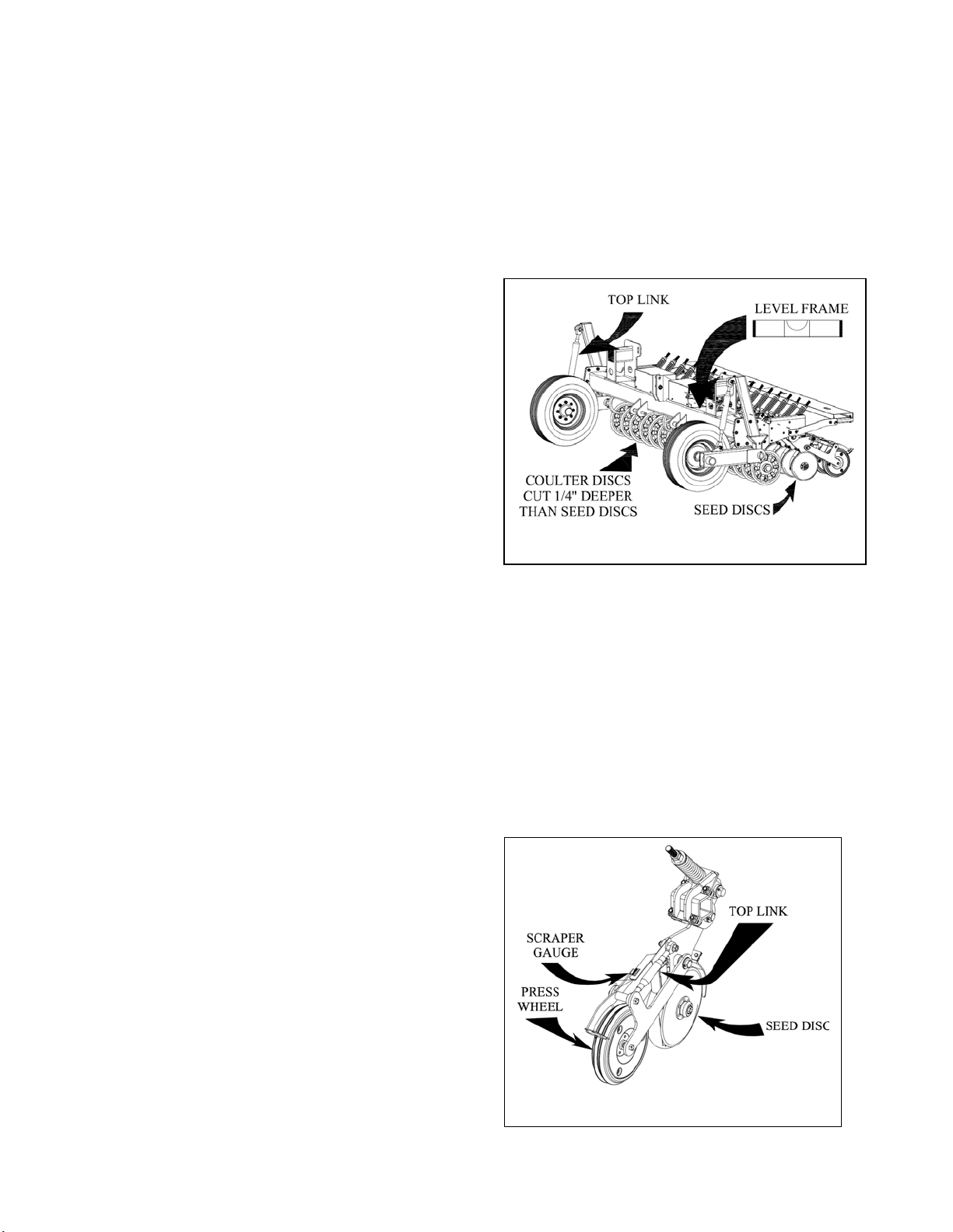
1. Level Multi-drill frame
2. Set Coulter depth
3. Check seed depth and adjust
Each of these steps is detailed below:
1. Level Multi-drill Frame
Whether using the standard 3-point hitch or
the towing hitch, the procedure is the same.
Lower the Multi-drill to the ground. Pull
forward a short distance to allow the coulter
discs to settle into the ground. Place a level
on the main toolbar of the Multi-drill and
check for adjustments (Figure 10). Use the
top link to tilt the frame until its operation is
level.
2. Set Coulter depth
Using a scale, measure the depth of cut the
coulter discs made from the leveling
process. The coulter discs are designed to
cut ¼” deeper then the desired seed depth.
So, if the desired seed depth is ¾”, the
coulter discs are to cut 1” deep.
To adjust depth with a 3-point hitch, the
machine must be lifted in the air and have
each top link on both sides adjusted
accordingly, Figure 10. Use a tape measure
to ensure they are both the same.
To adjust the depth with a tow hitch,
hydraulic cylinder stops are used to limit the
stroke of the gauge wheels. With the
machine in the air, simply add/remove the
stops where the gauge wheel lowers the
coulter discs to desired depth (1/4” increments).
3. Check seed depth and adjust
Once the frame is level and the desired
depth of cut is obtained, a short pass can be
made operating the seeder at the desired
speed (wait until seeder calibration is done
before filling hoppers). This allows the
operator to check the seed depth.
After checking the depth of the seed in the
ground, changes can be made by adjusting
the pressure on the Press Wheel (Figure 11).
The seed can be slightly lowered or lifted
rotating the Top Link on the attached Row
Unit. Shorten the Top Link to lower the
seed deeper and lengthen the Top Link to
raise the seed closer to the surface. The
Scraper Gauge is used as a point of
reference for this final adjustment. Simply
repeat this step until the proper seed depth is
obtained.
Figure 10. Level Multi-drill frame
14
Seeder Calibration
Before operating the seeder, calibration has
to be done in order to take all variables into
account and maximize efficiency of the
seeder. The following steps must be done to
calibrate the seeder:
1. Determine ground speed.
2. Select seed rate.
3. Select seed plates.
4. Use calibration chart to find target
seed weight (Figure 13).
5. Position calibration trough to catch
seed.
6. Operate seeder in air for 1 minute.
7. Compare weight of seed caught to the
target weight in step 4.
8. Manipulate seed plates or electric
motor speed to reach target weight.
9. Repeat steps 5 thru 8 until target
weight is achieved.
10. Check for consistent seed metering.
Each of these steps is detailed below:
1. Determine ground speed
Determining ground speed usually depends on
the terrain in which the seeding is done. In order
to help set a ground speed, it is recommended the
operator make a test pass without operating the
seeder to determine a good starting point. If the
tractor isn’t equipped with a speedometer, a
smartphone app may prove useful.
2. Select seed rate
Most seed varieties have a set standard for what
rate works best. Investigate the seed and
determine what the recommended rate would be
for the particular application. The calibration
chart uses pounds per acre.
3. Set seed plates and hydraulic motor setting
Determine the seed plates needed to achieve the
desired seed rate. The seed plates come in four
different sizes identified with laser etching on one
end. Figure 8 displays a Quick Start Setting
Guide. This chart is used as a point of reference
to help select the proper seed plate, set their
starting position, and choosing the agitator shaft
speed.
If the Quick Start Setting Guide is not helpful for
selecting a seed plate, below is a list of common
seeds under the corresponding seed plates:
¼” Seed Plate: Clover, Grain, Sorghum, Canola
3/8” Seed Plate: Soybeans (low rates)
½” Seed Plate: Wheat and Rye Grass Peas,
Beans (under 60 lbs/acre),
Soybeans (moderate rates)
¾” Seed Plate: Wheat and Rye Grass, Oats,
Mixes, medium to large Grains,
Peas, Beans (over 60 lbs/acre),
Soybeans (high rates)
If the current plates inside the hopper are not the
desired set to use, refer to “Changing Seed Plates”
for step-by-step instructions.
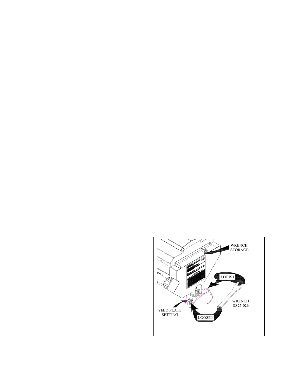
To set the seed plates, the Multi-Drill is supplied
with a wrench, DS27-026, to help as shown in
Figure 12. Use the wrench to loosen the Setting
Bolt sporting the arrow; the wrench also adds
leverage for shifting the plates to the desired
setting. When the setting is adjusted, retighten
the Setting Bolt and store the wrench for future
use.
Figure 12. Seed Plate Setting/Adjustment

15
At this time, the agitator shaft speed should be set
to what the Quick Start Setting Guide
recommends. Figure 6 illustrates the location of
the motor and flow control valve while figure 9
shows the location of the agitator shaft. With
speed in mind, the operator must manually adjust
the flow to the hydraulic motor in order to achieve
the target agitator shaft in revolutions per minute.
4. Find Target Seed Weight
Finding the Target weight is simply done using
the calibration chart seen in Figure 13. Knowing
the ground speed (left side of chart) and the
desired seed rate (top of chart), a target weight to
be caught can be selected.
5. Position Calibration Trough
Every Multi-Drill is equipped with calibration
trough which is used to catch the seed. In order
to do so, the trough should be positioned directly
under the seed discs while the machine is lifted.
6. Operate Seeder for One Minute
With seed loaded in Multi-Drill, use the handheld
control harness to open the seed plates and
energize the hydraulics while the machine in the
air for one minute. The seed should flow through
the seed discs and be captured by the calibration
trough.
7. Weigh and Compare Seed Weight
The seed caught in the calibration trough from
step 6 will need to be weighed on an accurate
digital scale capable of producing pounds (in
decimal form is preferred). If the scale displays
pounds and ounces, divide the ounces by 16 and
add the decimal to the pounds to get the complete
weight.
8. Manipulate Seed Plates/Hydraulic Motor
If the weight of seed is within 10% of the target,
the speed of the hydraulic motor can be modified
to finetune the rate. Otherwise, the seed plates
can be repositioned to dial the seed rate in closer
to the target using the same method outlined in
step 3. If the rate needs to increase, the setting
will be increased; and likewise, the setting will
decrease if the rate needs to be cut down.
9. Repeat Steps as Necessary
Until the target weight is achieved, steps 5
through 8 should be repeated. In some instances,
the seed plates may need to be changed during
this process. Don’t fill hopper until calibration is
complete.
Figure 13. ND-120 Calibration Chart used for Step 4

16
Changing Seed Plates
The seed plates are strategically positioned
between the hopper’s outlet holes (seen when
the hopper is empty) and the “cutoff plate”
which the linear actuator shuttles back and
forth to start and stop seed flow.
Each set of plates are labeled with laser
etching on one side: “left”, “right”, and their
respective sizes.
In order to change the seed plates, the hopper
must be vacuumed/blown clean. If the plates
are removed with seed in the hopper, the seed
can wedge between the “cutoff plate” and the
hopper outlets making it impossible to slide
the next set of plates into place.
The seed plates are changed using the
following steps:
1. To change plates you will need two
9/16” wrenchs and the Adjuster
Wrench, DS27-026. Using the small
end of the Adjuster Wrench, located
on top of chain cover as shown in
Figure 9. Loosen and remove the two
½” carriage head bolts connecting the
adjuster handle to the Adjuster mount
as shown Figure 14.
2. Pull straight out on the adjuster
handle and slide the seed plate
assembly out of the seed box as
shown in Figure 15.
3. Using the 9/16” wrenches, loosen and
remove the 3/8” bolts connecting both
seed plates to the adjuster linkages as
shown in Figure 15.
4. Slide the plates and bushings out of
linkages, set plates to the side, hold
onto the bushings.
5. Select plates you want in machine and
be sure to read etchings on plate
ensuring both plates have the same
size with corresponding sides.
6. Reassemble the desired seed plate
assembly; be sure the left and right
plates are oriented as shown in Figure
15.
7. Take seed plate assembly and slide
back into machine; be sure to put seed
plates on top of cut off plate when
starting to push them into the machine
as shown in Figure 16.
8. Reattach the Adjuster Handle to the
Adjuster Mount as shown in Figure
14, and fasten bolts.
Fi
g
ure 14. Seed Plates – Step 1
Figure 15. Seed Plates – Steps 2,3 & 6
17
CLEANING
After Each Use
Remove large debris such as clumps of dirt,
grass, crop residue, etc. from machine.
Inspect machine and replace worn or damaged
parts.
Replace any safety decals that are damaged,
missing, or not legible.
Grease bearings located on Coulter Disc shaft.
Oil and tighten (if necessary) all chains driving
powered components.
Thoroughly clean hopper(s) vacuuming out all
seed and debris from previous use.
Periodic or Before Extended Storage
Remove large debris such as clumps of dirt,
grass, crop residue, etc. from machine.
Remove the remaining debris with a low-
pressure washer spray:
1. Be careful when spraying near scratched or
torn safety decals or near edges of decals as
water spray can peel decal off surface.
2. Be careful when spraying near chipped or
scratched paint as water spray may lift paint.
3. If a pressure washer is used, follow the
advice of the pressure washer manufacturer.
Inspect machine and replace worn or damaged
parts.
Check all hardware and ensure proper torque is
present.
Sand down scratches and the edges of area of
missing parts and coat with First Products spray
paint of matching color.
Replace any safety decals with that are missing
or not legible. See Safety Decals section for
location drawing.
Cover the seeder with supplied tarp when the
Multi-drill is being stored.
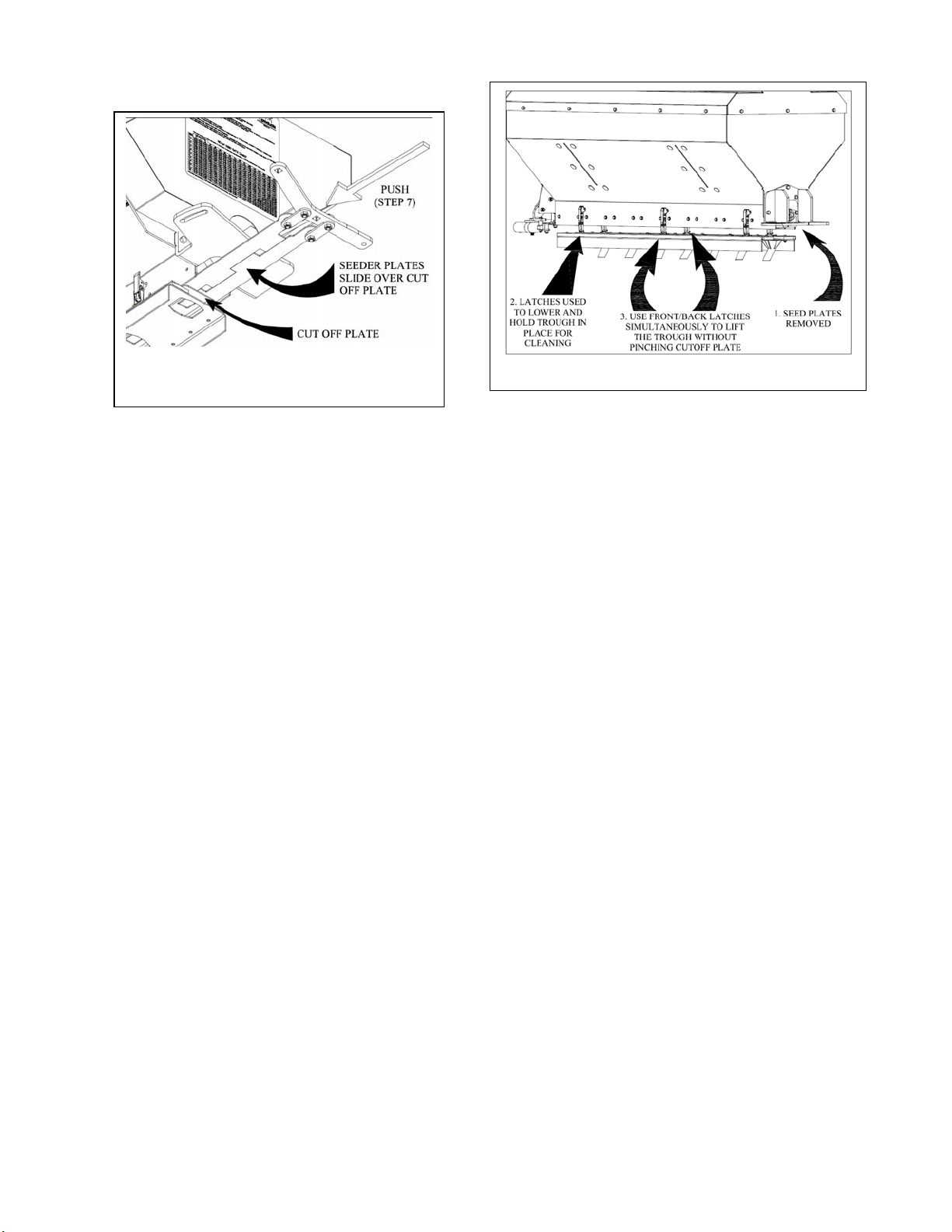
NOTE: Occasionally, it may be necessary to
lower the trough as illustrated in Figure 18 to
thoroughly clean all the moving components in
the hopper to promote easier calibration and
functionality in the future.
1. Remove Seed Plates as explained in
previous section.
2. Use the latches to lower and hold the trough
in place while using water or compressed air
to clean all moving parts and their
corresponding surfaces. If water is used, do
not reassemble until everything is
thoroughly dry.
3. It is best to use the latches on the front and
back to simultaneously lift the trough back
into place making sure not to pinch the Cut
Off Plate between the trough and the hopper.
4. Install desired Seed Plates for future use.
Figure 16. Seed Plates – Step 7 Figure 17. Trough lowered and cleaned

18
WARRANTY INFORMATION
ONE YEAR LIMITED WARRANTY
FIRST PRODUCTS INC. WARRANTS THIS PRODUCT TO BE FREE OF DEFECTS IN MATERIALS
AND WORKMANSHIP FOR A PERIOD OF TWELVE MONTHS FROM THE ORIGINAL DELIVERY
DATE. THIS WARRANTY DOES NOT COVER PARTS CAUSED TO BE DEFICIENT DUE TO
NORMAL WEAR, MISUSE, ACCIDENTS, OR LACK OF PROPER MAINTENANCE.
ANY PARTS THOUGHT TO BE DEFECTIVE MUST BE RETURNED TO THE FACTORY FOR
WARRANTY CONSIDERATION. A RETURN AUTHORIZATION NUMBER MUST BE OBTAINED
AND CLEARLY MARKED ON ALL PACKAGES OF PARTS REQUIRING RETURN TO THE
FACTORY.
THE OBLIGATION OF FIRST PRODUCTS INC. UNDER THIS WARRANTY SHALL BE
EXCLUSIVELY LIMITED TO REPLACEMENT OF PARTS DETERMINED TO BE DEFECTIVE BY
FIRST PRODUCTS INC. WITH FREIGHT PREPAID. IN NO EVENT SHALL FIRST PRODUCTS INC.
BE LIABLE FOR INDIRECT, INCIDENTAL, OR CONSEQUENTIAL DAMAGES IN CONNECTION
WITH THE USE OF THIS PRODUCT.
FIRST PRODUCTS INC. RESERVES THE RIGHT TO MAKE CHANGES OR ADD IMPROVEMENTS
TO ITS PRODUCTS AT ANY TIME WITHOUT OBLIGATION TO MAKE SUCH CHANGES OR
IMPROVEMENTS ON PRODUCTS SOLD PREVIOUSLY.
WARRANTY CLAIMS ARE PAID USING A JOB STANDARD (AUTHORIZING MAN HOURS)
USING THE APPROPRIATE TIME FRAME ALLOWED FOR EACH PART REPLACED OR LABOR
FUNCTIONS PERFORMED. THIS JOB STANDARD LIMITS THE MAN HOURS AUTHORIZED BY
TASK. IT DOES NOT SET A SPECIFIC HOURLY RATE BUT LIMITS THE AUTHORIZED MAN
HOURS THAT WILL BE PAID BY EACH TASK. MILEAGE IS NOT PAID.

This manual suits for next models
1
Table of contents
Other First Products Drill manuals


Popular Drill manuals by other brands


Stanley
Stanley STDH7013 instruction manual

Universal Tool
Universal Tool UT8892 Series General Safety Information & Replacement Parts

Makita
Makita FD04 instruction manual

Cocraft
Cocraft JOZ-SP01-1020 instruction manual

Black & Decker
Black & Decker CRT129 instruction manual

Berner
Berner RS25e Use instruction


