fisair HEF7 Series Manual

FISAIR S.L.U. C/ Uranio, 20, 28330 Madrid, Spain.
HEF7 SERIES
INSTALATION AND MAINTENANCE MANUAL
Adiabatic cooling system for
Air-condensed Water Chillers
MHEF7-EN-21-0
In compliance with European Union standards for machinery safety,
it is essential to read this manual in detail before installing units.

HEF7 series manual 2

HEF7 series manual 3
Index
1. General description.............................................................................................................................4
1.1. Safety instructions........................................................................................................................5
2. HEF7 nomenclature............................................................................................................................7
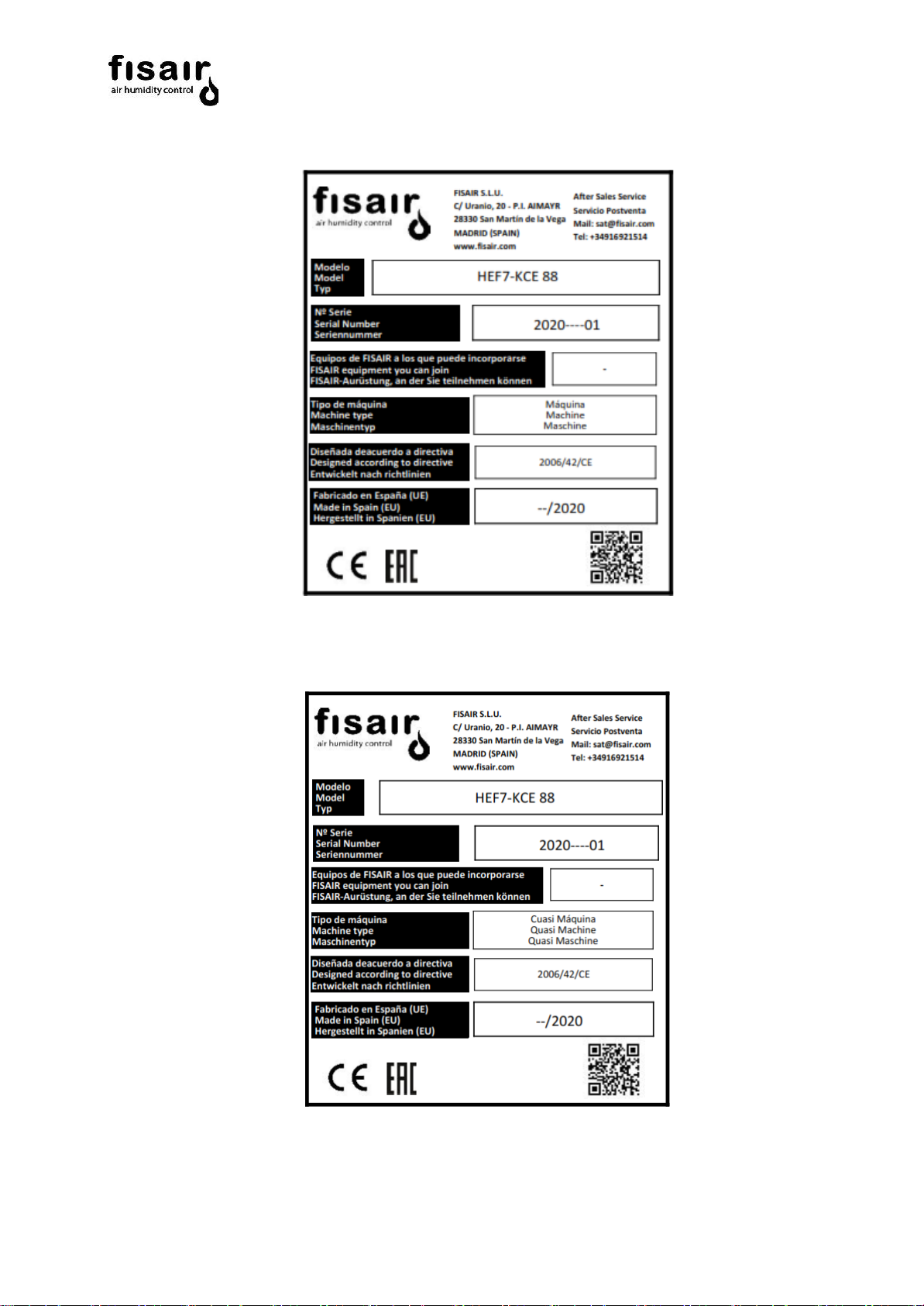
3. Rating plate and machine type............................................................................................................8
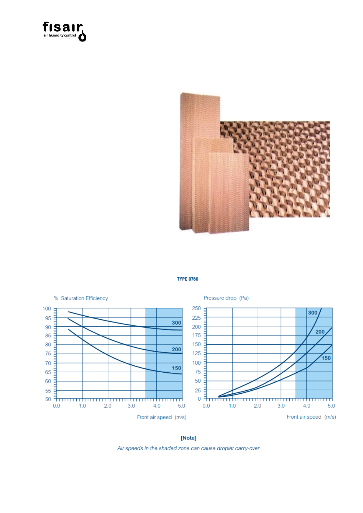
4. High efficiency HEF7 evaporative panel............................................................................................10
4.1. ORGANIC EVAPORATIVE PANEL............................................................................................10
4.2. INORGANIC EVAPORATIVE PANEL........................................................................................11
5. Unit components...............................................................................................................................12
6. Operating principle............................................................................................................................14
7. Installation requirements...................................................................................................................15
8. Connections and regulation...............................................................................................................17
9. Recirculation pump electricity connection..........................................................................................19
10. Level detector connection..............................................................................................................20
11. Solenoid valve electricity connection .............................................................................................22
12. Connection of the motor-zone valve N.C. for automatic emptying / draining .................................23
13. Setting the valve regulating irrigation flow......................................................................................26
14. Setting the valve regulating the bleed-off flow...............................................................................27
15. Start-up recommendations.............................................................................................................29
16. Maintenance and cleaning.............................................................................................................30
16.1. Evaporative humidification: a natural method that does not carry bacteria. ................................30
16.2. Cleaning.....................................................................................................................................30
16.2.1. General......................................................................................................................................30
16.2.2. Scale formation process.............................................................................................................31
16.2.3. Desinfection...............................................................................................................................31
17. Machine conformity declaration .....................................................................................................34
18. Cuasi machine conformity declaration ...........................................................................................35
19. WARRANTY..................................................................................................................................36

HEF7 series manual 4
1. General description
EVAPORATIVE HUMIDIFIER
OPERATING PRINCIPLE
FISAIR evaporative humidifier units are designed to
increase the water vapour content of the treated air,
through the natural evaporation of water in its liquid
phase. The air flow being treated passes through a
cellular panel, which is watered by an irrigation system.
The panel is made up of undulating sheets of organic or
inorganic paper containing stiffening agents and water
absorbers.
Panels are laid out in criss-crossing channels to provide
a large surface area for air-water contact, which
maximizes water evaporation and at the same time
minimizes resistance to the air flow passing through
(pressure drop).
See the graph of evaporative performance and pressure
drop for the panel in relation to the air speed
FISAIR evaporative humidifiers work in a similar way to
natural phenomena occurring in rivers, lakes and seas.
All that is added to the air is pure water vapour.
PROVISIONAL STORAGE
During storage, keep units dry and protected
against the elements.
[Note]:Thermo-hygrometric conditions of the
storage area:
Temperature: [-10… 50ºC]
Relative Humidity: [5… 95%HR]
No condensation

HEF7 series manual 5
1.1. Safety instructions
FISAIR se exime de cualquier responsabilidad a menos que se cumplan con todas las instrucciones de
instalación y funcionamiento proporcionadas por FISAIR, o si los productos han sido modificados o
alterados sin el consentimiento por escrito de FISAIR, o si tales productos han sido sometidos a un
mal uso, mala manipulación, alteración, mantenimiento inadecuado o muestran consecuencias de
accidente o utilización negligente. Estas situaciones pueden ser una conexión de alimentación
incorrecta, golpes con otros objetos, anulación de seguridades, etc.
Please read these safety notes carefully and examine the equipment to become familiar with it before installing,
commissioning or servicing.
The following symbols or messages may appear in this document or on the equipment. They warn of potential
hazards or provide information that may help you clarify or simplify a procedure.
Attention, Live Current
The presence of this symbol on a hazard or warning label indicates that there is
a risk of electrocution, which can lead to personal injury or life-threatening
conditions if the instructions are not followed.
Atención
The presence of this symbol on a hazard or warning label indicates that there is
a risk of electrocution, which can lead to personal injury or life-threatening
conditions if the instructions are not followed.
Installation of a residual current device in the power supply line.
The installer has to install a specific residual current device in the machine's electrical power
circuit.

HEF7 series manual 6
General points
•If you notice that something is not working properly, switch off the unit immediately and take steps to
ensure that it does not switch on again. All faults must be corrected immediately.
•Use duly qualified personnel to carry out repair work. This will ensure that the unit operates safely.
•Use only original FISAIR replacement parts.
•Refer to local regulations that restrict or regulate the use of this humidifier.
How the unit works
•Do not jeopardise the safety of the unit.
•Periodically check the device's protection and alert devices.
•The unit's safety fittings must not be removed or disabled.
Installing, Disassembling, Maintaining and Repairing the unit
•The machine must not be manipulated when it is operating.
•Switch off the unit's power supply when conducting maintenance work or making repairs to the unit.
•Never add components to the unit without prior written approval from FISAIR.
About the electrical components
•Any work that affects the electrical components must be carried out by qualified electricians.
•Use only original, correctly calibrated fuses.
•Carry out periodic checks of the electrical unit.
•All defects, such as loose connections or burnt cables, must be repaired immediately.
The HEF2E control panel load break switch, whether it is external
or a FISAIR CCB2.0 or CCE2.0 panel, must be set to position “0”
(lock) before performing any maintenance on the unit.

HEF7 series manual 7
2. HEF7 nomenclature
HEF7 MODEL
HEF7 - VCS906-E6
Factory chiller model
PUMPING GROUP FOR HEF7
Pumping group - 230V-IN-50/60Hz
Line voltage
Basic control panel / (CONTROL PANEL)
CCB2.0- 230V-IN-50/60Hz
Line voltage

HEF7 series manual 8
3. Rating plate and machine type
The rating plate provides essential information about the technical features of the machine.
The EC Machinery Safety Regulation requires all machinery operated within the European Economic
Community to have a rating plate indicating its main features, the machine serial number and the manufacturer's
name inscribed in a durable manner.
According to article 2, section g of the Machinery Directive 2006/42/CE - RD 1644/2008, ‘partly completed
machinery’ means
“an assembly which is almost machinery, but which cannot in itself perform a specific application. A drive
system is partly completed machinery. Partly completed machinery is intended only to be incorporated into or
assembled with other machinery or other partly completed machinery or equipment, thereby forming machinery
to which this Directive applies”
Therefore, the HEF7 device is classified according to whether it is delivered with a CCB2.0 control panel:
•If only the HEF7 device is supplied →Partly completed machinery (quasi-machine)
•If the HEF7 device + CCB2.0 control panel are supplied→Machine
•If the HEF7 device + CCB2.0 control panel are supplied separately →Partly completed machinery
+ Partly completed machinery ≠ Machine
The rating plate shows the following information for the equipment:
•Model: description of the particular HEF7 device
•Serial No.: equipment serial number
•FISAIR devices it can be joined with
•Machine type: Machine or Partly completed machinery
•Designed in accordance with directive
•Made in Spain (EU): Place and date of manufacture
•QR code for technical assistance service and warranty activation

HEF7 series manual 9
Machine type rating plate:
Partly completed machinery (quasi-machine) type rating plate:

HEF7 series manual 10
4. High efficiency HEF7 evaporative panel
4.1. ORGANIC EVAPORATIVE PANEL
• Maximum performance: Organic Media is
designed to provide the largest possible air-
to-water contact surface area
(approximately 460 m2/m3). Such a large
area enables optimal evaporative cooling
and humidification from the evaporation.
•Maximum freshness: it works as a natural
filter purifying the entry air. Carefully designed
channelling eliminates dust particles and
mineral deposits from the air, which are trapped
on the evaporative surface.
• Maximum durability: made from special
cellulose paper impregnated with insoluble
chemical components in order to ensure a
long working life in the system.
• Maximum resistance: appropriate bleed-off
and regular brushing make it possible to be
used in imperfect water and air conditions.

HEF7 series manual 11
4.2. INORGANIC EVAPORATIVE PANEL
These panels are made of fibreglass with a special coating
to enable a greater absorption capacity and ensure
constant evaporative humidification and cooling, even at
high air speeds. They are made of fireproof inorganic
material.
They are ideal for humidifiers placed after air treatment
and heater units, and for the pre-cooling of gas turbines.
• Inorganic and fireproof
(in accordance with EURO Class A2, S1, D0)
• Low humidification/cooling energy costs
• Precise control
• No risk of oversaturation
• No need for water treatment
• Safe and hygienic

HEF7 series manual 12
5. Unit components
1
2
4
3
7 5
6

HEF7 series manual 13
E
L
H
The unit serial number and the dimensions of the cassette are required for evaporate cassette spare parts.
L = Cassette length H = Cassette height E = Cassette thickness
For further information on parts of systems, please contact the manufacturer.
Brand
Code
Descriptions
Units
1
-
REGULATION VALVE
1
2
62000075
REGULATION VALVE
1
3
71090008
SOLENOID VALVE
1
4
64220314
LEVEL SENSOR
1
5
63390021
VALVE ACTUATOR
1
6
63330051
2-WAY VALVE
1
7
65330005
PUMP
1

HEF7 series manual 14
6. Operating principle
A Water Supply
B Constant bleed-off
C Overflow
D Drainage
1 Regulation valves with Flow meter (Irrigation)
2 Regulation valves with Flow meter (Bleed-off)
3 Filling Solenoid Valves
4 Max/Min level detector
5 Valves with actuator (Drainage)
7 Water Recirculation Pump

HEF7 series manual 15
400 mm
7. Installation requirements
OVERVIEW
To ensure optimum performance and maintenance,
humidifiers must be placed on a level surface, with a
drain, so possible leaks during installation, start-up,
operation and maintenance can be controlled.
Assembly in conjunction with an air-cooling unit must
ensure the air passes through the evaporative panels, by
closing off the perimeter sides to prevent a potential
bypass in the air flow and ensure the adiabatic
performance of the design.
PLACEMENT AND SERVICING SPACE
Humidifiers are normally placed just before the coil
and before the sensible exchange in the air cooling
system.
A 1m space should be left in front of the unit section
for inspection and servicing.
Note: Thermo-hygrometric conditions of the operating
place (*)
Temperature: [5… 40ºC]
Relative humidity: [5… 97%HR]
In case the pump does not work (with it consecuence
of lack of irrigation) is advisable not to exceed 50ºC in
the temperature of the air to be processed,
With the pump running, it cannot exceed 40ºC on the
pump side.
Irrigation system EXPELLED AIR Axial fan
High performance
and low
pressure drop
evaporative
panel
EXTERIOR AIR
PRE-
COOLED AIR
Condensation
coil
Stainless steel
frame and
surround
Drainage system

HEF7 series manual 16
EVAPORATIVE PANEL DRYING TIME
To ensure complete drying of the cooling pad, after a work period, the air fan of the UTA must be working during the
times set out in the following table:
Before drying the evaporation panel, the ventilation must be stopped for 10 minutes and watering continued with the
cassettes. This is done by keeping the water recirculation or direct water irrigation to remove all possible minerals
stuck to the panel. Afterwards, the recirculation is turned-off and the ventilation system re-started for the estimated
time on the above table.

HEF7 series manual 17
2H
H
8. Connections and regulation
OVERVIEW
FISAIR HEF7 evaporative humidifiers essentially
work in accordance with the irrigation of the
evaporative panels. Humidification occurs whenever
there is an air current passing through and the water
pump irrigates the panels.
[Note] In order to eliminate superficial dust on the
panels, and to prevent its transmission to occupied
areas, the water irrigation pump should be left
operating for 6 hours with no air flow, to wash the
panels. Subsequently, the water used for washing
should be drained before normal start-up.
WATER CONNECTIONS
• Connect the water network supply to the ½” filter in Y,
and this to the solenoid supply valve.
• Connect the common outlet for the 50mm diameter
drain / overflow / constant bleed-off to the drainage
network.
• The water outlet connection to the drain must have a
water trap or seal, as shown in the figure, large enough to
overcome system pressure in order for the tank to drain
completely, for hygiene reasons. The system has the
normal slope of any drainage line.
Water trap for positive pressures
Hmin. (mm)= P(Pa)/10
P= Total pressure
2H>H
Note 1: The water level should never be below the
foot of the pump water. The level below this foot of
water will damage the pump irreparably.
Note 2: It is very important that the maximum
temperature of the basin feed water does not
exceed the 25-30ºC range as the saturation
efficiency performance could be affected.

HEF7 series manual 18
Remark 3: How to avoid standing water in the water supply:
oIf the distance from the supply valve to the main water supply line (with continuous water flow) ≥ 2m:
Install a 3-way valve, before the cut-off valve, with a return line to the main water supply line, to avoid water
retention.
oIf the distance from the supply valve to the main water supply line (with continuous water flow) < 2m:
It is not necessary to install the 3-way valve.

HEF7 series manual 19
9. Recirculation pump electricity
connection
Connect the electricity supply cable to
the terminal box of the water irrigation
pump using an appropriate connection
(IP-55 or higher).
La protección y operativa de alimentación
eléctrica a la bomba debe ser determinada
por el proyectista del sistema.
H/m
10
8
6
4
2
0
TM 32/8
0 2 4 6 8 10 12 14 Q/m5/h

HEF7 series manual 20
PUMP TECHNICAL DATA
10. Level detector connection
1. Minimum level detector (low level S1):
Level detector must be connected to protect the water pump
working. Water level in basin is detected by this level detector (J17
sensor indicates minimum water level NO, take a look on CCB2.0
manual).
2. Maximum level detector (high level S2):
The maximum level is used as a security system in a float valve
regulation water feed possible failure event. It must not be used to
regulate the fresh water inlet. In case the equipment has a filling
solenoid valve, connect it to this level so that it is cut for safety
(J16 sensor indicates maximum water level NC, take a look on
CCB2.0 manual).
Remark: Max Voltage: 175 Vcc / 110 Vca
Max Current: 1 Acc
Temperature: -20...120ºC
Min. Density: 0, 75 gr/cm3
Figure 1: Explanatory diagram to confirm which components are
managed by levels S1 and S2.
It’s not a unifilar diagram.
Electrical power supply
Service voltage (Vac)
230
Frequency (Hz)
50
Motor nominal power (W)
370
Consumption (A)
2,1
Degree of protection
Degree of protection according to
EN 60529
IP 68
Enviromental conditions
Max. fluid temperature (ºC)
35
Functional data
Max working height (m)
7
Max. working flow (m3/h)
10
N.C. = normally closed ALTO= High level S2
N.A. = normally open BAJO= Low level S1
C= Common
Example connection to CCB2.0
Not Connected
C-S2
C-S1
Other manuals for HEF7 Series
1
This manual suits for next models
1
Table of contents
Popular Accessories manuals by other brands

Qwik Time
Qwik Time QT-5 instructions

CHIEF
CHIEF Keyboard Tray Accessory KSA1021 installation instructions

ROSE DISPLAYS
ROSE DISPLAYS ANOFRAME SQUARE WITH NO LOAD WITH MULTICLIPS manual

Xylem
Xylem wtw NitraVis 705 IQ operating manual

Orno
Orno ERATO AC manual

ARoma trick
ARoma trick A-Trick 500 Classic user guide