FISCHER NK10 Series User manual

Operating manual
NK10
Fill Level Limiter
09005111 • BA_EN_NK10 • Rev. ST4-E • 01/19
*09005111*

| Masthead FISCHER Mess- und Regeltechnik GmbH
2 / 28 BA_EN_NK10
Masthead
Manufacturer: FISCHER Mess- und Regeltechnik GmbH
Bielefelderstr. 37a
D-32107 Bad Salzuflen
Telephone: +49 5222 974 0
Telefax: +49 5222 7170
eMail: [email protected]
web: www.fischermesstechnik.de
Technical editorial team: Documentation representative: T. Malischewski
Technical editor: R. Kleemann
All rights, also those to the translation, reserved. No part of this document may
be reproduced or processed, duplicated or distributed using electronic systems
or any other form (print, photocopy, microfilm or another process) without the
written consent of the company FISCHER Mess- und Regeltechnik GmbH, Bad
Salzuflen.
Reproduction for internal use is expressly allowed.
Brand names and procedures are used for information purposes only and do
not take the respective patent situation into account. Great care was taken
when compiling the texts and illustrations; Nevertheless, errors cannot be ruled
out. The company FISCHER Mess- und Regeltechnik GmbH will not accept any
legal responsibility or liability for this.
Subject to technical amendments.
© FISCHER Mess- und Regeltechnik 2015
Version history
Rev. ST4-A 01/15 Version 1 (first edition)
Rev. ST4-B 06/16 Version 2 (Correction)
Rev. ST4-C 04/17 Version 4 (Dimensional drawings changed)
Rev. ST4-D 11/18 Version 5 (Dimensional drawing/DNV-GL/CE declaration
changed)
Rev. ST4-E 01/19 Version 6 (Order codes optional information (SIL))

FISCHER Mess- und Regeltechnik GmbH Table of Contents
BA_EN_NK10 3 / 28
Table of Contents
1 Safety guidelines ............................................................................................................................................4
1.1 General .....................................................................................................................................................4
1.2 Personnel Qualification.............................................................................................................................4
1.3 Risks due to Non-Observance of Safety Instructions ...............................................................................4
1.4 Safety Instructions for the Operating Company and the Operator............................................................4
1.5 Unauthorised Modification ........................................................................................................................4
1.6 Inadmissible Modes of Operation .............................................................................................................4
1.7 Safe working practices for maintenance and installation work .................................................................5
1.8 Pictogram explanation ..............................................................................................................................5
2 Product and functional description ..............................................................................................................6
2.1 Delivery scope ..........................................................................................................................................6
2.2 Use as intended........................................................................................................................................6
2.3 Function diagram ......................................................................................................................................6
2.4 Design and mode of operation..................................................................................................................7
3 Installation and assembly..............................................................................................................................8
3.1 Process connection ..................................................................................................................................8
3.2 Electrical connections ...............................................................................................................................8
4 Commissioning...............................................................................................................................................9
4.1 Generalities...............................................................................................................................................9
4.2 Function test .............................................................................................................................................9
5 Servicing .......................................................................................................................................................10
5.1 Maintenance ...........................................................................................................................................10
5.2 Transport ................................................................................................................................................10
5.3 Service....................................................................................................................................................10
5.4 Disposal ..................................................................................................................................................10
6 Technical data...............................................................................................................................................11
6.1 General ...................................................................................................................................................11
6.2 Application conditions .............................................................................................................................11
6.3 Switch contacts.......................................................................................................................................11
6.4 Measurement accuracy ..........................................................................................................................11
6.5 Directives and certificates.......................................................................................................................12
6.6 Construction design ................................................................................................................................12
7 Order Codes..................................................................................................................................................17
8 Attachments..................................................................................................................................................18
8.1 Declarations of conformity ......................................................................................................................18
8.2 Type testing certificates ..........................................................................................................................20
8.3 DIN CERTCO Certification DIN 4754-3 ..................................................................................................24
8.4 SIL Certificate .........................................................................................................................................26
8.5 EAC Declaration .....................................................................................................................................28

1 | Safety guidelines FISCHER Mess- und Regeltechnik GmbH
4 / 28 BA_EN_NK10
1 Safety guidelines
1.1 General
This operating manual is an integral part of the product and therefore needs to
be kept close to the instrument in a place that is accessible at all times to the re-
sponsible personnel.
The following sections, in particular instructions about the assembly, commis-
sioning and maintenance, contain important information, non-observance of
which could pose a threat to humans, animals, the environment and property.
The instrument described in these operating instructions is designed and manu-
factured in line with the state of the art and good engineering practice.
1.2 Personnel Qualification
The instrument may only be installed and commissioned by specialized person-
nel familiar with the installation, commissioning and operation of this product.
Specialized personnel are persons who can assess the work they have been
assigned and recognize potential dangers by virtue of their specialized training,
their skills and experience and their knowledge of the pertinent standards.
1.3 Risks due to Non-Observance of Safety Instructions
Non-observance of these safety instructions, the intended use of the device or
the limit values given in the technical specifications can be hazardous or cause
harm to persons, the environment or the plant itself.
The supplier of the equipment will not be liable for damage claims if this should
happen.
1.4 Safety Instructions for the Operating Company and the Operator
The safety instructions governing correct operation of theinstrument must be
observed. The operating company must make them available to the installation,
maintenance, inspection and operating personnel.
Dangers arising from electrical components, energy discharged by the medium,
escaping medium and incorrect installation of the device must be eliminated.
See the information in the applicable national and international regulations.
Please observe the information about certification and approvals in the Tech-
nical Data section.
1.5 Unauthorised Modification
Modifications of or other technical alterations to the instrument by the customer
are not permitted. This also applies to replacement parts. Only the manufacturer
is authorised to make any modifications or changes.
1.6 Inadmissible Modes of Operation
The operational safety of this instrument can only be guaranteed if it is used as
intended. The instrument model must be suitable for the medium used in the
system. The limit values given in the technical data may not be exceeded.
The manufacturer is not liable for damage resulting from improper or incorrect
use.
FISCHER Mess- und Regeltechnik GmbH Safety guidelines | 1
BA_EN_NK10 5 / 28
1.7 Safe working practices for maintenance and installation work
The safety instructions given in this operating manual, any nationally applicable
regulations on accident prevention and any of the operating company's internal
work, operating and safety guidelines must be observed.
The operating company is responsible for ensuring that all required mainten-
ance, inspection and installation work is carried out by qualified specialized per-
sonnel.
1.8 Pictogram explanation
DANGER
Type and source of danger
This indicates a direct dangerous situation that could lead to death or serious
injury (highest danger level).
a) Avoid danger by observing the valid safety regulations.
WARNING
Type and source of danger
This indicates a potentially dangerous situation that could lead to death or ser-
ious injury (medium danger level).
a) Avoid danger by observing the valid safety regulations.
CAUTION
Type and source of danger
This indicates a potentially dangerous situation that could lead to slight or seri-
ous injury, damage or environmental pollution (low danger level).
a) Avoid danger by observing the valid safety regulations.
NOTICE
Note / advice
This indicates useful information of advice for efficient and smooth operation.
2 | Product and functional description FISCHER Mess- und Regeltechnik GmbH
6 / 28 BA_EN_NK10
2 Product and functional description
2.1 Delivery scope
• NK10 according to specification (see order code)
• Operating Manual
• SIL safety manual for version NK10 … U0600
2.2 Use as intended
The NK10 fill level limiter is used in thermo-technical and process plants as a
safeguard against the fill level falling below the lowest permissible level. As a
limiter the device conforms to the requirements of DIN 4754.
The devices in this series are...
• type-tested in compliance with DIN 4754-3
• certified to DNVGL-CG-0339
• Functional safety as per IEC 61508/61511
• certified to directive 2014/68/EU
Copies of the certificates can be found in the appendix to the operating manual.
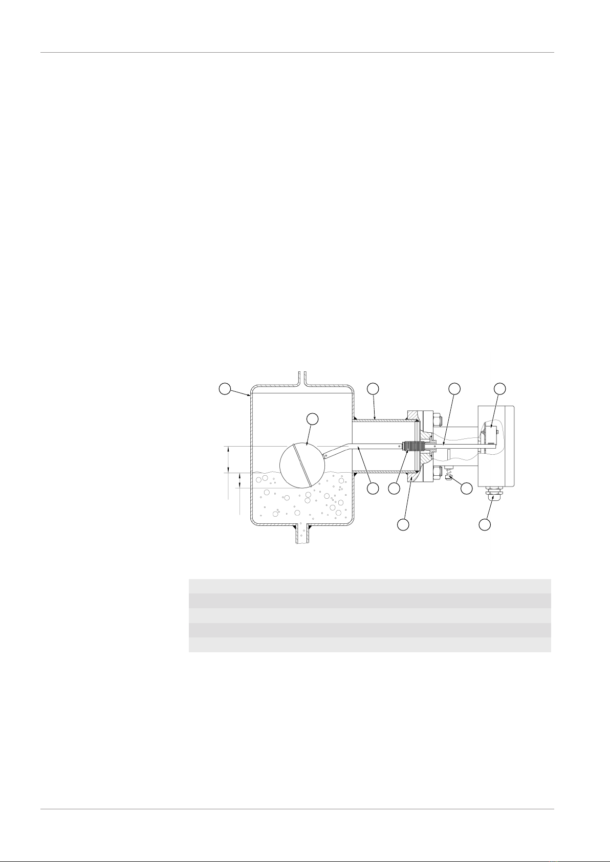
2.3 Function diagram
1
2 3
6
4
9
8 7
10
approx. 10 mm
approx. 60 mm
5
Fig.1: Function diagram
1 Swimmer 2 Swimmer rod
3 Metal bellows 4 Test button
5 Switch lever 6 Micro-switch S1
7 Cable screw connection 8 Flange and counter-flange
9 Welding socket 10 Tank

FISCHER Mess- und Regeltechnik GmbH Product and functional description | 2
BA_EN_NK10 7 / 28
2.4 Design and mode of operation
The swim system of the fill level limiter is contained in the fluid-filled reservoir
(expansion tank). The swimming motions generated by changes in the fill level
are transmitted directly to the micro-switch S1 by a swimmer rod sealed in a
stainless-steel bellows. The fulcrum of the swimmer rod is located outside of the
pressure chamber.
There is also a test button outside the pressure chamber with which a function
check as per DIN 4754-3 can be run without lowering the fill level. When
pressed, the body of the swimmer is moved against its buoyancy.
The factory default switching point of micro-switch S1 is set so that it switches
when the swimmer rod is horizontal. The optional warning switch S2 switches
approx. 2.5 mm before S1.
The fill level height at which switching is triggered depends on the density of the
heat carrier. The lowest density at which a secure function is guaranteed is 0.6
kg/dm³.
When the medium has a density of 1.0 kg/dm³, the switching level is approx.
60mm below the middle of the flange or socket.

3 | Installation and assembly FISCHER Mess- und Regeltechnik GmbH
8 / 28 BA_EN_NK10
3 Installation and assembly
NOTICE!The information in the safety manual must be observed in con-
nection with equipment with functional safety.
3.1 Process connection
The process connection may be realised by authorized and qualified specialized
personnel.
The unit is set ex-works for horizontal installation. Only this installation position
is allowed.
Dangers caused by pressure on the instrument are to be prevented with suit-
able measures.
The flange and/or process connections are designed for a working temperature
of max. 400 °C and a working pressure of max. 20 bar.
CAUTION
The data of the flange used may be lower.
Please check the actual data in the technical data section.
There are a range of flanges and welded hexagon nipples with which the device
can be installed on-site. Take care that the side of the device marked TOP
faces upwards when being installed.
NOTICE!Please check:
• The swimmer must be able to move freely in the vertical direction!
• Test the switching function using the test button.
3.2 Electrical connections
• By authorized and qualified specialized personnel only.
• When connecting the unit, the national and international electro-technical
regulations must be observed.
• Disconnect the system from the mains, before electrically connecting the
device.
• Install the consumer-adapted fuses.
• Do not connect the connector if strained.
When laying the electrical supply lines, ensure that no short circuit between the
electrical conductors and the surroundings can occur.
A locking and unlocking system as per DIN 4754-3 must be incorporated, if the
device is used as a fill level limiter. This safety system must conform to DIN
50156 / VDDE 0116.
3.2.1 Circuit diagram
123
Test button
123 456
1 Switch
(S1)
2 Switch
(S1 with warn switch S2)
PE PE PE
Fig.2: Circuit diagram

FISCHER Mess- und Regeltechnik GmbH Commissioning | 4
BA_EN_NK10 9 / 28
4 Commissioning
4.1 Generalities
All electrical supply, operating and measuring lines and the pressure connec-
tions must have been correctly installed before starting operation and the flange
connections must have been correctly made. All supply lines are arranged so
that there are no mechanical forces acting on the device.
NOTICE!Leak test
The leak tightness of the flange connection must be tested in the course of the
system leak tests.
4.2 Function test
There is a test button outside the pressure chamber with which a function check
as per DIN 4754-3 can be made without lowering the fill level. When pressed,
the body of the swimmer is moved against its buoyancy.
The factory default switching point of switch S1 (clamps 1, 2, 3) is set so that it
switches when the swimmer rod is horizontal. The optional warning switch S2
switches ca. 2.5 mm before S1.
Check the function of the unit:
• Check the switching function (with the aid of the test button) in combination
with the following components.
• Check the swimmer via the buoyancy behaviour after pressing the test but-
ton.
If the result of the function test is negative, the fill level limiter must be taken out
of operation and the process must be kept safe by other means.
5 | Servicing FISCHER Mess- und Regeltechnik GmbH
10 / 28 BA_EN_NK10
5 Servicing
5.1 Maintenance
CAUTION!Observe the system safety and operating regulations.
The instrument is maintenance-free. We recommend the following regular in-
spection to guarantee reliable operation and a long service life:
• Check the switching function (with the aid of the test button) in combination
with the following components.
• Check the seal tightness of the flange connection.
• Check the electrical connections (cable clamp connection).
The exact test cycles need to be adapted to the operating and environmental
conditions. If several components of the unit interact, all operating instructions
of the other units also need to be observed.
5.2 Transport
The measuring device must be protected against impacts. It should be transpor-
ted in the original packaging or a suitable transport container.
5.3 Service
All defective or faulty devices should be sent directly to our repair department.
Please coordinate all shipments with our sales department.
WARNING
Process media residues
Process media residues in and ondismantled devices can be a hazard to
people, animals and the environment. Take adequate preventive measures. If
required, the devices must be cleaned thoroughly.
Return the device in the original packaging or a suitable transport container.
5.4 Disposal
Please help to protect the environment by always disposing of the work pieces
and packaging materials in compliance with the valid national waste and recyc-
ling guidelines or reuse them.

FISCHER Mess- und Regeltechnik GmbH Technical data | 6
BA_EN_NK10 11 / 28
6 Technical data
6.1 General
Please also observe the order code here.
6.2 Application conditions
Ambient temperature -10 … +70 °C
Storage temperature -20 … +85 °C
Max. temperature of medium Depends on model
Specific minimum density of medium ρ = 0.6 kg/dm3
Installation position horizontal
Type of protection IP 55 acc. to DIN EN 60529
Variant Max. working pressure: Max. temperature of medium
NK10 1 … 20 bar 400°C
NK10 2 … 20 bar 400°C
NK10 3 … 10 bar 350°C
NK10 4 … 16 bar 400°C
NK10 5 … 16 bar 400°C
NK10 6 … 20 bar 400°C
NK10 7 … 20 bar 400°C
NK10 A … 10 bar 350°C
NK10 B … 20 bar 400°C
NK10 F … 20 bar 400°C
NK10 G … 20 bar 400°C
NK10 H … 20 bar 400°C
NK10 K … 150 lbs 400°C
NK10 M … 300 lbs 400°C
NK10 N … 300 lbs 400°C
NK10 P … 300 lbs 400°C
6.3 Switch contacts
Maximum load data at ohmic load.
250 V AC 6A
250 V DC 250 mA
6.4 Measurement accuracy
Switch hysteresis approx. 6 mm
Switching point differential between S1 and
S2 (+)
max. 30 mm
Switching point differential on the
medium surface
dependent on medium density
(+) only for two micro-switches
6 | Technical data FISCHER Mess- und Regeltechnik GmbH
12 / 28 BA_EN_NK10
6.5 Directives and certificates
Directives Applicable standards
Pressurised Vessel Directive 2014/35/
EU
DIN EN 13445-1:2013-12
DIN 4754-3:2015-03
Low-Voltage Directive 2014/35/EU DIN EN 61010-1:2011-07
examination Certificate no.
EC type testing in compli-
ance with Pressurised Ves-
sel Directive
Module
B
Cert. no. 07 202 1081 Z 9143/13/H
Module
D
Cert. no. 07/202/1081/Z/0095/18/D/001
DNV GL type testing Cert. no. TAA000020S
DIN CERTCO acc. to 4754-3 Cert. no. 10F001
Functional security
in compliance with EN 61508/61511 *)
Cert. no. Z10 11 04 27632 002
*) Only for devices with the order code for SIL (optional information).
6.6 Construction design
Swimmer system Stainless steel 1.4571
Metal bellows Stainless steel 1.4571
Flange / counter-flange (*) Stainless steel 1.0425 (P265GH) or 1.4571
Welding socket St.35.8 [1.0345 (P235GH)]
Screws / nuts (x) G 7258 / C35PbK
(*) Please note the material information in the dimensional drawings.
(x) Only for version with welding connection
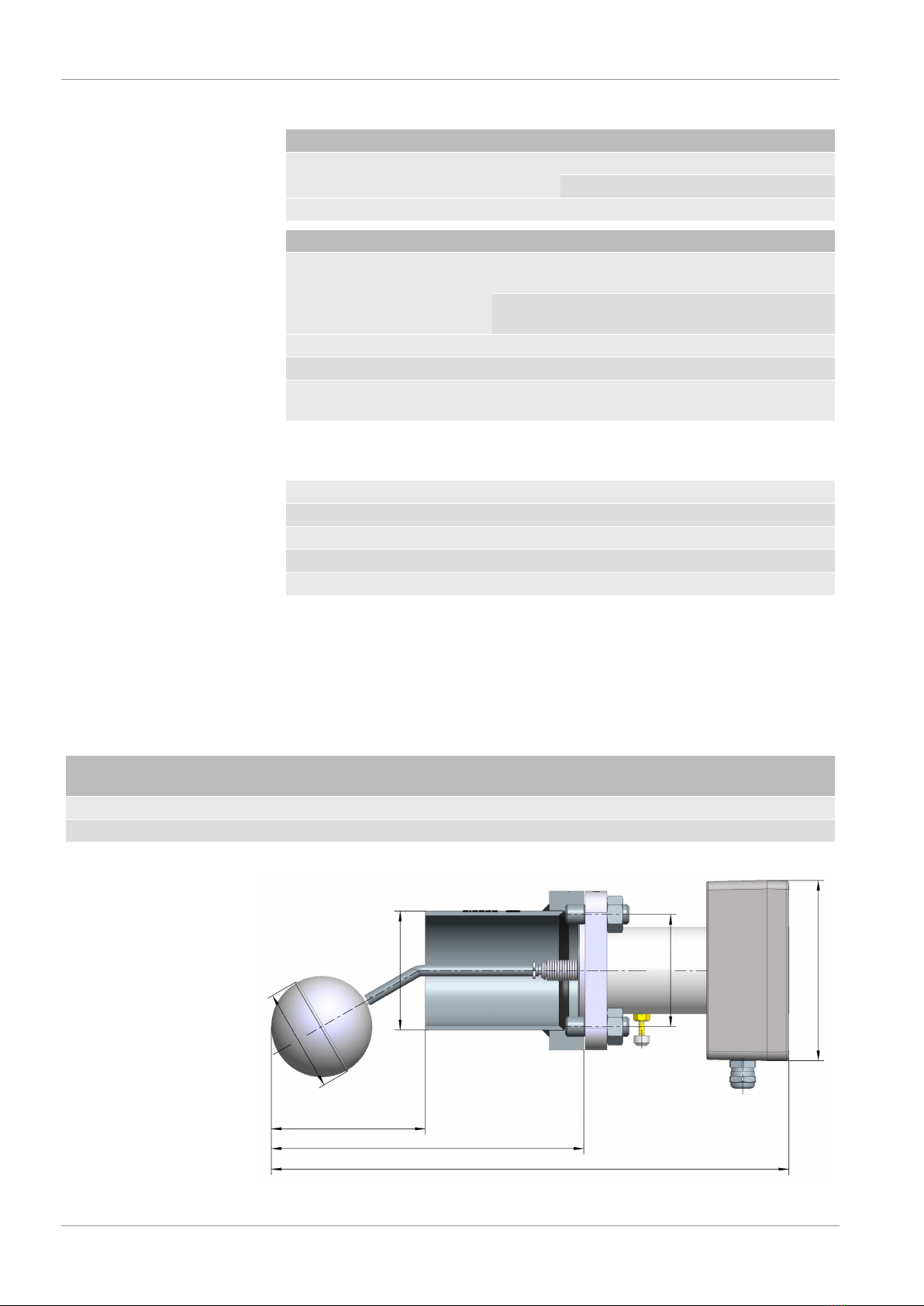
6.6.1 Dimensional drawings
All dimensions in mm unless otherwise stated
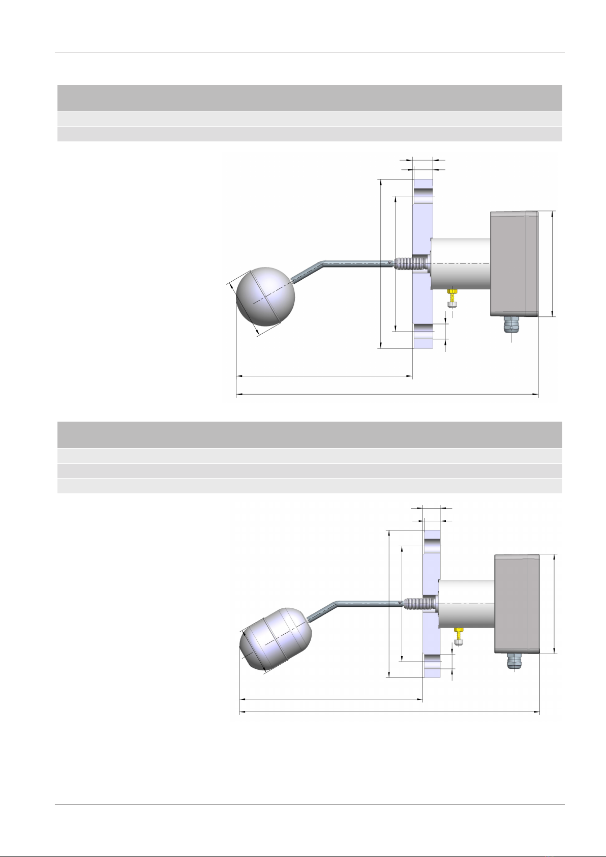
6.6.1.1 Version with welding connection
Version Flange
material
ABC
[Ø]
D
[square]
e
NK104 1.0425 P265GH 213 359 82.5 77.8 x 77.8 107
NK105 1.0425 P265GH 250 396 88.9 90.0 x 90.0 105
A
B
125
D
C
Ø72
E
Fig.3: Dimensional picture NK104 NK105
FISCHER Mess- und Regeltechnik GmbH Technical data | 6
BA_EN_NK10 13 / 28
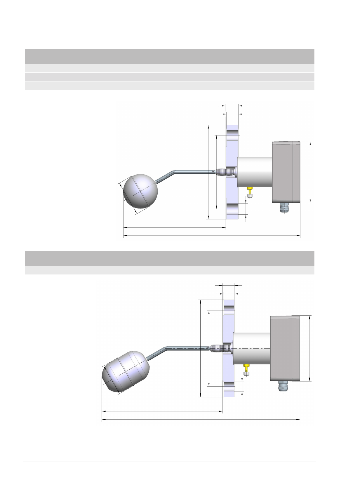
6.6.1.2 Flange DIN EN 1092-1 Type B1
Version Flange
material
Port D
[Ø]
LK
[Ø]
B b d
[Ø]
No. of
holes
NK102 1.0425 P265GH DN80 PN40 200 160 24 22 18 8
NK10G 1.4571 --- DN80 PN40 200 160 24 22 18 8
209
359
125
B
b
d
D
LK
Ø72
Fig.4: Dimensional picture NK102 NK10G
Version Flange
material
Port A D
[Ø]
LK
[Ø]
B b d
[Ø]
No. of
holes
NK101 1.0425 P265GH DN65 PN40 230 185 145 22 20 18 8
NK103 1.0425 P265GH DN65 PN16 234 185 145 18 16 18 4
NK107 1.4571 --- DN65 PN40 230 185 145 22 20 18 8
379
125
B
b
d
D
LK
Ø62
A
Fig.5: Dimensional picture NK101 NK103 NK107

6 | Technical data FISCHER Mess- und Regeltechnik GmbH
14 / 28 BA_EN_NK10
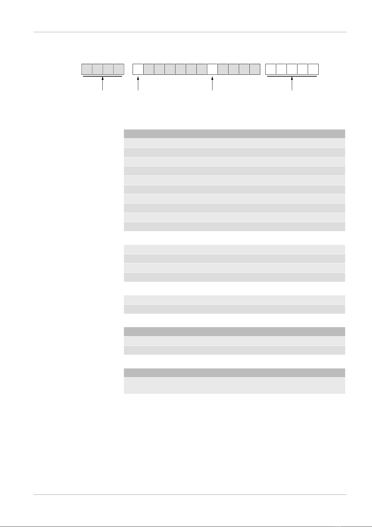
6.6.1.3 Flange DIN EN 1092-1 Type C
Version Flange
material
Port D
[Ø]
LK
[Ø]
B b d
[Ø]
No. of
holes
NK10F 1.0425 P265GH DN80 PN40 200 160 24 19.5 18 8
209
359
125
Ø72
D
LK
Ø120
Ø106
d
B
b
Fig.6: Dimensional picture NK10F
Version Flange
material
Port A D
[Ø]
LK
[Ø]
B b d
[Ø]
No. of
holes
NK106 1.0425 P265GH DN65 PN40 230 185 145 22 17.5 18 8
NK10A 1.0425 P265GH DN65 PN16 234 185 145 18 13.5 18 4
B
b
379
125
d
D
LK
Ø109
Ø95
Ø62
A
Fig.7: Dimensional picture NK106 NK10A

FISCHER Mess- und Regeltechnik GmbH Technical data | 6
BA_EN_NK10 15 / 28
6.6.1.4 Flange DIN EN 1092-1 Type G
Version Flange
material
Port D
[Ø]
LK
[Ø]
B b d
[Ø]
No. of
holes
NK10H 1.4571 --- DN80 PN40 200 160 24 22 18 8
B
b
209
359
d
D
LK
Ø106
125
Ø72
Fig.8: Dimensional picture NK10H
6.6.1.5 Flange DIN EN 1092-1 Type D
Version Flange
material
Port D
[Ø]
LK
[Ø]
B b d
[Ø]
No. of
holes
NK10B 1.0425 P265GH DN65 PN40 185 145 22 20 18 8
230
279
125
B
b
d
D
LK
Ø110
Ø94
Ø62
4
Fig.9: Dimensional picture NK10B
6 | Technical data FISCHER Mess- und Regeltechnik GmbH
16 / 28 BA_EN_NK10
6.6.1.6 Flange ANSI B16.5
Version Flange
material
Port A D
[Ø]
LK
[Ø]
B b d
[Ø]
No. of
holes
NK10K 1.0425 P265GH 3‘‘ 150 lbs 209 192.5 152.4 24 22.8 19.1 4
NK10N 1.0425 P265GH 3‘‘ 300 lbs 204 209.5 168.1 28.4 26.8 22.3 8
NK10P 1.0425 P265GH 4‘‘ 300 lbs 201 254 200.1 31.7 30.1 22.3 8
359
B
b
d
125
D
LK
Ø72
A
Fig.10: Dimensional picture NK10K NK10N NK10P
Version Flange
material
Port A D
[Ø]
LK
[Ø]
B b d
[Ø]
No. of
holes
NK10M 1.0425 P265GH 2.5‘‘ 300 lbs 227 190.5 149.3 25.4 23.8 22.3 8
B
b
359
d
D
LK
125
Ø62
A
Fig.11: Dimensional picture NK10M
FISCHER Mess- und Regeltechnik GmbH Order Codes | 7
BA_EN_NK10 17 / 28
7 Order Codes
0 0
Switching
elements
N K 1 0
Type
Flange
000 00000
1 2 5 6 7 8 9 10 11 123 4Code no. 13 14 15 16 17
Optional information
e.g. SIL
[1] Flange material
1DIN EN 1092-1 Form B1 DN 65 PN40 1.0425 P265GH
2DIN EN 1092-1 Form B1 DN 80 PN40 1.0425 P265GH
3DIN EN 1092-1 Form B1 DN 65 PN16 1.0425 P265GH
7DIN EN 1092-1 Form B1 DN 65 PN40 1.4571 ---
gDIN EN 1092-1 Form B1 DN 80 PN40 1.4571 ---
6DIN EN 1092-1 Form C DN 65 PN40 1.0425 P265GH
ADIN EN 1092-1 Form C DN 65 PN16 1.0425 P265GH
FDIN EN 1092-1 Form C DN 80 PN40 1.0425 P265GH
BDIN EN 1092-1 Form D DN 65 PN40 1.0425 P265GH
hDIN EN 1092-1 Form G DN 80 PN40 1.4571 ---
KANSI B16.5 3‘‘ 150 lbs 1.0425 P265GH
CANSI B16.5 2.5‘‘ 300 lbs 1.0425 P265GH
NANSI B16.5 3‘‘ 300 lbs 1.0425 P265GH
PANSI B16.5 4‘‘ 300 lbs 1.0425 P265GH
4Welding connection 82.5 mm (S80)
5Welding connection 88.9 mm (S90)
[8] Switching Elements
11 micro-switch
22 micro-switch
[13-17] Optional information
##### Code for special models e.g. SIL
The code is generated as agreed with our sales team.
8 | Attachments FISCHER Mess- und Regeltechnik GmbH
18 / 28 BA_EN_NK10
8 Attachments
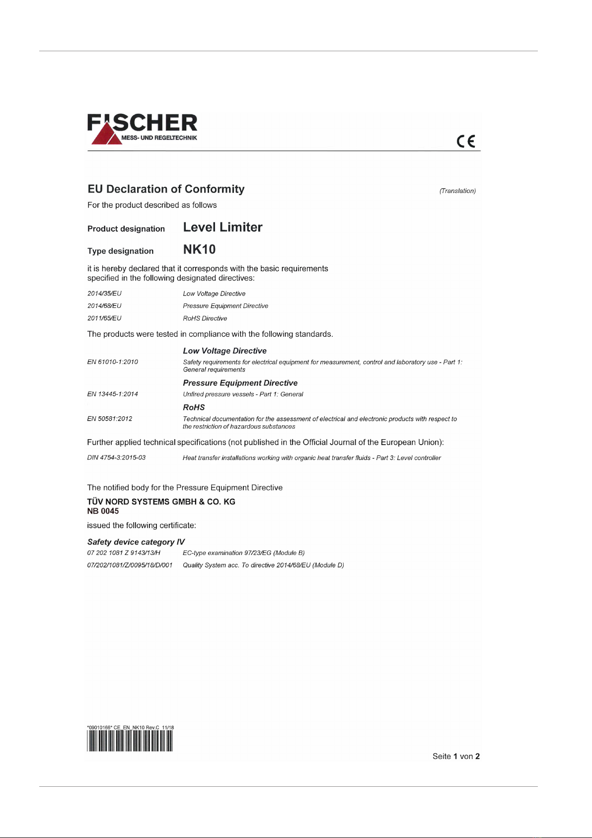
8.1 Declarations of conformity
Fig.12: CE_DE_NK10 part1
FISCHER Mess- und Regeltechnik GmbH Attachments | 8
BA_EN_NK10 19 / 28
Fig.13: CE_DE_NK10 part2
8 | Attachments FISCHER Mess- und Regeltechnik GmbH
20 / 28 BA_EN_NK10
8.2 Type testing certificates
8.2.1 Pressurised Vessel Directive 2014/68/EU
0
YNO
ZERTIFIKAT
CERTIFICATE
I )
I
I
B)
&
TÜV &
�
Fig.14: BMP_97-23-EG_DE_EN
This manual suits for next models
16
Table of contents
Other FISCHER Industrial Electrical manuals

Popular Industrial Electrical manuals by other brands


Pilz
Pilz PSS SB PASSIVE JUNCTION operating instructions

Murata
Murata GRM022R61A102ME19 Series Reference sheet

Moeller
Moeller NZM-XCM installation instructions

Murata
Murata GRM155R60J103KA01 Series Reference sheet

Moeller
Moeller NHI-NZM 14 Series installation instructions

ABB
ABB ACS880-604 Hardware manual