FISCHER 225 User manual

Barograph User’s Manual
MMM
M
M
M
M
M
M
aaa
a
a
a
a
ddd
d
d
d
d
eee
e
e
iii
n
n
n
n
n
GGG
G
G
G
G
G
ee
e
e
e
e
r
r
r
r
r
r
mm
m
m
m
m
aa
a
a
a
nn
n
n
n
y
y
yy
y
p
p
p
p
p
p
p
r
r
r
r
rr
r
e
e
e
e
e
e
e
e
s
s
s
e
e
e
e
e
e
e
e
n
n
n
n
n
n
n
t
t
t
t
e
e
e
e
e
e
e
e
e
e
d
d
d
d
d
b
b
b
b
b
b
b
b
b
b
b
b
y
y
y
y
y
y
y
y
y
y
y
y

English Edition
Copyright ©, 2011 Feingeratebau K. Fischer GmbH (Germany)
Feingerätebau K.Fischer GmbH
Venusberger Straße 24
D-09430 Drebach
Germany
Tel +49 (0) 37341 / 487-0
Fax +49 (0) 37341 / 487-30
Email [email protected]
Internet www.meteoclima.de
Fischer USA
3050 NW 63rd St
Seattle, WA 98107
USA
Tel +1 206-783-1414
Fax +1 206-783-9209
Email [email protected]
Internet www.scherbarometers.com

®
Barograph User’s Manual

~ 4 ~
®
Barograph User’s Manual
Table of Contents
1. General Information.....................................................................................5
2. About Barographs........................................................................................5
2.1 Mechanical Diagram.............................................................................6
2.2 Technical Data...................................................................................... 7
2.3 Model Specications ............................................................................ 8
3. Unpacking the Barograph..........................................................................10
4. Start Up ..................................................................................................... 11
4.1 Setting the Drum Revolution Cycle .................................................... 11
4.2 Mechanical Clockwork........................................................................ 12
4.3 Quartz Clockwork .............................................................................. 13
4.4 Starting the Barograph .......................................................................14
5. Maintenance..............................................................................................15
5.1. Winding the Mechanical Clockwork................................................... 15
5.2. Changing the Battery.........................................................................15
5.3. Replacing the Chart Paper................................................................16
5.4 Setting the correct local pressure....................................................... 17
5.5 Cleaning the Housing.........................................................................17
5.6 Troubleshooting.................................................................................. 18
6. EEC Conformity.........................................................................................19
7. Liability Limitations ....................................................................................20
Appendix 1. Pressure Corrections for Elevation............................................21
~ 5 ~
®
Barograph User’s Manual
1. General Information
This manual contains important information about the function, start-up, and maintenance of Fischer
Barographs. Please review all of the information before initial use of the barograph. For the barograph
to function as intended, all instructions in this manual must be followed in detail. If the instructions are
not followed closely, operational malfunctions may occur.
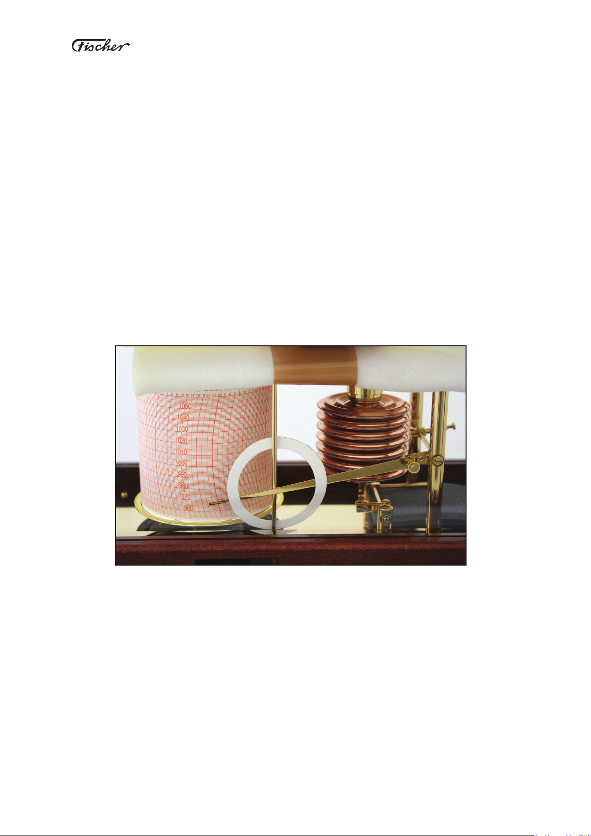
2. About the Barographs
Fischer barographs record changes in atmospheric pressure over time. The measuring element
used is a 7-cell aneroid capsule set with a 62-mm diameter. They are constructed from a corrosion-
resistant copper-beryllium alloy whose excellent exibility has made it the best material for measur-
ing atmospheric pressure for the past 70 years. These aneroid capsules are essentiality immune to
hysteresis and elastic after-effects.
The effect of temperature changes on the measurement is compensated for with bimetal elements
over the full range of pressures for temperatures between -30° C (-22° F) and 40° C (104° F).
The elements of the precision movement are made of brass in various nishes, depending on the
model. All crucial axles use jeweled bearings for lowest possible residual friction. All materials used
are corrosion-resistant. The measuring element is enclosed within the fully ventilated housing and is
therefore protected from mechanical damages. Optional lockable housings are also available. Some
models employ an enhanced dampening movement for use at sea.
All standard barograph models have optional pressure ranges that are selected before purchase to
match the station elevation where they will be used, but the models with enhanced dampening are as-
sumed to be used at sea, so they come with a single xed pressure range for sea-level applications.
The barographs are equipped with either a mechanical or quartz clockwork that drives the rotation of
the recording drum.
For the quartz clockworks, the drum revolution can be easily set to a daily, weekly, or monthly cycle.
The corresponding time in hours would be 25.6 hr, 176 hr, and 783 hr respectively.
The mechanical clockworks can be changed between daily or weekly operation.
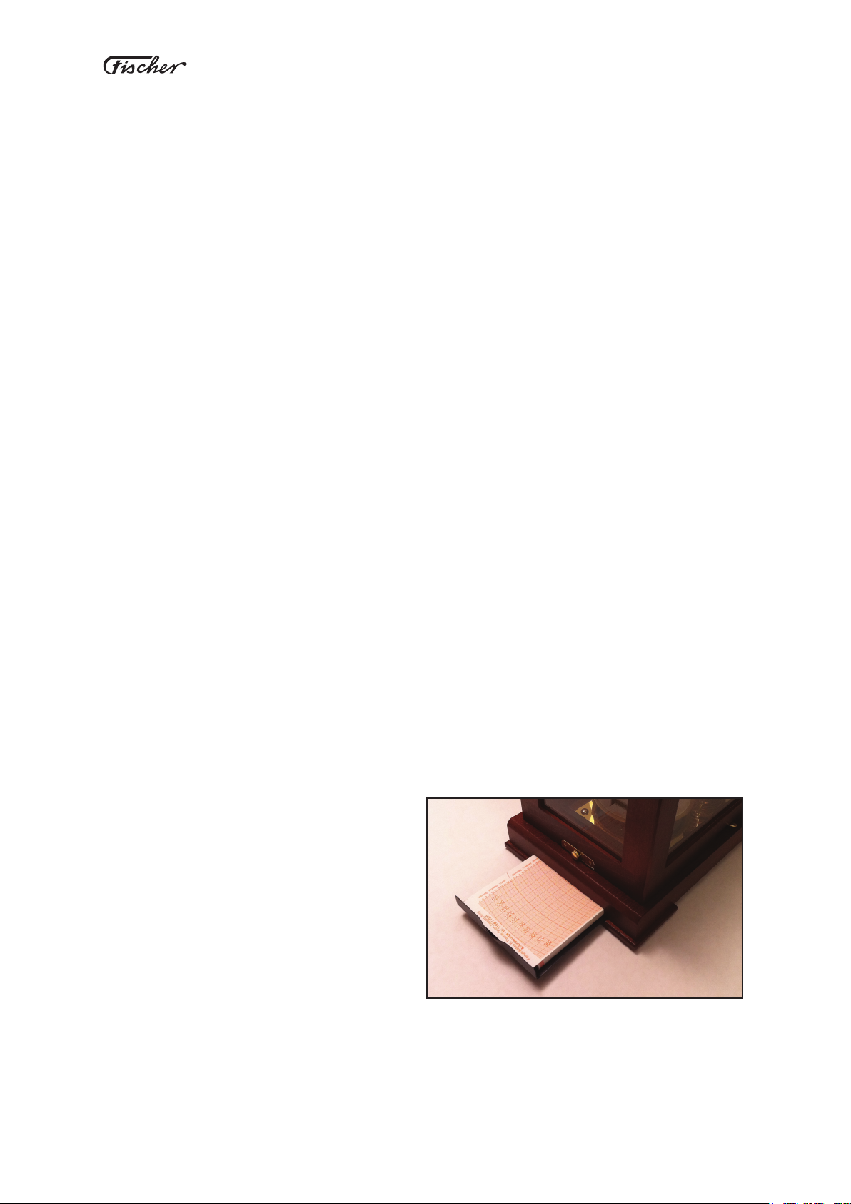
All models of barographs come with ber pens
and chart paper to last one year. The Captain
and Admiral models have a chart storage tray
built into them. The Captain model is accessed
from the end of the unit; the Admiral model from
the side.
Chart tray on Captain’s Choice model

~ 6 ~
®
Barograph User’s Manual
2.1 Mechanical Diagram
1. Precision Movement
2. Socket
3. Grub screw set
4. Pressure adjustment screw
5. Upper telescope case
6. Lower telescope case
7. Capsule set
8. Pin
9. Bimetal arm
10. Axle
11. Transport mode screw
12. Null-setting lever
19
4
21
5
6
7
20
21
18 15 17
16 14 3
11
13
22
12
10
23
X
8
9
24
13. Housing lock
14. Disengaging rod release
15. Pen-arm
16. Fiber pen
17. Disengaging rod
18. Clockwork
19. Fastening nut
20. Recording drum
21. Diagram retaining strips
22. Housing
23. Handle
24. Pen-arm adjustment screw

~ 7 ~
®
Barograph User’s Manual
2.2 Technical Data
Accuracy of measurement ±0.7 hPa (mb)
Chart graduation 1 hPa (mb)
Measuring range corresponding altitude
955 to 1055 hPa 0 up to 150 m above sea level ( 0 to 490 ft)
930 to 1030 hPa 150 up to 350 m above sea level ( 490 to 1,150 ft)
905 to 1005 hPa 350 up to 600 m above sea level (1,150 to 1,970 ft)
880 to 980 hPa 600 up to 850 m above sea level (1,970 to 2,790 ft)
855 to 955 hPa 850 up to 955 m above sea level (2,790 to 3,140 ft)
Clockwork
Mechanic drum clockwork: International accuracy standard DIN 58658
Revolution cycle day = 25.8 h
week = 176 h
Running period 1 week (see later notes on clockwork)
Electronic quartz clockwork
Revolution cycle day = 25.8 h
week = 176 h
month =783 h
Running period 12 months (uses two AA 1.5 V batteries)
Recording drum
Drum material: plastic
Drum dimensions: 93.3 mm diameter, 93 mm high
Chart paper clamp material: brass nickel plates
Chart paper write range 80 mm; resolution 1 hPa (inches charts also available)
Materials
Transmission system: brass matte-chromium-plates, axles in chrome-plated steel
Movement stand: aluminium (2S5/267M Brass polishes)
Housing cover part : 225 / 227 aluminium and chrome-plated steel X5CrNi1810,
corrosion resistant, other models, polished wooden cases
Accessories
Additional chart paper
Sealed pack of 2 ber pens
AA Batteries (Quartz Models)
Carrying Case ES-55 (for Models 225/227)
~ 8 ~
®
Barograph User’s Manual
2.3. Model Specications
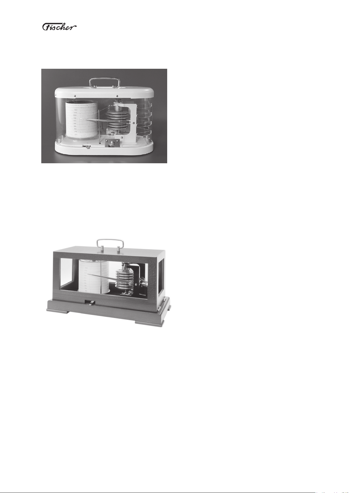
“Navigator’s Choice” Models 225, 227
Housing made of cast aluminum and chrome steel,
with a white nish. Movement brass and steel, with
at chrome nish. Glazing made of transparent
synthetic material.
Dimensions 290 x 145 x 190 mm
(11.4” x 5.7” x 7.5”); weight 2.5 kg (5.5 lbs)
Model 225 Mechanical wind-up clockwork. Runs in
2 modes: daily or weekly.
Model 225Q Quartz clockwork. Runs in 3 modes: daily, weekly, and monthly.
Optional pressure ranges selected at time of purchase.
Model 227 and 227Q same as above with vibration-damped movement for use at sea, with a xed
measuring range of 955 - 1055 hPa.
“Captain’s Choice”
Models 205M, 207M and 285M, 287M
Housing made of beech hardwood with a mahog-
any stain nish. Comes with choice of movement
nishes.
Dimensions 345 x 170 x 180 mm
(13.6” x 6.7” x 7.1”); weight 3.4 kg (7.5 lbs)
Model 205M Mechanical wind-up clockwork. Runs in 2 modes: daily or weekly.
Movement brass and steel, with at chrome nish.
Model 205MQ Quartz clockwork. Runs in 3 modes: daily, weekly, and monthly.
Movement brass and steel, with at chrome nish.
Model 285M, 285MQ same as above with polished brass movement.
Optional pressure ranges selected at time of purchase.
Model 207M, 207MQ and 287M, 287MQ same as above. With vibration-damped movement for use at
sea, with a xed measuring range of 955 - 1055 hPa.

~ 9 ~
®
Barograph User’s Manual
“Admiral’s Choice” Models 265, 267
Housing made of beech hardwood with a
mahogany stain nish. Glazing cut glass with
beveled edges. Base plate and movement of
polished brass; includes front drawer for charts
and pens.
Dimensions 345 x 190 x 185 mm
(13.6” x 6.7” x 7.1”); weight 4.4 kg (9.7 lbs)
Model 265M Mechanical wind-up clockwork. Runs in 2 modes: daily or weekly.
Model 265MQ Quartz clockwork. Runs in 3 modes: daily, weekly, and monthly.
Optional pressure rages selected at time of purchase.
Model 267M and 267MQ same as above With vibration-damped movement for use at sea with a xed
measuring range of 955 - 1055 hPa.
~ 10 ~
®
Barograph User’s Manual
3. Unpacking the Barograph
After taking the barograph out of it’s packaging, remove the surrounding paper, including the carrier-
handle cardboard wrap.
Warning: Be sure to remove all accessories (chart paper, ber-pens, battery, and clock-
work key) from the package before discarding it.
To open the housing, move the housing lock (13) to the left and raise the lid. For models 225/227
move the housing lock to the left and right.
In models 225 and 227 (Navigator’s Choice) both sides of the housing can be opened.
The barographs are initially set to transport mode. The housing is locked and the transmission system
is decoupled in two places. (This does not apply to the 2X7 series with vibration-damped measuring
systems). The pen-arm is also secured to the disengaging rod with a circular cardboard clip.
Before starting the barograph, the transmission system must be reconnected as shown, and the write-
arm must be removed from the cardboard clip.

~ 11 ~
®
Barograph User’s Manual
4. Start Up
The following instructions will prepare you for the initial start up of the barograph including setting the
drum revolution cycle, winding the mechanical clockwork or setting the quartz clockwork, and begin-
ning recording.
4.1. Setting the Drum Revolution Cycle
The clockwork is located inside the recording drum, which it rotates in a clockwise direction. The
clockwork can be set for 1 day (daily), 7 day (weekly), or 31 day (monthly) revolution cycle.
Warning: The monthly setting is only available with quartz clockwork models. The baro-
graphs are initially set to a weekly cycle. To change the setting you must lift the record-
ing drum off of the clockwork as described in the following sections.
Connect the decoupled pieces
by inserting the pins in the
slots provided. The weight
of the pen-arm will keep it in
place.
~ 12 ~
®
Barograph User’s Manual
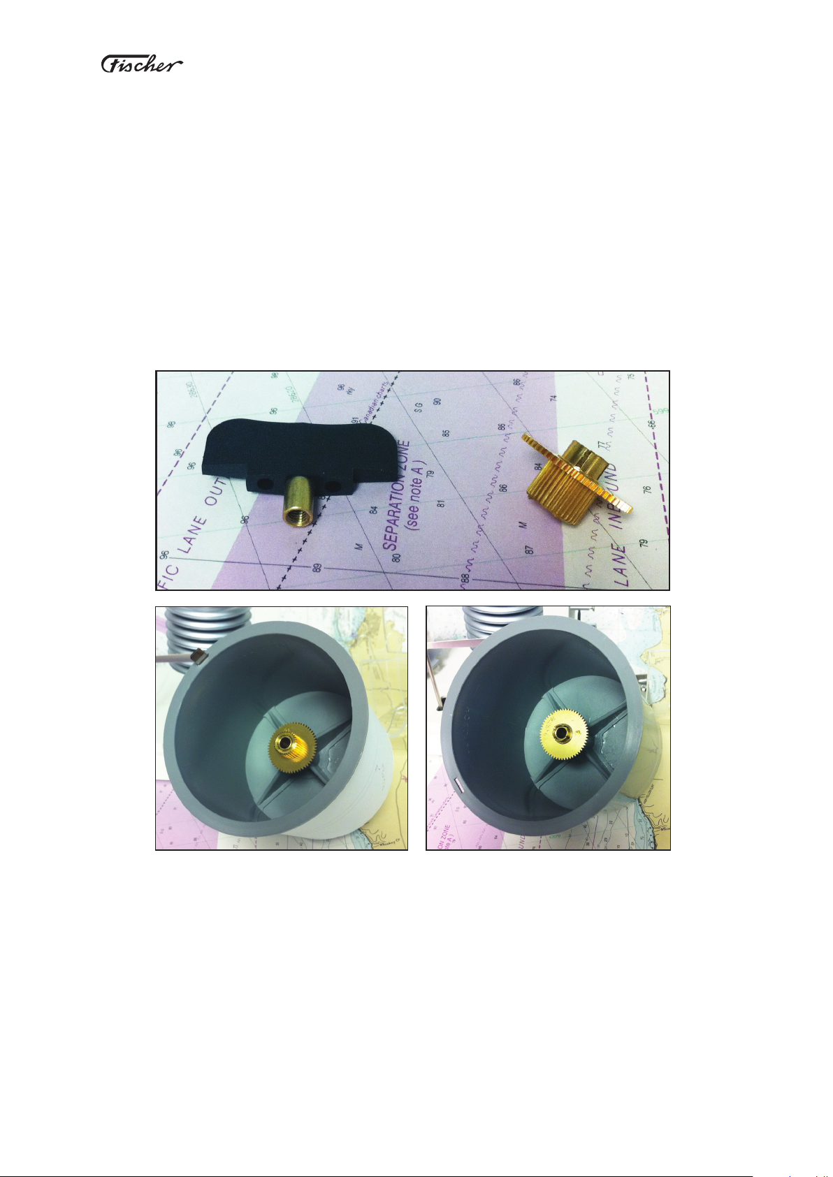
:HHNO\ Orientation 'DLO\ Orientation
Clockwork Key
Gear Wheel
4.2. Mechanical Clockwork
To remove the drum, insert the clockwork key in the drum and turn the key in a clockwise motion. Us-
ing both hands, place ngers underneath the edge of the drum and lift it off the clockwork. After that,
the revolution cycle can be set by inserting the gear wheel in the desired orientation (daily or weekly).
Then replace the drum over the clockwork, and using the key, screw it back down in a counter-clock-
wise motion.
To start the mechanical clockwork, wind the clockwork key in a counter-clockwise motion until it is
fully wound — until it will turn no further. This will be about 9 or 10 full 360° turns of the key.

~ 13 ~
®
Barograph User’s Manual
4.3. Quartz Clockwork
Using both hands, place ngers underneath the edge of the drum and lift it off the clockwork. After
that, the revolution cycle can be set by moving the red gear wheel to the desired position (daily,
weekly, or monthly). The highest position is 7 day (weekly), the middle position is 31 day (monthly)
and the lowest is 1 day (daily).
Warning: After changing the drum revolution cycle you will need to insert the corre-
sponding chart paper. Standard delivery includes weekly charts, but this can be changed
at the time of purchase.
To start the electronic quartz clockwork, simply insert the provided AA battery into the battery holder.
Be sure that the positive and negative ends are in their correct positions. After the battery is in place,
put the recording drum back on the clockwork.
Daily Position
Monthly Position
Weekly Position
Daily
Weekly
Monthly
~ 14 ~
®
Barograph User’s Manual
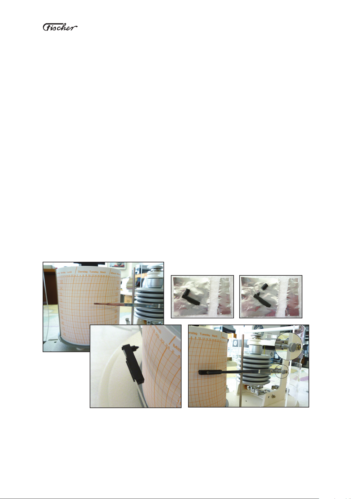
4.4. Starting the Barograph
For instructions on attaching the chart paper see section 5.3 Replacing the Chart Paper.
The Barographs are supplied with two ber pens. Each pen should last 6 to 8 months under normal
usage. To insert a new pen, remove the protective tip of the ber pen and attach it to the pen-arm as
shown in the illustrations. Before recording, be sure that the proper chart paper is being used in ac-
cordance with the drum revolution cycle. Adjust the pen-arm’s position using the Pen-arm Adjustment
Screw until the ber pen touches the chart paper on the recording drum.
Note: This should be set to have the minimum force on the chart that will leave a trace.
You can rotate the drum manually to check this. Too much pressure could mask small
pressure changes.
Then close and lock the housing and the barograph is ready to begin recording.
If desired, the safety lock on the housing can be engaged to prevent unauthorized access to the baro-
graph.
Be sure the pen-arm is not touching the disengagement rod when recording pressures.
Pen-arm Adjustment Screw (inset)

~ 15 ~
®
Barograph User’s Manual
5. Maintenance
The following instructions will detail the proper maintenance procedures to insure that the barograph
functions to its full potential.
5.1. Winding the Mechanical Clockwork
The mechanical clockwork can last on its own for at least 1 week. After that the clockwork must be re-
wound in its entirety. From a fully unwound position, this will take approximately 10 full 360° turns.
Warning: The clockwork must always be wound in a counter-clockwise motion, other-
wise the clockwork could be irreparably damaged.
5.2. Changing the Battery
The electronic quartz clockwork runs approximately 12 months. The actual life of the battery will de-
pend upon the chosen drum cycle revolution setting as well as operating conditions. If the clockwork
stops replace the battery. Always use AA batteries.

~ 16 ~
®
Barograph User’s Manual
5.3. Replacing the Chart Paper
At the end of the drum revolution cycle, move the pen-arm away from the drum using the lever at-
tached to the Disengaging rod (see section 2.1 Mechanical Diagram). Then remove the recording
drum from the clockwork. Remove the clamp holding the chart paper to the recording drum and re-
move the used chart paper. Wrap a new chart paper around the drum so that the slightly overlapping
edges line up with the location of the clamp (see diagram 5.3). Be sure that the bottom (low pressure)
side of the chart paper is lined up directly with the lip on the lower edge of the recording drum. Insert
the clamp in the slot at the base of the drum and clip it at the top.
After the paper is loaded, replace the drum on the clockwork with the time and date approximately
aligned with the pen position. Once the chart is in place and the pen is returned to the chart, make a
nal manual rotation of the drum to the correct time as needed. This may take a further adjustment
after some time has passed to remove slack in the gear.
Warning: If the barograph has a mechanical clockwork, the clockwork key must be unscrewed (in the
clockwise direction) before removing the recording drum. Likewise it must be screwed back in (coun-
ter-clockwise) after it the drum has been replaced.

~ 17 ~
®
Barograph User’s Manual
5.4 Setting the correct local pressure
Your barograph will provide accurate pressures to within ± 0.7 hPa, but it is best to check the pres-
sure at rst installation and adjust the pen position as needed. Local airports or weather services
offer pressure values as do some newspapers. There are also numerous convenient online sources
of local weather data. See in particular www.starpath.com/barometers which is set up specically to
provide you with accurate local pressure worldwide, as well as elevation corrections.
Recall that most public sources of accurate pressure are corrected to sea level pressure, which will
be higher than the actual pressure at your instrument location unless you too are at sea level.
Thus to set your barograph to the correct local pressure, called station pressure, you must reduce the
reported sea level pressure for your location by an amount determined by the elevation of your loca-
tion plus the height of the instrument above ground level. See Appendix 1.
The Pressure adjustment screw is located above the measuring elements, as shown in Section 2.2.
There is a small lock screw on top of it that must be released before the adjustment and then gently
tightened once done.
Warning: The pressure range of the barograph, from top to bottom of the chart, cannot
be changed without irreparably damaging the instrument. Therefore the pressure range
adjustment screws have been secured with lacquer and should not be adjusted.
5.5 Cleaning the Housing
The outside of the housing can be cleaned with a dampened washcloth and mild soap. Do not under
any circumstances use scrubbing agents or solvents.
~ 18 ~
®
Barograph User’s Manual
5.6 Troubleshooting
Error Possible Cause Solution
The barograph is not
recording
The ber pen is not touching the
recording drum. Move lever to the right.
The protective case has not been
removed from the ber pen. Remove the protective case.
The ber pen has dried up. Dampen the pen with a drop of
vinegar.
The ber pen is used up. Change pen.
The recording drum
does not rotate
The recording drum is not set on the
clockwork axle properly.
Gently rotate the drum until you
feel the gears engage.
The clockwork has not been prop-
erly wound. Fully wind the clockwork.
Gears are not engaged properly. Reset the drum revolution cycle,
paying close attention to the gears
Battery is dead. Change battery.
The barograph records
a constant pressure
The pen-arm is touching the Disen-
gaging rod. Press lever completely to the right.
Time measurements
on the chart paper do
not correspond with the
rotation of the recording
drum
The wrong chart paper is being
used.
Make sure the chart paper cor-
responds with the drum revolution
cycle.
The battery is dying. Change battery.
The barograph is
recording the wrong
values
The chart paper used does not
correspond with the range of the
barograph.
Make sure you are using the cor-
rect chart paper.
The chart paper is not correctly
aligned.
Reset chart paper making sure the
bottom edge is properly aligned
with the base of the recording
drum.
Pressure correction not set. Correct the pressure adjustment.
Pressure correction drifted. Correct the pressure adjustment.
The barograph pen-arm
hangs down
The precision movement is not con-
nected to the pen-arm.
Reconnect the arm with the move-
ment (see Start up notes).

~ 19 ~
®
Barograph User’s Manual
6. EEC Conformity
We hereby conrm that the barographs series 205/207, 225/227, 215/217, 265/267, 285/287 conform
to the following regulations:
EEC guideline on electromagnetic compatibility 89/336/EWG as modied by guideline 92/31/EWG.
Further EU guidelines have not been established for the equipment.
The following standards are met for industrial and residential areas relating to protection from electro-
magnetic emissions and interferences.
EN50081-1:92/-2:93
EN50082-1:92/-2:95
All units carry the CE approval.

~ 20 ~
®
Barograph User’s Manual
7. Liability Limitations
No liability is assumed by Feingeratebau K.Fischer GmbH for damages and/or Injury resulting from
use of equipment supplied by this company. In no event will Feinieritebau K. Fischer be liable for
indirect or consequential damages whatsoever resulting from loss of use, data or prots arising out of
connection with the use or performance of Feirtgeritebau K. Fischer products.
Feingeratebau K. Fischer products are not designed, intended, or authorized for use as components
of medical systems, or other applications intended to support or sustain life, or for any other applica-
tion in which the failure of the Feingeratebau K. Fischer product(s) could create a situation where
personal Injury or death may occur. Any claims against Feingeratebau K. Fischer in connection with
the products described in this manual can exclusively be based on the guarantees provided. Any
further claims are excluded. In particular Feingeritebau K. Fischer does not give any guarantee as to
the correctness of the contents of this manual.
Feingeratebau K. Fischer reserves the right to make changes to their products and to their specica-
tions any time without prior notice.
Copyright ©, 2011 by Feingeratebau K. Fischer GmbH (Germany)
Operating manuals are subject of copyright. Copying, duplication, translation, conversion
into any electronic medium or any machine readable form, as a whole or in parts, is not
permitted.
This manual suits for next models
13
Table of contents
Other FISCHER Weather Station manuals


