Fisher Labs TW-7700 User manual
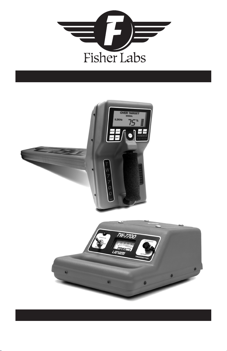
TW-7700
Operating Manual
FISHER RESEARCH LABORATORY
Digital Line Tracer

Description.............................................................................. pg. 3
Transmitter ............................................................................ pg. 4
Receiver ................................................................................... pg. 5
Accessories.............................................................................. pg. 7
Operating Instructions ........................................................ pg. 8
Depth Accuracy...................................................................... pg. 9
Specications ......................................................................... pg. 10
Using Headphones................................................................. pg. 11
Treasure Hunter’s Code of Ethics ..................................... pg. 11
CONTENTS

DESCRIPTION
1
3
The TW-7700 Digital Line Tracer consists of a transmitter, receiver,
ground-plate/ground-rod assembly, carrying case (hard or soft),
and
an operators manual. The TW-7700 is a single frequency line
tracer.
The TW-7700 is an active locating line tracer. There
are three methods of active locating that an operator
can use to trace a utility. The conductive method is
the most preferred method, since a strong transmit-
ter signal is transmitted through the intended target.
The inductive method is the easiest method to use,
but may not yield the best results. When a direct
connection is not available, but the operator has good
knowledge of where one point of the utility may be,
the operator can place the Transmitter over the utility
making sure that the arrow on top of the transmitter
is parallel to the path of the utility. The third method
of active locating involves using the coupling clamp
accessory. The coupling clamp is used when the utility
is exposed, but a direct connection is not available. The
clamp jaws are opened and placed around the utility.
The clamp never makes a direct connection with the
utility, that is, the utility can move freely with the
clamp around it.
The features of the TW-7700 make it a very easy and
practical instrument in today’s world of underground
locating.
4
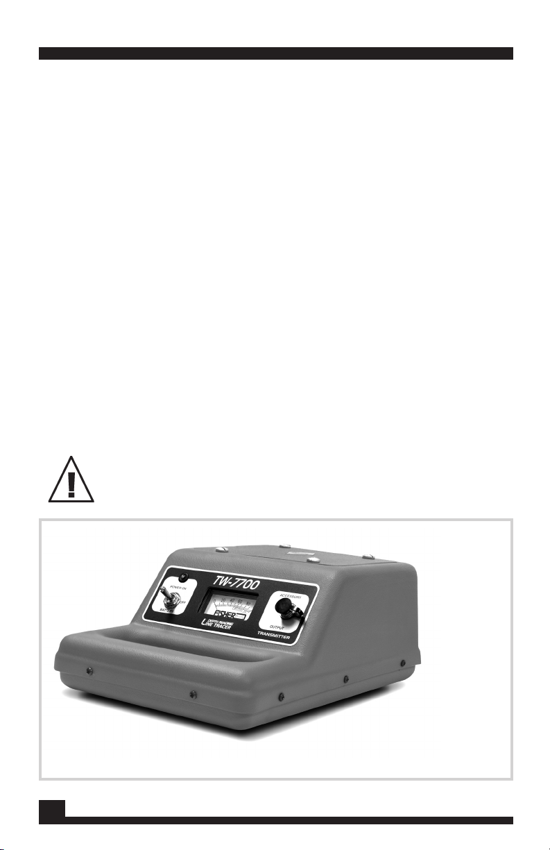
TW-7700 TRANSMITTER
Transmitter
WARNING:
Do not handle output leads unless power is off.
ELECTRIC SHOCK HAZARD:
Servicing to be performed by
qualied personnel only.
Located on the transmitter are the power mode and
the accessory output. The power mode enables the
operator to turn the transmitter on or off, and to
check the condition of the batteries. When checking
the batteries, a reading if 50 or greater on the dis-
play meter indicates that batteries are usable.
The accessory output is for the ground plate/ground
rod assembly, and for the coupling clamp. There is
a Red LED light that blinks when the transmitter
is on. The batteries are located underneath a lid on
top of the transmitter housing.
The TW-7700 Transmitter.
5
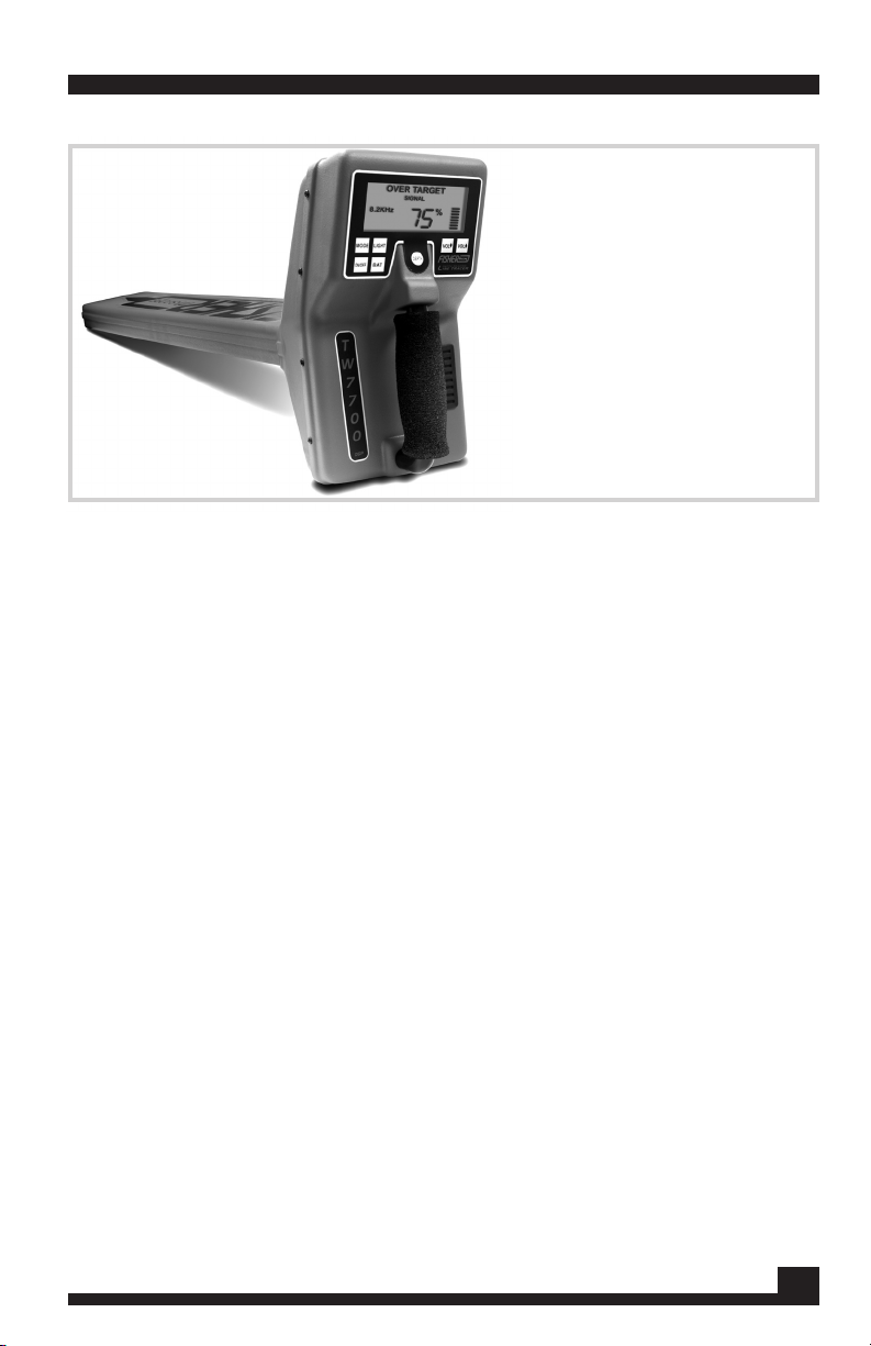
Receiver
Mode
This button does not have a function on the TW-7700. (It
allows users of the TW-8800 Multi-Frequency Line Tracer
to change frequencies.)
Power On/Off
Turns the receiver on or off.
Light
Lights up the display for usage in dark areas. When the
display is backlit, LIGHT is shown on the bottom left hand
side of the display screen.
Bat
Press and hold this pad to check the battery level of the
receiver. A bar graph on the right side of the display will
give status of the batteries. When the graph shows 1 bar, it
is time to replace the batteries. Additionally, as the opera
-
tor uses the Receiver, if the batteries get low, REPLACE
BATTERIES will appear in the lower area of the Display
screen.
Vol(up)/Vol(down)
Increases or decreases the volume of the speaker.
Depth
After determining the centerline of the utility, set the blade
of the receiver on the ground, press and hold this pad to get
the depth to the center of the target.
TW-7700 RECEIVER
Controls
WARNING: Do not handle output leads unless power is off.
ELECTRIC SHOCK HAZARD: Servicing to be performed by
qualied personnel only.
The TW-7700 Receiver.

6
TW-7700 RECEIVER
Frequency Modes
The frequency at which the receiver is operating.
<< Left/Over Target>/Right>>
Indicates where the receiver is in relation to utility.
Numeric Display
Serves a dual function:
•Relative signal strength of the transmitted signal (%
shown). Responds in conjunction with the bar graph.
•Depth to the center of the target (when DEPTH pad is
pressed - IN or CM shown)
Light
Indicates the display is lit (activated by pressing LIGHT pad).
Bar Graph
Serves three purposes:
•Responds in conjunction with signal strength.
•Visual indicator for battery test (when BAT pad is pressed).
•Volume loudness indicator (when VOL(up)/VOL(down)
is pressed.
Replace Batteries
When the receiver batteries fall below a nominal level, RE-
PLACE BATTERIES will be displayed.
No Signal
When no signal is received by the receiver, NO SIGNAL will
display. This response may be due to the transmitter not
being turned on, or the transmitter and receiver not be set
at the same frequency.
Display
7
ACCESSORIES
The coupling clamp is useful when the utility is exposed,
and a direct connection is not possible. It is plugged into
the same plug-in socket as the ground-plate/ground-rod
assembly. The coupling clamp only operates at the 82 kHz
frequency. The coupling clamp will t around utilities that
are 3-¼ inches in diameter or smaller. The length of the
cable is approximately 10 feet.
Coupling Clamp
Fisher Research Laboratory has a variety of headsets avail-
able.
•Ultra-quiet deluxe Fisher Phones. High quality sound
while reducing the outside noise.
•Standard Stereo Headphones
•Single Earpiece Headset. Enables the operator to effec-
tively listen to the TW-7700 and remain aware of noise in
close proximity.
Headsets
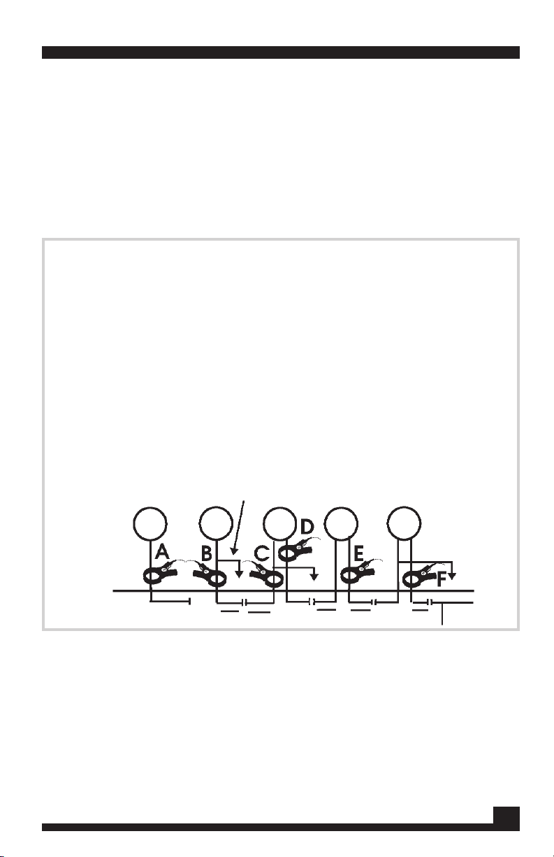
This represents a jumper
Coupling Clamp Applications Diagram
A. The coupling clamp is for all
tracing applications with conduc-
tors exposed; exception, an
open
circuit at line’s termination.
B. A ground must be provided
for the proper current ow when
the coupling clamp is used at a
termination.
C. The coupling clamp must be
used between the grounding
and where the line goes under-
ground.
D. Trace signal will return to ground
when incorrectly coupled.
E. Signal will be transmitted in both
directions when connect
ing is
midway in a long conductor.
F. Drop lines or laterals divide the
signal strength in half at each
junction.

Set-up Transmitter either Inductively or Conductively
Inductive
Be aware of air coupling, the transmitted signal travelling to
the Receiver via the air, not the utility.
Conductive
Connect the ground plate/ground rod assembly to the trans-
mitter. Connect the red lead to the non energized utility.
Connect the black lead to the ground plate/ground rod. Place
the plate/rod at a 90 degree angle in reference to the utility.
Be sure not to place the wires over any other utility.
After transmitter set-up, move away from the point of con-
nection (or Induction) about 25 feet (8 meters). Sweep a
circle around the point of connection. Initially, disregard
the LEFT/RIGHT indicator and rely on the signal strength
readout. Make note of the high readings. These are areas
that need to be traced/examined in more detail.
Tracing
After locating the point(s) where the signal strength was the
highest, return to that/those points and start tracing your util-
ity. This is where the LEFT/RIGHT indicator is very helpful.
Swing the receiver from left to right and listen for the change
of tone. When the target is to the RIGHT of the receiver, the
tone is pulsed tone. As the receiver gets closer to the target,
the pitch gets higher. When the target is to the LEFT of the
receiver, the tone is a continuous tone. As the receiver gets
close to the target, the pitch also becomes higher. When the
receiver is over the target, OVER TARGET is displayed on the
display screen, and the tone is at its highest peak sound.
Depth Measuring
When an OVER TARGET response is displayed, position
the blade of the receiver directly over the utility and place
the tip on the ground. Hold the receiver steady, press and
hold the DEPTH pad. Depth will be measured to the center
of the utility.
INITIAL SCAN
8
OPERATING INSTRUCTIONS
The following instructions are designed for a safe and effective
method of line tracing and utility avoidance. Some of the steps
may not be applicable in all situations. The underlying guide-
line is that operator safety must be maintained at all times. Use
of safety equipment, extra personnel, and up to date as-built
plans should be considered when necessary.

DEPTH ACCURACY
Depth measurement is a feature of the TW-7700. Accuracy
is dened on an ideal target, that is, one that is continuous, a
good conductor, and not surrounding by other utilities. There
are factors that can cause the operator to question the accu-
racy of the utility being traced.
Inductive Transmitter Setup
Inductively, only a small portion of the signal attaches
itself to the utility. With a weakened signal, trace should
be accurate, but depth may not. The conductive method
will yield better results.
Low Receiver Signal Strength
When the signal strength falls below 20 – 25%, depth read-
out may not be accurate. It would be benecial to move the
transmitter to a closer point of contact.
Nearby Utilities
Close, nearby utilities may have some inuence on the
accuracy of the Depth readout. This is more prone to hap-
pen in the higher frequencies where signals can jump to
nearby utilities. Switching to a lower frequency can give
better results.
Moisture
Ground that is too dry or overly saturated may skew the
depth readout.
“T’s”, elbows, or splits in the utility can distort the
transmitted signal in that general area.
9
WARNING: Do not connect output leads to a live
(energized) utility. Please prevent shock hazard and
equipment damage.

SPECIFICATIONS
Subject to improvement or modication without notice.
10
TRANSMITTER
RECEIVER
Depth Accuracy ........................+1 inch per foot in nominal conditions
Readout Units ..........................Inches or cm (factory preset)
Left/Right Guidance................. Audio: continuous tone=Left,
pulsed tone=Right. VCO (varying pitch) output for easy over
............................................target location. Visual: Left/Right/
............................................Over Target messages
Signal Strength ........................ Digital Numeric Readout (0-99%)
& Bar Graph
Sensitivity Adjust..................... Automatic
LCD Backlight.......................... Included
Battery Test..............................Automatic Low Battery alert
Push button readout
Battery Type............................. Six “C” cells
Battery Life ..............................80 Hours
Weight.......................................5.4 lbs.
Operating Temp .......................-4 0 to +1400F (-200to +600C)
Output Frequency.................... 82kHz,
Output Power (nominal) ...........5Watts,
Battery Test..............................Yes
Battery Type............................. Two 6 Volt lantern batteries
Battery Life ..............................80 Hours
Weight.......................................5.0 lbs.
Fisher Research Laboratory does not warrant suitability to specic use. Fisher
Research Laboratory shall in no event be liable for any direct, incidental, conse-
quential or indirect damages.

USING HEADPHONES
TREASURE HUNTERS’ CODE OF ETHICS
LETS PRESERVE OUR TREASURED SPORT!
Laws governing the use of metal detectors are becoming more
and more common. In many countries, the use of metal detectors
is illegal or severely restricted. Don’t let this happen in your area.
• Always check Federal, State, County and local laws before
searching.
• Respect private property and do not enter private property
without the owner’s permission.
• Take care to rell all holes and try not to leave any damage.
• Remove and dispose of any and all trash and litter found.
• Appreciate and protect our inheritance of natural resources,
wildlife and private property.
• Act as an ambassador for the hobby, use thoughtfulness,
consideration and courtesy at all times.
• Never destroy historical or archaeological treasures.
• All treasure hunters may be judged by the example you set;
always conduct yourself with courtesy and consideration of
others.
Using headphones (not supplied) improves battery life, and
prevents the sounds from annoying bystanders.
It also allows you to hear subtle changes in the sound more
clearly, particularly if searching in a noisy location. For safety
reasons, do not use headphones near trafc or where
other dangers are present. This device is to be used with
interconnecting cables/headphone cables shorter than three
meters.
11

QUALITY
Fisher detectors are renowned for their quality.
Each detector is hand crafted in the USA with pride
PERFORMANCE
REPUTATION
Fisher produced the rst patented metal detector in 1931. For
over 70 years, the Fisher logo has been a mark of excellence.
2 - YEAR LIMITED WARRANTY
Fisher believes in the products we produce and backs this belief
with a 2 year limited warranty.
Proof of purchase is required to make a claim under this warranty.
NOTE TO FOREIGN COUNTRY CUSTOMERS
This warranty may vary in other countries, check with your
distributor for details.
Factory warranty follows the channel of distribution.
Warranty does not cover shipping costs.
SERVICE
Fisher is committed to providing you, our valued customer, with
superior service. Each and every instrument is rigidly tested
and carefully inspected during assembly and before shipment.
Should you have any questions or problems, contact:
FISHER RESEARCH LABORATORY
1465-H Henry Brennan,
El Paso, Texas 79936
Tel 915.225.0333 Fax 915.225.0336
www.sherlab.com email:info@sherlab.com
FRL 8708002000 04-29-09
The worldwide underground utility industry relys on Fisher.
Our instruments are durable, dependable, and locate deeper.
Table of contents
Popular Measuring Instrument manuals by other brands


Hantek
Hantek DSO3062L user manual

Klein Tools
Klein Tools CL120 instruction manual

Ferroli
Ferroli RHV R134a instruction manual

Precision Digital Corporation
Precision Digital Corporation Vantageview PD6770 instruction manual

Oldham
Oldham MX48 Commissioning, operating and maintenance manual

Pitney Bowes
Pitney Bowes DM400c series instructions