Nic RA-4300A User manual

RA-4300 Service Manual
Document
Number NIC-704-2032-01
Date of
Issue 2020/2/26
Control
Department
Technical Service
Group Page 1/37
RA-4300A
Service Manual
Nippon Instruments Corporation
Technical Service Group
Date Prepared Checked Approved
First
Edition
2020/2/26 Kinoshita - Noda


Reducing-Vaporization Mercury Analyzer
Mercury/RA-4300A Service Manual
Table of Contents
1.INTRODUCTION ................................................................................................................ 1
SAFETY PRECAUTIONS ............................................................................................... 1
1.1.1. Meaning and explanation of symbols............................................................... 1
1.1.2. Precautions for work......................................................................................... 1
TARGET USERS.......................................................................................................... 1
2.UPDATING THE FIRMWARE ............................................................................................ 2
METHOD OF UPDATING THE FIRMWARE........................................................................ 2
2.1.1. Loading the file................................................................................................. 3
2.1.2. Writing............................................................................................................... 4
2.1.3. Enabling the change......................................................................................... 5
IF THE FIRMWARE UPDATE FAILS.................................................................................. 6
3.REPLACING PARTS.......................................................................................................... 7
REPLACING THE MAIN BOARD...................................................................................... 7
REPLACING THE REAGENT PUMP................................................................................. 8
REPLACING THE MEASURING CAP AND BUBBLER .........................................................11
REPLACING THE REACTION TUBE .............................................................................. 14
REPLACING THE REAGENT TUBE ............................................................................... 16
REPLACING THE LAMP .............................................................................................. 19
REPLACING THE V2 VALVE........................................................................................ 22
REPLACING THE FLOW RATE SENSOR ........................................................................ 23
REPLACING THE DISPENSER ARM ASSEMBLY.............................................................. 23
4.ADJUSTMENTS............................................................................................................... 29
ADJUSTING THE OFFSET OF THE DISPENSER ARM AND TURNTABLE ............................. 29
ADJUSTING THE BELT OF THE TURNTABLE.................................................................. 30
5.MAINTENANCE ............................................................................................................... 32

DAILY INSPECTION............................................................................................................... 32
6.CORRECTIVE MEASURES............................................................................................. 33
ABNORMAL BLANK VALUE.......................................................................................... 33
WASHING METHOD................................................................................................... 34
6.2.1. Washing the reagent tube .............................................................................. 34
6.2.2. Washing the cap, bubbler, light absorption cell, and dehumidifier tube......... 34
POOR SENSITIVITY ................................................................................................... 34
6.3.1. Recovering from poor sensitivity.................................................................... 35
6.3.2. Checking for and recovering from leakage.................................................... 35
7.OTHER TOPICS............................................................................................................... 36
PROVIDING THE PROTECTION FOR RELOCATION OR TRANSPORTATION........................ 36
PRECAUTIONS FOR DISPOSING OF THE ANALYZER...................................................... 37
8.CONTACT......................................................................................................................... 38

1
1. Introduction
Safety precautions
1.1.1. Meaning and explanation of symbols
Indicates that incorrect handling could result in the death or severe
injury to the operator.
Indicates that incorrect handling could result in minor injury or
moderate injury to the operator or damage to property.
1.1.2. Precautions for work
• When removing the cover of the analyzer, be sure to cut off the power supply in
advance. Otherwise, an electric shock or machine damage may occur.
• Before updating the firmware, confirm that the version of the software on the PC is
compatible with the firmware.
• Remove anychemicals (e.g. in sample bottles and regent bottles) from the turntable
of the analyzer because they may accidentally spill during work.
Target users
Only qualified users, who have completed the service work training program in Nippon
Instruments Corporation, are allowed to conduct the work described in this work manual.
Observe the safety precautions to conduct work.
Warning
Caution
Warning
Caution

2. Updating the firmware
•Before updating the firmware, confirm that the version of the software on the PC is
compatible with the firmware.
Method of updating the firmware
Because the firmware update function is built into both RA4Win and the firmware, you can
easily update the firmware. From the System menu bar of RA-4win, click [Update firmware].
The above window appears. You can update the firmware in this window.
The following is the flow of the updating procedure:
Load the firmware file into the PC.
Write the loaded data into the flash memory of the RA4’s main board.
Turn off the power of the main unit and then turn it on again to enable the change.
Warning

3
2.1.1. Loading the file
Click [Load] button to load the firmware file. The file name is normally “RA4.mot.”
When the loading is successfully completed, the message “File load success” appears as
shown below, and [Write] button becomes clickable. If there is something wrong with the loaded
file, the message “File loading fail” appears, and [Write] button stays grayed out.

2.1.2. Writing
Click [Write] button to write the loaded data into the flash memory of the RA4’s main unit.
The sequence of the writing process is erasing, programming (writing), and verifying.
* Do not turn off the power during the writing process, otherwise you will not be able to
rewrite the firmware.
You can skip the verification step by deselecting [Verify] checkbox even during the process.
[Writing window]
[Verifying window]

5
2.1.3. Enabling the change
When the writing is complete, the following window appears. Click [OK] to exit the program.
Turn off the power of the RA4’s main unit, and then turn it on again.
The update is enabled after rebooting.

If the firmware update fails
If you turn off the power during the update of the firmware, the program cannot be written
normally. In such a case, you cannot even start up the system by turning on the power again.
Because the system cannot start up, you cannot rewrite the program through the normal
method.
If you are in this situation, you need to write the firmware by starting up the system in boot
mode, a mode dedicated to updating the firmware.
Turn off the power, open the rear cover of the main unit, and set SW1 on the CPU board to
the positions of boot mode.
Confirm that the PC and the RA4’s main unit are connected via ethernet cables. Then turn on
the power.
Start RA4Win.
Write the firmware using the procedure in 2.1. Method of updating the firmware.
When the writing is complete, turn off the power, set SW1 on the CPU board back to the
positions of normal mode, and then turn it on again. The procedure is now complete.
Boot mode
Boot mode
Normal mode
Normal mode

7
3. Replacing parts
• When removing the cover of the analyzer, be sure to cut off the power supply in
advance. Otherwise, an electric shock or machine damage may occur.
• Remove any chemicals (e.g. in sample bottles and regent bottles) from the turntable
of the analyzer because they may accidentally spill during work.
Replacing the main board
Remove the six screws from the rear side of the analyzer.
Disconnect the connectors from the main board, and remove the six screws.
Install a new main board by reversing the disassembling procedure.
Warning
Caution

Replacing the reagent pump
Remove the two screws from the side plate so that you can remove the pump mounting
base.
Remove the screw from the pump mounting base.

9
Disconnect the tubes from the air pump located on the left side of the analyzer.
Slide the left-side plate toward the back and remove the plate.
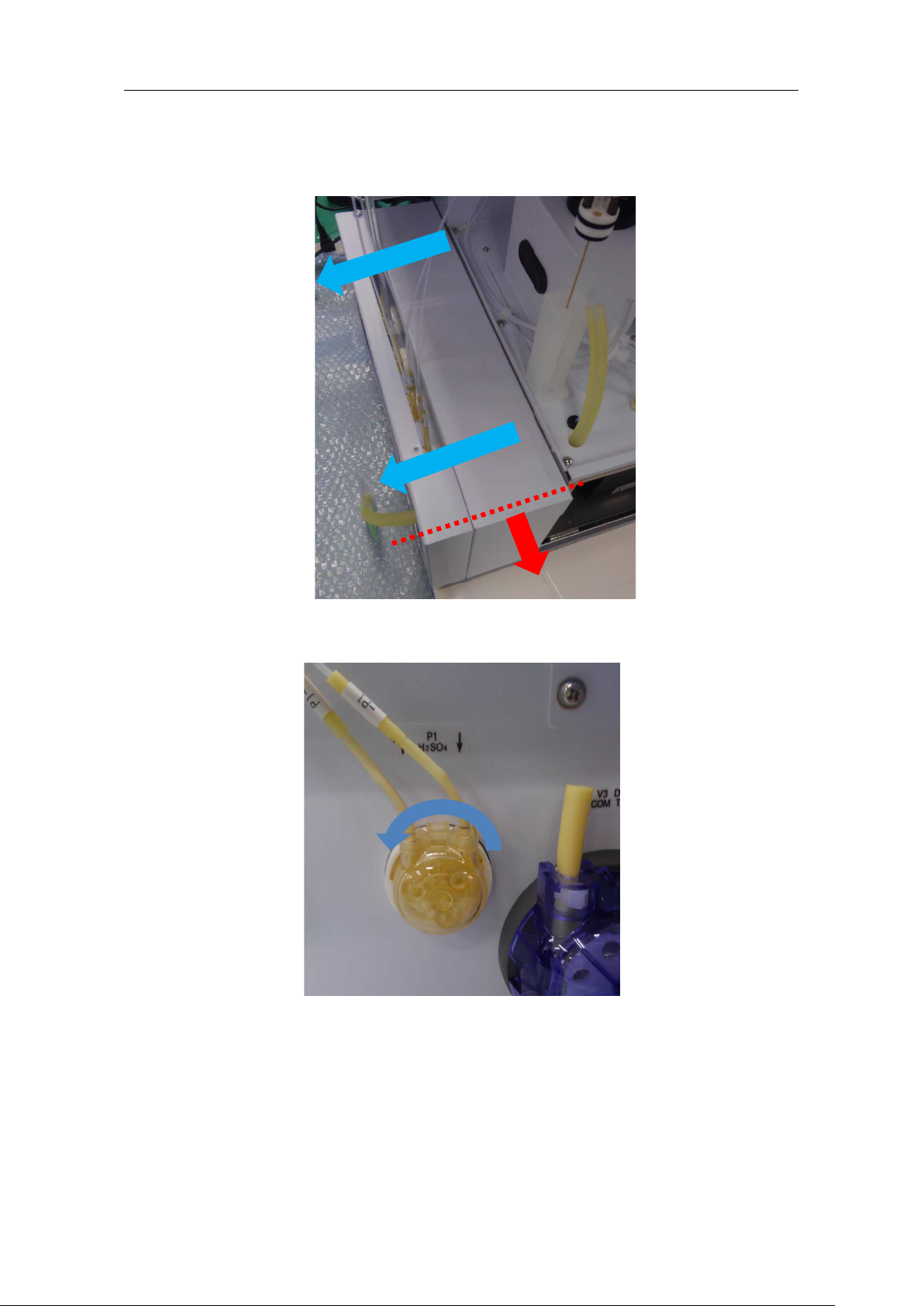
Slide the pump mounting base toward you, and then move it to the left and detach the
base.
Turn the head of the reagent pump to be replaced counterclockwise, and detach the head.

11
From the inside of the pump mounting base, remove the nuts holding the pump, and
disconnect its connector. Then replace the pump.
After installing a new reagent pump, reassemble the parts using the reverse procedure.
Replacing the measuring cap and bubbler
OntheMaintenancescreenofthemeasuringsoftware,movethe measuringcapposition,
and then turn off the power of the analyzer. * SetARM to [2: B STAGE], and then set LIFT
to [6: MEASURE].

Unscrew the three screws holding the cap, and then remove the cap.
Detach the reagent tube, reaction tube, and bubbler from the removed cap.
Assemble the cap.
* Pass the bubbler through the cap rubber in advance.
* Do not tighten the screws too much. If the rubber is crushed, the insertion of a tube will
become difficult.
* Adjust the protrusion of the bubbler to 114 mm from the top of the cap gasket.
114 mm

13
Reassemble the parts using the reverse procedure. Slide the spring over each resin
screw, and tighten the screws with a screwdriver until the screws do not turn anymore.
* If you tighten the screws too much, you may damage them.
* If the bubbler is leaning, you can correct it by loosening the screws.
Confirm that the protrusion of the bubbler is 114 mm from the top of the cap gasket.
* Excessively tightening the countersunk head screw of thecapmakes itdifficult to adjust
the protrusion of the bubbler.
114 mm

Replacing the reaction tube
Referring to [3.3. Replacing the measuring cap and bubbler], unscrew the three screws
holding the cap, and then remove the cap.
Pull the old reaction tubes out of the cap.
Connect the yellow-marked tube to the bubbler.
In addition, insert the transparent tube into the cap hole closer to you.
Referring to [3.3. Replacing the measuring cap and bubbler - Step ], fix the cap in
place using the reverse procedure.

15
Run the tube along the route as shown in the picture below.
Hook the tube onto the clamps circled in the picture below.
Connect the yellow-marked tube to the connector on the right side, and connect the
green-marked tube to the connector on the left side.
Insert the tube, and turn the connector clockwise to fix the tube in place.
* Lightly pull the tubes to confirm that the tubes do not come off.

Pass the transparent tube through the black rubber grommet, and insert the tube into the
I-shaped joint below.
* Push the tube down until the tip of the tube is slightly visible. If the insertion is difficult,
insert the tube after detaching the dehumidifier tube.
Replacing the reagent tube
Referring to [3.3. Replacing the measuring cap and bubbler], remove the cap.
* Before starting this work, discharge any reagent from the tube by executing [Reagent
Discharge].
Pull the old reagent tubes (P1 and P2) out of the cap.
Connect new reagenttubes (P1 and P2) to themeasuring cap. Make sure that the length
is 15 mm from the top of the cap gasket.
Table of contents
Other Nic Measuring Instrument manuals


Popular Measuring Instrument manuals by other brands


Endress+Hauser
Endress+Hauser Cubemass DCI technical information

Extech Instruments
Extech Instruments 475055 user guide

Secure
Secure Sprint 211 installation manual

International Light Technologies
International Light Technologies ILT710 Operation manual

P3 International
P3 International Kill A Watt P4400 Operation manual

SKF
SKF Microlog GX Series user manual

Gutermann
Gutermann AQUASCAN 610 operating manual

Keithley
Keithley TEC SourceMeter 2510 user manual

Haglof
Haglof Vertex Laser II VL402 Operator's manual

Endress+Hauser
Endress+Hauser FHG65 technical information

Anritsu
Anritsu MD1230A Service manual

Eggtimer Rocketry
Eggtimer Rocketry Eggtimer Classic Assembly manual