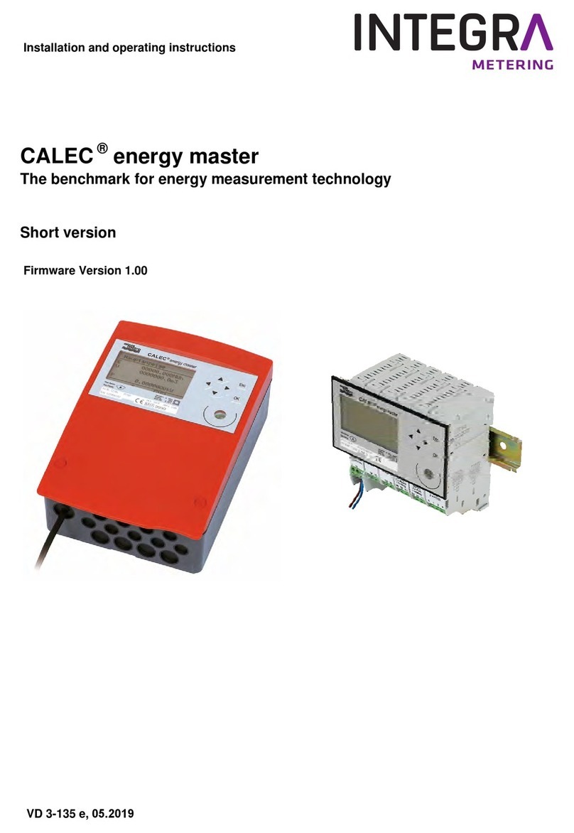
INTEGRA Merering AMFLO MAG Basic Service manual

VD 6-855 def 04.2017
Montage- und Bedienungsanleitung Seite 2 - 8
Mounting and operating instructions Page 9 - 15
Instructions de montage et mode d’emploi Page 16 - 24
AMFLO
®
MAG Basic
Inhaltsverzeichnis
Allgemeine Informationen 2
Technische Daten 3
Montagehinweise 5
Elektrische Installation 6
Garantie 7
Fehlerbehebung 8
Table of contents
General informations 9
Technical data 10
Mounting instructions 12
Electrical installation 13
Warranty 14
Trouble shooting 15
Sommaire
Informations générales 16
Spécifications techniques 17
Instructions de montage 19
Installation électrique 20
Garantie 21
Dépannage 22

2AMFLO
®
MAG Basic
Allgemeine Informationen
Sicherheitsanweisungen
Bestimmungsgemässe Verwendung
Der AMFLO
®
MAG Basic ist als Durchflussgeber für leitfähige Flüssigkeiten konzipiert. Dieses Gerät ist für die Erfassung, Berechnung und
Versendung von Informationen zu Volumenströmen innerhalb der angegebenen Spezifikationen ausgelegt. Eine unsachgemässe oder nicht
bestimmungsgemässe Verwendung kann dazu führen, dass die Betriebssicherheit des Geräts nicht mehr gewährleistet ist. Der Hersteller
übernimmt für daraus resultierende Schäden keine Haftung.
Installation, Inbetriebnahme und Betrieb
Die Installation, der Anschluss an die Stromversorgung, die Inbetriebnahme und die Wartung des Geräts müssen durch geschultes, quali-
fiziertes Fachpersonal erfolgen, das zur Ausführung solcher Arbeiten unter Berücksichtigung der geltenden Richtlinien und Gesetzen dazu
berechtigt ist. Das jeweilige Fachpersonal muss diese Betriebsanleitung gelesen und verstanden haben sowie die enthaltenen Anweisungen
befolgen.
Legen Sie vor der Installation die betreffende Anlage still und unterbrechen Sie die Stromversorgung sowie stellen Sie sicher, dass niemand
diese ohne Ihre Zustimmung wieder in Betrieb setzen kann.
Beachten Sie folgende Punkte:
• Umgebungsbedingungen und Einbauposition
• Einhaltung der Betriebsdaten (Spannungen, Temperaturen, usw.)
• Schutz vor Überspannung (Geeignete Sicherung, kein Elektroschweissen an verbunden Anlagen, usw.)
Betriebssicherheit
Der Hersteller behält sich das Recht vor, ohne Vorankündigung Änderungen an den technischen Daten vorzunehmen. Bei Ihrem Händler
vor Ort erhalten Sie aktuelle Informationen und neue Versionen dieser Betriebsanleitung.
Geräteeinsendung
Legen Sie dem Gerät immer ein vollständig ausgefülltes „Reparaturformular“ bei. Nur dann kann Aquametro ein eingesendetes Gerät
transportieren, kalibrieren, untersuchen oder reparieren.
Hinweise zu Sicherheitsbestimmungen und -symbolen
Die Geräte sind so konzipiert, dass sie die neuesten Sicherheitsanforderungen erfüllen. Sie wurden getestet und in einem Zustand ausge-
liefert, der einen sicheren Betrieb gewährleistet. Bei unsachgemässer oder nicht bestimmungsgemässer Verwendung können die Geräte
jedoch eine Gefahrenquelle darstellen. Achten Sie daher immer besonders auf die in dieser Anleitung durch folgende Symbole dargestellten
Sicherheitshinweise:
Achtung!
„Achtung“ weist auf eine Handlung oder Massnahme hin, die bei falscher Ausübung zu Verletzungen oder einem
Sicherheitsrisiko führen kann. Befolgen Sie stets die Anweisungen und gehen Sie mit Vorsicht vor.
Vorsicht!
„Vorsicht“ weist auf eine Handlung oder Massnahme hin, die bei falscher Ausübung zu einer fehlerhaften
Funktionsweise oder zur Zerstörung des Geräts führen kann. Befolgen Sie stets die Anweisungen.
Hinweis!
„Hinweis“ weist auf eine Handlung oder Massnahme hin, die sich bei falscher Ausübung indirekt auf den Betrieb
auswirken oder eine unerwartete Reaktion des Geräts auslösen kann.
Zulassung, Konformitätsbewertung und Eichung
Das Gerät ist nach der europäischen Richtlinie 2004/22/EG (MID-Richtlinie) sowie nach PTB TR K7.2 (Kälte) für den Einsatz im geschäftlichen
Verkehr zugelassen. In den meisten Ländern unterliegen Energiemessgeräte für den geschäftlichen Verkehr der Eichpflicht und müssen nach
Ablauf der Eichperiode nachgeeicht werden. Für die Einhaltung der eichrelevanten Bestimmungen ist der Betreiber verantwortlich.

Technische Daten
* Bitte überprüfen Sie die chemische Beständigkeit des Geräts (Messrohr, Elektroden und Dichtungen) für das eingesetzte Medium!
Messbereich (Zugelassen nach EN 1434 Klasse 2, Messdynamik 1:100)
* entspricht Standardwerten von qp nach EN 1434
Abmessungen und Geräteanschluss
3AMFLO
®
MAG Basic
Nennweiten DN 125 - 250
Elektroden 2 Signalelektroden und 1 Erdungselektrode, Edelstahl 1.4571
Flüssigkeit Wasser und andere Flüssigkeiten*
Nenndruck PN 16
Liner Hartgummi
Flansch und Mantelrohr Stahl lackiert (Flansch nach EN 1092-1)
Schutzklasse IP 67
Temperaturspanne Flüssigkeit TFluid = 0 - 80 °C
Umgebungstemperatur TAmb = 5 - 55 °C
Min. eletrische Leitfähigkeit 40 μS/cm
Genauigkeit ±0.5 % (±0.004 m/s unterhalb 0.5 m/s)
Ausgang max. 200 Hz (Pulsdauer 2.5 ms bei 200 Hz), SSR (Solid State Relais) passiv, max. 48 V / 50 mA
Messbereich 0.04 - 10 m/s (entspricht ca. 1/2 qi - qs)
Anschluss Klemmleiste im geschützten Anschlussraum
Spannungsversorgung 24 VDC +/- 10%, 150 mA (z. B. über Rechenwerk CALEC
®
)
Nennweite DN mm 125 150 200 250
Zoll 5 6 8 10
qi (Minimaldurchfluss) m
3
/h 4 6 10 16
qp (Nenndurchfluss) m
3
/h 400 600 1000 1600
qs (Maximaldurchfluss) m
3
/h 440 660 1100 1800
Typischer Arbeitsbereich (~1 bis m
3
/h 50 - 65 - 120 - 200 -
5 m/s) 220 300 570 900
Impulswert L/Puls 1 2 2 5
Nennweite DN mm 125 150 200 250
Zoll 5 6 8 10
L mm 250 300 350 450
Di mm 126 155 203 256
Da mm 250 285 340 405
H mm 194 209 243 270
Gewicht kg 20 27 41 62
Da
Di
H
L

4AMFLO
®
MAG Basic
Messfehlergrenze
Genauigkeit
Die Messgenauigkeit des Gerätes beträgt:
±0.5 % (±0.004 m/s unterhalb von 0.5 m/s)
unter den folgenden Referenzbedingungen:
Flüssigkeitstemperatur: 20 °C
Statischer Flüssigkeitsdruck: >3 bar
Umgebungstemperatur: 23 °C
Vorwärmzeit des Gerätes: 15 min.
Flüssigkeit: Wasser
-5
-4
-3
-2
-1
0
1
2
3
4
5
V (m/s)
%
Nach EN 1434
AMFLO®MAG Basic
Typische Fehlerkurve

5AMFLO
®
MAG Basic
Montagehinweise
Der Durchflussmesser ist bevorzugt horizontal unter Beachtung der Durchflussrichtung (Pfeil auf Gehäuse) einzubauen (vertikaler Einbau
möglich). Die Messelektroden müssen bei horizontalem Einbau waagrecht ausgerichtet werden (Anschlussbox nach oben). Dichtungen,
Schrauben sowie Anzugsdrehmomente gemäss Rohrleitungssystem verwenden. Um den Liner des Geräts nicht zu beschädigen darf ein
Anzugsdrehmoment von 150 Nm nicht überschritten werden. Weitere Empfehlungen und Montagebedingungen siehe nachfolgende Tabelle.
Horizontaler und vertikaler Einbau möglich
Zu vermeiden Empfehlung
Beachten Sie die Informationen auf dem Typenschild!
Das Gerät muss spannungsfrei montiert werden (keine Torsions- oder Biegespannung). Gegebenenfalls sind Abstützun-
gen für die Leitung und das Gerät zu verwenden.
Das Gerät ist durch werkseitig angebrachte Siegel vor Manipulation und unbefugter Wartung geschützt. Durch unsach-
gemässe Verwendung und Montage des Gerätes werden die Siegel zerstört, was zum Erlöschen der Garantie führt.
Die Montage des Durchfluss-
messers in langen Leitungen
ohne Abstützungen ist zu ver-
meiden.
Teilweise gefüllte Leitungen
führen zu erheblichen Messfeh-
lern und sind daher zu vermei-
den.
Vermeiden Sie Falschmessun-
gen durch Einbau in der Nähe
von Ventilen, Krümmern, Pum-
pen, usw..
Grosse Anfangszwischenräume
zwischen Leitung und Durch-
flussmesser können beim An-
ziehen der Muttern zu hohen
Torsionsspannungen und Biege-
dehnungen am Gerät führen.
Luftblasen können bei Elektro-
denkontakt die Messung stören.
In Anlagen mit an das Gerät
anschliessenden langen Lei-
tungen sollten schwingungs-
hemmende Anschlussstücke
verwendet werden.
Während des Betriebs muss die
Leitung jederzeit voll sein.
Für genaue Messungen mindes-
tens Einlaufstrecke von 3 × DN
und Auslaufstrecke von 2 × DN
einhalten.
Die Zwischenräume für die
Dichtungen müssen so klein
wie möglich sein, so dass das
Gerät beim Anziehen der Mut-
tern nicht beansprucht wird.
Montagewinkel bei Sensorhals
nach oben +/- 45°.
-45 +45
2 x
3 x

6AMFLO
®
MAG Basic
Elektrische Installation
Stromversorgung
24 VDC ±10 % (max. Strom 150 mA).
Die Spannungsabweichungen von ±10 % dürfen nicht überschritten werden.
Verdrahtung
Anschlusskabel mit Querschnitt 0.25…1.5 mm2verwenden. Enden 8 mm abisolieren ggf. Aderendhülsen verwenden.
Maximale Kabellänge 10 m aufgrund EMV-Richtlinie
Impulsausgang (2/3):
Modus: passiv (solid state relais)
Max. Strom/max. Spannung: 50 mA / 48 V
Max. Ausgangsfrequenz: 200 Hz
Nennweite DN mm 125 150 200 250
Zoll 5 6 8 10
Impulswert L 1 2 2 5
Durchfluss
Status
Common
Impuls
+24V DC
GND
LED:
Status
Impuls
1
2
3
4
5
1
2
3
4
5

7AMFLO
®
MAG Basic
Potenzialausgleich
Die Messgenauigkeit des Gerätes wird durch den richtigen Potenzialausgleich sichergestellt. Das Gerät wird durch ein Kabel mit geringem
Widerstand mit einem Anschlussstück an der seitlichen Schraube am Flansch geerdet.
Metallrohr ohne Innenbeschichtung
- Potentialausgleich zum Rohrsystem und Erdung notwendig
Anschluss für
Potentialausgleich
Für Kunststoff- oder beschichtete Leitungen Erdungsringe verwenden.
Garantie
Die Garantie erlischt in folgenden Fällen:
- Ein werkseitig angebrachtes Siegel ist zerstört.
- Das Gerät wird für andere Zwecke verwendet als die, die in der Dokumentation angegeben sind (Anwendung, Flüssigkeit, Betriebs-
temperatur, Druck, Durchflussgeschwindigkeit, etc.).

8AMFLO
®
MAG Basic
Betrieb und Fehlerbehebung
Für die ordnungsgemässe Funktion muss das Gerät korrekt an eine Spannungsversorgung angeschlossen und das Messrohr komplett
gefüllt sein.
Im Anschlussraum auf der Anschlussplatine befinden sich zwei LEDs zur Betriebs- und/oder Fehleranzeige mit den folgenden drei Mög-
lichkeiten:
- Weisse LED blinkt bzw. leuchtet: Durchflussindikation analog der Ausgangsimpulse
- Rote LED blinkt bzw. leuchtet: negativer Durchfluss bzw. entgegen Durchflussrichtung (Pfeilrichtung auf Gehäuse)
- Weisse und rote LED blinken bzw. leuchten gleichzeitig: Durchfluss oberhalb der Spezifikation
Problem Mögliche Ursachen
Keine Ausgangsimpulse Ist das Gerät an die Stromversorgung angeschlossen worden?
Entspricht die Spannung den Spezifikationen?
Ist die Leitung teilgefüllt oder leer?
Liegt die Strömungsgeschwindigkeit oder Durchflussmenge ausserhalb
der Spezifikation?
Falsche Durchflussrichtung?
Sind die Elektroden verschmutzt?
Falsche Verdrahtung?
Instabile Messungen Ist die Durchflussmenge stabil?
Liegt die Strömungsgeschwindigkeit oder Durchflussmenge ausserhalb
der Spezifikation?
Ist der Potentialausgleich ordnungsgemäss durchgeführt?
Sind die Elektroden verschmutzt?
Ist die Leitung teilgefüllt oder leer?
Sind Gasblasen im Medium?

9AMFLO
®
MAG Basic
General Information
Safety instructions
Designed use
The AMFLO
®
MAG Basic is designed as a flow meter for conductive liquids. This unit is designed for acquisition, calculation and sending
information of volumetric flows within the mentioned specifications. Resulting from incorrect use or from use other than that designated,
can suspend the operational safety of the devices. The manufacturer accepts no liability for damages being produced from this.
Installation, commissioning and operation
Installation, connection to the electric supply, commissioning and maintenance of the device must be carried out by trained, qualified speci-
alists authorized to perform such works under consideration of regulations and current laws. The specialist must have read and understood
these Operating Instructions and must follow the instructions they contain.
Before working make sure to shut down the relevant system and disconnect the power supply. Furthermore ensure that nobody can activate
the relevant system or reconnect power supply without your permission.
Pay especially attention to the following points:
• Environment conditions and mounting position
• Compliance with operation data (voltage, temperature, etc.)
• Protections like for Overvoltage (suitable fuse, no electrical welding at connected systems, etc.)
Operational safety
The manufacturer reserves the right to modify technical data without prior notice. Your local distributor will supply you with current infor-
mation and updates to these Operating Instructions.
Return of the instruments
Always enclose a fully completed “Repair Form” with the device. Only then Aquametro can transport, verificate, check or repair a returned
device.
Notes on safety conventions and icons
The devices are designed to meet state-of-the-art safety requirements. They have been tested and left the factory in a condition in which they
are safe to operate. They can, however, be a source of danger if used incorrectly or for use other than the designated use. Consequently,
always pay particular attention to the safety instructions indicated in these Operating Instructions by the following symbols:
Warning!
“Warning” indicates an action or procedure which, if not performed correctly, can result in injury or a safety hazard.
Comply strictly with the instructions and proceed with care.
Caution!
“Caution” indicates an action or procedure which, if not performed correctly, can result in incorrect operation or
destruction of the device. Comply strictly with the instructions.
Note!
“Note” indicates an action or procedure which, if not performed correctly, can have an indirect effect on operation
or trigger an unexpected response on the part of the device.
Approval, declaration of conformity and verification
This device is approved according to the MID directive 2004/22/CE and the special cooling approval according to the PTB TR K7.2. Inst-
ruments for commercial heating and cooling measurements are subject to commercial verification in most countries. Equipment subject
to this obligation must be recalibrated resp. reverificated after expiry of the calibration period. The operator is responsible for compliance
with the regulations.

10 AMFLO
®
MAG Basic
Technical data
* Please check the chemical resistance of the device (liner, electrodes and gaskets) for the used medium!
Range of measurement (approved according to EN 1434 class 2, measurement dynamic 1:100)
* equivalent to standard values of qp according to EN 1434
Device dimensions and connections
Nominal sizes DN 125 - 250
Electrodes 2 signal electrodes and 1 ground electrode, stainless steel 1.4571
Fluid Water and other fluids*
Nominal pressure PN 16
Liner Hard rubber
Flange and outer casing Steel painted (Flange according to EN 1092-1)
Protection class IP 67
Fluid temperature range TFluid = 0 - 80 °C
Ambient temperature TAmb = 5 - 55 °C
Min. electrical conductivity 40 mS/cm
Accuracy ±0.5 % (±0.004 m/s slower than 0.5 m/s)
Digital output max. 200 Hz (pulse duration 2.5 ms at 200 Hz), SSR (Solid State Relais) passive, max. 48 V / 50 mA
Range of measurement 0.04 - 10 m/s (equivalent about 1/2 qi - qs)
Connections Terminals inside protected junction box
Power supply 24 VDC +/- 10%, 150 mA (e. g. by calculator CALEC
®
)
Nominal diameter DN mm 125 150 200 250
inch 5 6 8 10
qi (minimal flow) m
3
/h 4 6 10 16
qp (nominal flow) m
3
/h 400 600 1000 1600
qs (maximal flow) m
3
/h 440 660 1100 1800
Typical operating range (~1 to m
3
/h 50 - 65 - 120 - 200 -
5 m/s) 220 300 570 900
Pulse value l/pulse 1 2 2 5
Da
Di
H
L
Nominal diameter DN mm 125 150 200 250
inch 5 6 8 10
L mm 250 300 350 450
Di mm 126 155 203 256
Da mm 250 285 340 405
H mm 194 209 243 270
Weight kg 20 27 41 62

11AMFLO
®
MAG Basic
Measuring error limits
Accuracy
The measurement accuracy of the device is:
±0.5 % (±0.004 m/s slower than 0.5 m/s)
under the following reference conditions:
Fluid temperature: 20 °C
Static fluid pressure: >3 bar
Ambient temperature 23 °C
Device warm-up time 15 min.
Fluid: Water
-5
-4
-3
-2
-1
0
1
2
3
4
5
V (m/s)
%
According to EN 1434
AMFLO®MAG Basic
Typical error curve

12 AMFLO
®
MAG Basic
Mounting instructions
As the type plate indicates, the normal mounting position of the device considering the flow direction (arrow on housing) is horizontal (also
vertical possible) with the electrodes lying in a horizontal plane. For horizontal mounting the electrodes axis must lie in a horizontal plane
(connection box upwards). Seals, screws and tightening torques in accordance with the pipe work. To prevent damage to the device’s liner,
the tightening torque must not exceed 150 Nm. Conditions of mounting are given in the table below.
Horizontal and vertical mounting possible
Avoid Recconmended
Consult the information given on the type plate.
The device must be free of tension when mounted (no torsional or bending strains). If necessary pipework and device
mounting supports should be used to ensure this.
The device is protected against manipulation and unauthorized maintenance by factory seals. The seals will be broken
by incorrect handling and mounting of the device, leading to immediate forfeiture of the warranty.
Avoid installing the flow sensor
in long pipes without supports.
Avoid vibrations.
Partially filled pipes will cause
considerable measuring errors
and must be avoided.
Avoid faulty readings resulting
from installation close to valves,
elbows, pumps etc..
Large initial gaps between pipe
work and flow sensor can result
in large torsional and bending
strains on the device when tigh-
tening the nuts.
Air bubbles can contact electro-
des and disturbe measuring.
In installations with long pipes
connecting to the device, an-
tivibration joints should be used.
In operation, the pipe must be
completely full at all times.
To get precise readings, keep to
inlet pipe section of 3 × ND and
outlet section of 2 × ND.
The gaps provided for the gas-
kets must be as small as pos-
sible so that, when tightening
the nuts, the device is not under
strain.
Mounting angle with sensor
neck upwards +/- 45°.
-45 +45
2 x
3 x

13AMFLO
®
MAG Basic
Electrical installation
Power supply
24 VDC ±10 % (max. current 150 mA).
The voltage deviations of ±10% must not be exceeded.
Wiring
Use a connecting cable with a cross section of 0.25 – 1.5 mm2. Strip 8 mm of the outer insulation at the ends or use end ferrules if
necessary.
Maximum cable length 10 m according to the EMC Directive.
Pulse output (2/3):
Mode: passive (solid state relais)
Max. current/max. voltage: 50 mA, 48 V
Max. output frequency: 200 Hz
Nominal diameter DN mm 125 150 200 250
inches 5 6 8 10
Pulse value L 1 2 2 5
Flow
Status
Common
Pulse
+24V DC
GND
LED:
Status
Pulse
1
2
3
4
5
1
2
3
4
5

14 AMFLO
®
MAG Basic
Potential equalisation
The measuring accuracy of the device is assured by proper potential equalization. The device is grounded to a suitable grounding point by
means of a low resistance cable with a lug connected to the lateral screw on the flange.
Metal pipe without internal coating
- Instal equipotential bonding to pipework and ground
Potential equalisation
connection
For plastic or internal coated pipes use grounding rings.
Warranty
The warranty ceases in the following cases:
- A factory seal is broken.
- The device is used for purposes other than those specified in the documentation (application, fluid, operating temperature, pressure,
flow velocity, etc.).

15AMFLO
®
MAG Basic
Operation and trouble shooting
For the device to function correctly it must be connected to a power supply and the measurement pipe must be completely full.
In the junction box are two LEDs which indicating the operating status and/or faults by means of three patterns:
- White LED flashes or is illuminated: flow indication analogous to the output pulse
- Red LED flashes or is illuminated: flow negative or against flow direction (arrow direction on housing)
- White and red LED flash or are illuminated simultaneously: flow above specified level
Problem Possible causes
No output volume pulses Has the device been connected to the power supply?
Does the voltage correspond to the specifications?
Is the pipework partially filled or empty?
Is there flow?
Is the flow velocity or the flow rate outside the specification?
Is the flow rate below the cutoff value?
Has the device been mounted in the right direction?
Are the electrodes dirty?
Is the electrical wiring correct?
Unstable measurements Is the actual flow rate stable?
Is the flow velocity or flow rate outside the specification?
Is the device properly grounded?
Are the electrodes dirty?
Is the pipework only partially full?
Are gas bubbles in the pipework?

16 AMFLO
®
MAG Basic
Informations générales
Consignes de sécurité
Utilisation conforme
L‘AMFLO
®
MAG Basic est un débitmètre pour liquides conducteurs. Cet appareil est conçu pour la saisie, le calcul et l‘envoi de données
sur les flux de volumes au sein des spécifications indiquées. En cas d‘utilisation incorrecte ou non conforme, la sûreté opérationnelle de
l‘appareil n‘est plus garantie. Le fabricant décline toute responsabilité pour les dommages découlant d‘une telle utilisation.
Installation, mise en service et fonctionnement
L‘installation, le branchement électrique, la mise en service et la maintenance de l‘appareil doivent être assurés par des techniciens
spécialisés formés, qualifiés et autorisés à effectuer ces travaux dans le respect des directives et lois en vigueur. Les techniciens doivent
avoir lu et compris le présent manuel d‘utilisation et en respecter les consignes.
Avant de procéder à l‘installation, arrêtez le système, coupez l‘alimentation électrique et assurez-vous que personne ne peut la rétablir
sans votre permission.
Faites particulièrement attention aux points suivants :
• Conditions environnantes et position de montage
• Respect des données opérationnelles (tensions, températures, etc.)
• Protection contre la surtension (fusible adapté, pas de soudage électrique sur les installations raccordées, etc.)
Sûreté opérationnelle
Le fabricant se réserve le droit de modifier les caractéristiques techniques sans préavis. Votre distributeur local vous fournira les informa-
tions actuelles et les mises à jour du présent manuel d‘utilisation.
Retour des instruments
Joignez toujours à l‘appareil un «formulaire de réparation» complet. Ceci est indispensable pour qu‘Aquametro puisse transporter,
étalon-ner, examiner ou réparer l‘appareil retourné.
Remarque sur les dispositions et symboles de sécurité
Les appareils sont conçus pour répondre aux toutes dernières exigences de sécurité. Ils ont été testés et ont quitté l‘usine dans un état
permettant une utilisation sûre. Cependant, ils peuvent s‘avérer dangereux s‘ils sont utilisés de façon incorrecte ou non conforme. Par
conséquent, faites tout particulièrement attention aux consignes de sécurité du présent manuel signalées par les symboles suivants:
Danger!
«Danger» indique une action ou une procédure qui, si elle n‘est pas effectuée correctement, peut causer
des blessures ou remettre en cause la sécurité. Respectez les instructions à la lettre et soyez prudent.
Prudence!
«Prudence» indique une action ou une procédure qui, si elle n‘est pas effectuée correctement,
peut causer un dysfonctionnement ou une panne de l‘appareil. Respectez les instructions à la lettre.
Attention!
«Attention» indique une action ou une procédure qui, si elle n‘est pas effectuée correctement,
peut avoir un effet indirect sur le fonctionnement ou déclencher une réaction inattendue de la part de l‘appareil.
Homologation, Conformité CE et étalonnage
L’appareil est homologué selon les directives CE 2004/22/CE (directive MID) et PTB TR K7.2 (Frigories) et peut de ce fait être utilisé à des
fins de transactions commerciales. Dans la plupart des pays, les compteurs d’énergie thermique utilisés pour des transactions commerci-
ales sont soumis à une obligation d’étalonnage et doivent être réétalonnés à l’issue de la période de validité de l’étalonnage. L’exploitant
est seul responsable du respect de cette obligation.

17AMFLO
®
MAG Basic
Spécifications techniques
* Veuillez vous assurer de la résistance chimique des matériaux du débitmètre (tube de mesure, électrodes) en contact avec votre fluide.
Plage de mesure (homologation selon EN 1434 classe 2, plage dynamique 1:100)
* pour des valeurs standards de qp homologuées selon EN 1434
Dimensions et connexions de l’appareil
Diamètres nominaux DN 125 - 250
Électrodes 2 électrodes pour signal de mesure et 1 électrode de terre, acier inoxydable 1,4571
Fluide Eau et autres fluides*
Pression nominale PN 16
Revêtement Caoutchouc dur
Bride et tube extérieur Acier laqué (bride selon EN 1092-1)
Classe de protection IP 67
Plage de temp. de fluide TFluid = 0 - 80 °C
Température ambiante TAmb = 5 - 55 °C
Conductivité électr. mini. 40 μS/cm
Précision ±0.5 % (±0,004 m/s en dessous de 0,5 m/s)
Sortie maxi. 200 Hz (durée d’impulsion 2,5 ms à 200 Hz), SSR (Solid State Relais) passive, maxi. 48 V / 50 mA
Plage de mesure 0,04 - 10 m/s (correspond à env. 1/2 qi - qs)
Raccordement Bornier dans boîte de jonction
Alimentation 24 volts CC +/- 10%, 150 mA (p. ex. via calculateur CALEC
®
)
Diamètre nominal DN mm 125 150 200 250
Pouce 5 6 8 10
qi (débit minimal) m
3
/h 4 6 10 16
qp (débit nominal) m
3
/h 400 600 1000 1600
qs (débit maximal) m
3
/h 440 660 1100 1800
Plage de travail type (~1 à m
3
/h 50 - 65 - 120 - 200 -
5 m/s) 220 300 570 900
Valeur d’impulsion L/impulsion 1 2 2 5
Diamètre nominal DN mm 125 150 200 250
Pouces 5 6 8 10
L mm 250 300 350 450
Di mm 126 155 203 256
Da mm 250 285 340 405
H mm 194 209 243 270
Poids kg 20 27 41 62
Da
Di
H
L

18 AMFLO
®
MAG Basic
Tolérance de mesure
Précision
La précision de mesure de l’appareil est de :
±0.5 % (±0.004 m/s en-dessous 0.5 m/s)
dans les conditions de référence suivantes :
Température de fluide : 20 °C
Pression de fluide statique : >3 bar
Température ambiante: 23 °C
Temps de préchauffage de l’appareil: 15 min.
Fluide: Eau
-5
-4
-3
-2
-1
0
1
2
3
4
5
V (m/s)
%
Selon EN 1434
AMFLO®MAG Basic
Courbe d’erreur typique

19AMFLO
®
MAG Basic
Instructions de montage
Comme l’indique la plaquette signalétique, la position de montage normale de l’appareil (flèche sur le boîtier) est à l’horizontale (position
verticale également possible), avec les électrodes disposées sur un plan horizontal (boîte de jonction vers le haut). Utiliser les joints, vis et
couples de serrage conformément au système de conduites. Pour ne pas endommager le revêtement de l’appareil, il convient de ne pas
dépasser un couple de serrage de 150 Nm. De plus amples informations sur les conditions de montage sont présentées dans le tableau
ci-dessous.
Possibilité de montage horizontal et vertical
A éviter Recommandé
Consultez les informations mentionnées sur la plaquette signalétique.
L’appareil monté ne peut être soumis à des tensions (pas de contraintes de torsion ni de flexion). Utiliser si nécessaire
des supports de montage pour la tuyauterie et l’appareil.
L’appareil est protégé contre toute erreur de manipulation au moyen de sceaux d’usine. En cas de manipulation et de
travaux de maintenance non autorisés, les sceaux se brisent, entraînant l’invalidation immédiate de la garantie.
Eviter d’installer le débitmètre
sur de longs tuyaux sans sup-
ports.
Les tuyaux partiellement remplis
peuvent provoquer des erreurs
de mesure considérables et doi-
vent être évités.
Pour éviter les risques d’erreurs,
ne pas monter à proximité de
vannes, coudes, pompes, etc..
Un interstice important entre la
tuy. et le débitm. peut entraîner
d’importantes contraintes de
torsion et de flexion sur l’app.
lors du serrage des écrous.
Les bulles d’air peuvent, en
contact avec les électrodes,
influencer la mesure.
Dans des installations avec de
longs tuyaux raccordés à l’ap-
pareil, il convient d’utiliser des
joints antivibration.
En mode opérationnel, le tuyauy
doit en permanence être com-
plètement rempli.
Pour des mesures précises,
prévoir une section d’entrée de
minimum 3 × DN et une section
de sortie de 2 × DN.
Les interstices prévus pour les
joints doivent être aussi faibles
que possible de façon à ce que
l’app. ne soit soumis à aucune
contrainte lors du serrage des
écrous.
Angle de montage avec capteur
vers le haut +/- 45°.
-45 +45
2 x
3 x

20 AMFLO
®
MAG Basic
Installation électrique
Alimentation
24 VDC ±10 % (courant 150 mA max.).
Les variations de tension spécifiées de ±10 % ne doivent pas être dépassées.
Câblage
Utiliser un câble de raccordement présentant une section transversale comprise entre 0,25 et 1,5 mm2. Dénuder les extrémités sur 8 mm,
utiliser des douilles d’extrémité de câble si nécessaire.
Longueur maximale de câble 10 m selon les directives EMC.
Sortie d’impulsions (2/3):
Mode: passif (solid state relais)
Courant max./tension max. : 50 mA, 48 V
Frequence de sortie max.: 200 Hz
Débit
Statut
Common
Impulsion
+24V DC
GND
DEL:
Statut
Impulsion
1
2
3
4
5
1
2
3
4
5
Diamètre nominal DN mm 125 150 200 250
pouces 5 6 8 10
Valeur d’impulsion L 1 2 2 5
Table of contents
Languages:
Other INTEGRA Merering Measuring Instrument manuals
Popular Measuring Instrument manuals by other brands
Garmin
Garmin GRA 5500 installation manual

Medical International Research
Medical International Research spirodoc user manual
Precision Digital Corporation
Precision Digital Corporation PROVU PD6402 instruction manual
Hach
Hach 2100P Instrument and procedure manual

Newport Electronics
Newport Electronics IDP INFINITY D Operator's manual
Bowles
Bowles UW-7 user manual
Micromeritics
Micromeritics ASAP 2420 1-mmHg Transducer Option Installation instruction

SafeGuard
SafeGuard MegaGuard WalkPlus instruction manual
Extech Instruments
Extech Instruments 461895 user guide

Mitutoyo
Mitutoyo HTD-R user manual
Tecfluid
Tecfluid AD Series instruction manual
Newall
Newall NMS 100 user manual
