Fisher Scientific Isotemp OV700G User manual

LT2042X1 • 3/30/09 Serial Number________________________
Isotemp®Premium Ovens
700 Series
Operation Manual
and Parts List
Gravity Ovens Forced Air Ovens
OV700 (Small) OV700F (Small)
13-247-725 & -726 13-247-725F & -726F
OV701 (Medium) OV701F (Medium)
13-247-737 & -738 13-247-737F & -738F
OV702 (Large) OV702F (Large)
13-247-750 & -751 13-247-750F & -751F

Introduction ........................................................................................................................................................ 3
Specifications ......................................................................................................................................................5
Performance Characteristics ........................................................................................................................5
Electrical Requirements................................................................................................................................6
Power Requirements ....................................................................................................................................6
Chamber Volumes ........................................................................................................................................6
Chamber Dimensions ..................................................................................................................................6
Installation ..........................................................................................................................................................7
Selecting a Location ....................................................................................................................................7
Unpacking ....................................................................................................................................................7
Preparing the Oven ......................................................................................................................................8
Power Switch ................................................................................................................................................8
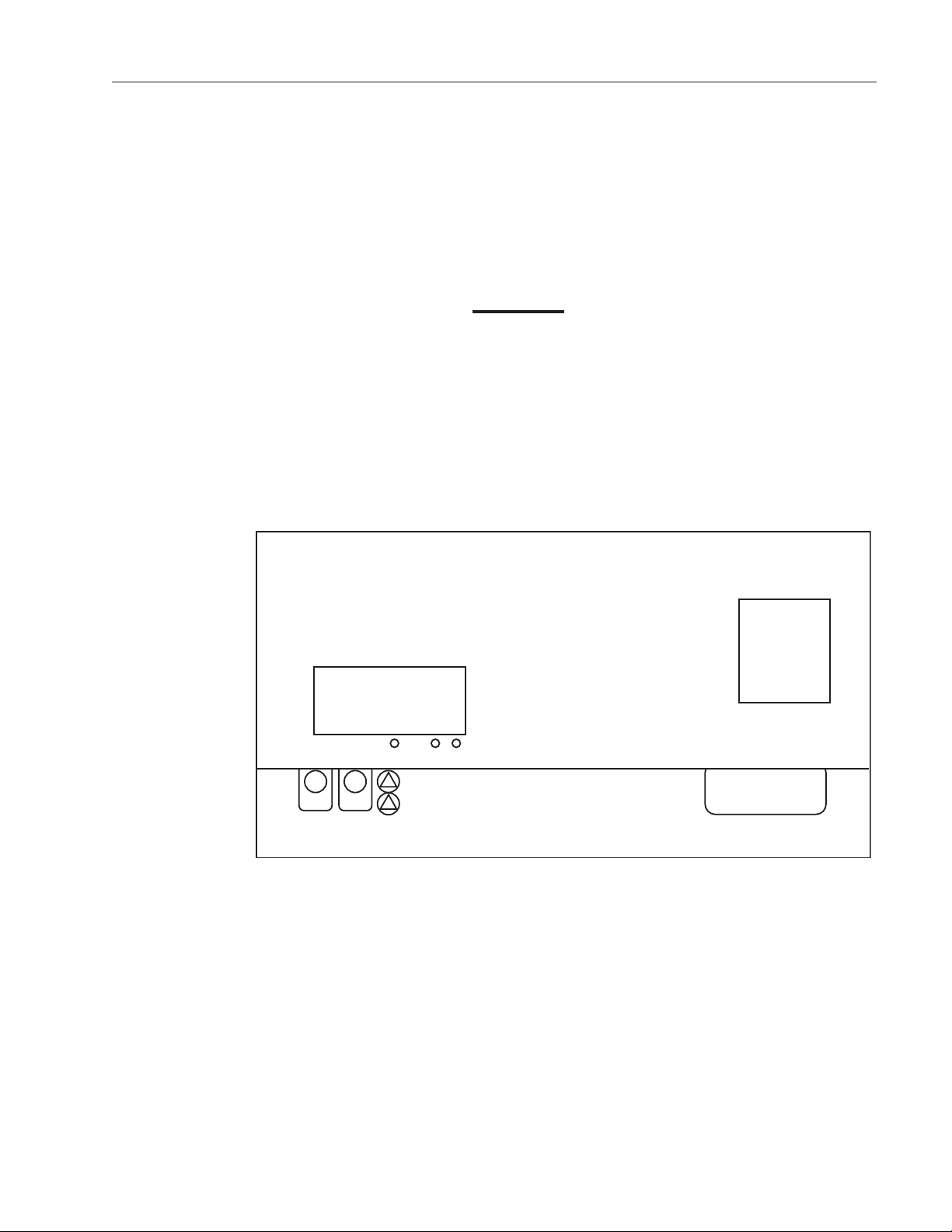
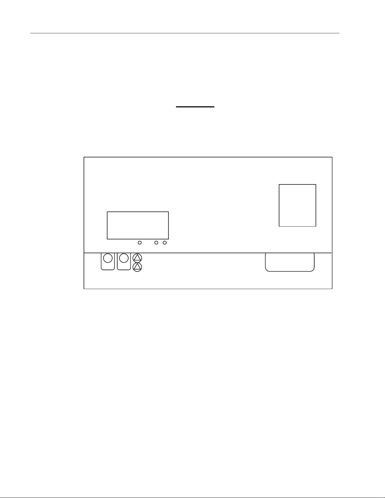
Controls ..............................................................................................................................................................9
Display ..........................................................................................................................................................9
Keypad........................................................................................................................................................10
Operation ..........................................................................................................................................................11
Safety Precautions......................................................................................................................................11
Limit Alarms ................................................................................................................................................12
Display Offsets............................................................................................................................................13
Service ..............................................................................................................................................................14
Replacing the Door asket ........................................................................................................................14
Replacing the Door Handle ........................................................................................................................15
Adjusting the Door Cam ............................................................................................................................16
Accessing the Electronics Compartment....................................................................................................16
Replacing the Heater ..................................................................................................................................17
Replacing the Cooling Fan ........................................................................................................................18
Replacing the Circulating Fan Motor ..........................................................................................................18
Replacing the Controller ............................................................................................................................19
Replacing the Solid State Relay ................................................................................................................20
Replacing the Safety Relay ........................................................................................................................20
Replacing the Control Thermocouple ........................................................................................................21
Troubleshooting ................................................................................................................................................22
Replacement Parts............................................................................................................................................23
Schematic..........................................................................................................................................................24
Warranty ............................................................................................................................................................28
2
Table of Contents

Fisher Isotemp 700 Series premium ovens are available
in three sizes: small (OV700F and OV700 ), medium
(OV701F and OV701 ) and large (OV702F and
OV702 ). All ovens provide PID Microprocessor control
at operating temperatures ranging from 50°C (122°F) to
275°C (527°F).
The forced air ovens provide improved temperature uni-
formity and control, as well as faster drying. In these
ovens, fresh air enters through an air intake on the bot-
tom of the oven, then is heated in a plenum below the
chamber. A blower circulates the heated air into the wall
plenums and the oven chamber itself in uniform flow pat-
terns. Exhaust air is vented through a port at the top of
the oven.
ravity flow ovens inlet air through a port located under
the oven floor. Heat generated convection then gently
moves the air in a vertical circulation pattern. Exhaust air
is vented through a port at the oven top.
Temperature readouts and control parameters are shown
on red LEDs. Three additional LEDs indicate when heater
power is being applied, an error condition is encountered,
or the temperature is being set.
The OV700F and OV700 ovens accommodate a maxi-
mum of five shelves. The OV701F and OV701 ovens
hold eight shelves, while the OV702F and OV702 ovens
each hold eleven.
3
Introduction
Warning
Warnings alert you to a possibility of per-
sonal injury.
Caution
Cautions alert you to a possibility of
damage to the equipment.
Note
Notes alert you to pertinent facts and
conditions.
Hot Surface
Hot surfaces alert you to a possibility of
personal injury if you come in contact
with a surface during use or for a period
of time after use.
Alert Signals

Isotemp ovens incorporate a variety of safety features. A
safety backup is built into the controller software: if the
primary heater control fails, the backup will maintain con-
trol at 5°C above the set point. An alarm LED then indi-
cates that the backup controller is operating the oven. A
circuit breaker protects the oven from power surges. If pri-
mary and backup heater controls fail, an independent
Over Temperature Device will disengage heater opera-
tion. The silicon rubber gasket supplied with the oven is
good for continuous use up to 250°C and intermittent use
to 275°C. This gasket provides a better seal than the high
temperature gasket and is supplied with is supplied with
the unit. An optional high temperature braided gasket is
available for customers using the oven frequently above
250°C. The part numbers of the supplied and optional
gasket are listed below:
4
INTRODUCTION
Oven Silicon Rubber asket Part # Braided asket Part #
(Supplied with Oven) (High Temp asket Optional)
OV700F, OV700 SPN 101908 SPN 95782
OV701F, OV701 SPN 101909 SPN 95783
OV702F, OV702 SPN 101910 SPN 95784

5
Performance Characteristics
Operating Range 50 to 275°
Average Uniformity @ 200°*
Forced Air Ovens +/-3°C
ravity Ovens +/-4°C
Control Resolution 1°C
Control Sensitivity +/-0.5°C
Recovery Time @ 200°C**
OV700F 1.0 minutes
OV700 2.0 minutes
OV701F 2.0 minutes
OV701 3.0 minutes
OV702F 2.5 minutes
OV702 4.0 minutes
Rise Time to 275°C
OV700F 70 minutes
OV700 40 minutes
OV701F 80 minutes
OV701 80 minutes
OV702F 80 minutes
OV702 100 minutes
Air Exchanges per Hour*
OV700F 43
OV700 24
OV701F 29
OV701 16
OV702F 22
OV702 12
BTU/hr Output @100°C @200°C
OV700F 1125 2750
OV700 470 1325
OV701F 1325 2925
OV701 1040 2025
OV702F 1325 3095
OV702 1150 2040
*as per ASTM E145
**door open one minute
Specifications

Electrical Requirements
OV700F ovens
13-247-725F 120 V, 11.5A, 1380W, 60 Hz
13-247-726F 240 V, 5.8A, 1392W, 50/60 Hz
OV700 ovens
13-247-725 120 V, 11A, 1320W, 60Hz
13-247-726 240 V, 5.5A, 1320W, 50/60Hz
OV701F ovens
13-247-737F 120 V, 15.5A, 1860W, 60 Hz
13-247-738F 240 V, 7.8A, 1870W, 50/60 Hz
OV701 ovens
13-247-737 120 V, 15A, 1800W, 60Hz
13-247-738 240 V, 7.5A, 1800W, 50/60Hz
OV702F ovens
13-247-750F 120 V, 15.5A, 1860W, 60 Hz
13-247-751F 240 V, 7.8A, 1872W, 50/60 Hz
OV702 ovens
13-247-750 120 V, 15A, 1800W, 60Hz
13-247-751 240 V, 7.5A, 1800W, 50/60Hz
Chamber Volumes
OV700F & OV700 ovens 2.5 cu ft
OV701F & OV701 ovens 3.8 cu ft
OV702F & OV702 ovens 5.0 cu ft
Chamber Dimensions (W x D x H)
OV700F & OV700 ovens 18 x 18 x 13.5 in
OV701F & OV701 ovens 18 x 18 x 20 in
OV702F & OV702 ovens 18 x 18 x 26.5 in
Environmental Conditions
Operating: 17°C to 27°C; 20% to 80% relative humidity,
non-condensing.
Installation category II (overvoltage) in accor-
dance with IEC 664.
Pollution degree 2 in accordance wth IEC 664.
Altitude Limit: 2,000 meters.
Storage: -25°C to 65°C 10% to 85% relative humidity
6
SPECIFICATIONS

7
7
Selecting a Location
The oven requires an area approximately 2 ft. x 2 ft. The
bench selected must be capable of supporting at least 120
lbs. for the OV700F and OV700 ovens, 130 lbs. for
the OV701F and OV701 ovens, or 135 lbs. for the OV702F
and OV702 ovens. Proper electrical power must be avail-
able. Locate the oven such that no extension cord is
required. The oven shall have a 2” air clearance on all sides
(6” if combustible materials) and a minimum of 24” air clear-
ance on top to allow heat dissipation and prevent tempera-
ture build ups.
Unpacking
Fisher Isotemp®ovens are shipped in a single carton. After
unpacking, locate each item shown in the list below. Report
any missing items, by name and part number, to your Fisher
branch. In the event of shipping damage, retain the shipping
material and file a claim with the final carrier.
Item
Oven Assembly
OV700F & OV700 (small)
120 V, 50/60 Hz
240 V, 50/60 Hz
OV701F & OV701 (medium)
120 V, 50/60 Hz
240 V, 50/60 Hz
OV702F & OV702 (large)
120 V, 50/60 Hz
240 V, 50/60 Hz
Shelves
OV700F, OV700 , OV701F, OV701 (one provided)
OV702F, OV702 (two provided)
Shelf Supports
OV700F, OV700 , OV701F, OV701 (two provided)
OV702F, OV702 (four provided)
Instruction Manual
Installation
Note
If the equipment is used in a manner
not specified by the manufacturer,
the protection provided by the equip-
ment may be impaired.
Hot Surface
Oven vent and exiting air are hot.
Keep hands away.
Warning
Do not use top of oven as a shelf.
Do not cover oven vent hole.
Keep combustible materials away
from oven vent hole.

Preparing the Oven
To prepare the oven for operation, perform the following
procedures:
1. Install the shelf.
2. Make certain all packing material has been
removed from oven chamber.
3. Connect the line cord to an appropriate electri-
cal outlet.
4. The oven is now ready for operation. No prelimi-
nary adjustments or calibrations are required.
Depending on the customer application and cus-
tomer laboratory procedures an initial calibration
may be done at this point. (See Display Off-
sets)
Power Switch
The 700 Series ovens feature a front panel mounted
power switch which is a Switch combination power switch
and circuit breaker, eliminating the need for separate
fusing. The circuit breaker will interrupt power in the event
of an oven heater malfunction. Press the I (upper) half of
the rocker-type power switch to the in position to turn the
oven on. Press the 0 (lower) half to the in position to turn
off oven power. To reset the breaker, first place the switch
to the off position, then return it to the on position.
INSTALLATION
Caution
See data plate on oven for voltage,
current and line frequency specifica-
tions. Check that the power require-
ments of the oven will not overload the
circuit to which it will be connected.
8

The following sections briefly describe the locations and
functions of various display fields and keypad controls.
More detailed descriptions are provided, when required,
in the operating sections of the manual.
Display
The 700 Series controller features a bright, one-half inch
LED numeric display which reads out the oven tempera-
ture. Three smaller LEDs indicate, respectively, an alarm
condition, that power is being applied to the oven heaters
or that the control temperature is being set. Each display
field is discussed separately below.
Controls
°C
Program Alarm Heat
Power
On
Off
Isotemp
Oven
Menu Set
Increase
Decrease
Figure 1: Display Fields
Temperature Display In the normal operating mode, shows the current oven
temperature. During programming, indicates the oven set
temperature target.
Heat Indicator Lights when power is being supplied to the oven heater.
Alarm Indicator Lights if the actual oven temperature exceeds the alarm
temperature. The alarm temperature is factory-adjusted
to be 5°C above the set temperature.
Program Indicator Lights when the control temperature is being set.
9

10
Keypad
The 700 Series incorporates a four-key, tactile keypad.
The function of each key is discussed individually below.
CONTROLS
°C
Program Alarm Heat
Power
On
Off
Isotemp
Oven
Menu Set
Increase
Decrease
Figure 2: The Keypad
Pressing MENU while holding down the SET key decreases the oven set temperature,
as indicated on the temperature display.
Pressing INCREASE while holding down the SET key increases the oven set tempera-
ture, as indicated on the temperature display.
Pressing DECREASE while holding down the SET key decreases the oven set
temperature, as indicated on the temperature display.
Pressing SET causes the display to show the set temperature. Used with INCREASE
and DECREASE to change the set temperature. With MENU to access entry of a tem-
perature display offset.

11
The 700 Series ovens maintain a set temperature until that
set temperature is changed. To set a temperature, perform
the following:
1. Place the power switch in the ON position. All 8s will
flash as a test of the display.
2. Press and hold the SET.
3. Observe the set temperature in the display window.
4. To decrease the set temperature, press DECREASE
while holding SET.
5. To increase the set temperature, press INCREASE
while holding SET.
6. When the desired set temperature is shown, release
the INCREASE or DECREASE keys. Finally, release
the SET key. The oven automatically begins to con-
trol at the set temperature.
Safety Precautions
• This unit is not explosion proof. Do not use in the
presence of flammable or combustible materials;
Fire or explosion may result. Unit contains compo-
nents that may ignite such materials. Before operat-
ing ovens, always observe the following safety pre-
cautions:
• Fumes and spillage from acidic solutions cause cor-
rosion of the stainless steel chamber. Care should
be taken to maintain a neutral PH at all times.
• The heater for the unit is in the bottom of the unit.
Surface temperatures at the bottom cover of the unit
may be higher than set point temperature. For
example: A plastic container on the heater cover
may become hot enough to melt/burn the container
at settings below the melting point of plastic. Do not
place items on the heater cover.
• Wear insulated gloves.
• Use tongs.
• Never stand in front of an open oven.
• Use safety goggles.
Operation
Note
To rapidly increase or decrease
the set temperature press and
hold the appropriate arrow key.
To slowly increment or decre-
ment the set temperature one
degree at a time, press and
immediately release the arrow
key.

12
Limit Alarms
The 700 Series controllers feature a deviation alarm
which alerts the operator and and interrupts heater power
whenever the actual oven temperature differs from the
set temperature by more than 5°C. The set limit is built in
to the controller and cannot be changed.
• If the actual temperature exceeds the alarm
limit, the alarm indicator LED will light and the
display will indicate EEE.
• The reference point for the alarm is the set tem-
perature. Any change in the set temperature will
cause a corresponding shift in the alarm temper-
ature.
Example:If the set temperature is 150°C, the
alarm will trip at 155°C. If the set temperature is
changed to 200°C, the alarm will follow the set
temperature and trip at 205°C.
• Changing the set temperature to a value more
than 5°C below the present oven temperature
will trip the alarm. Power is removed from the
heaters when an alarm condition occurs.
Example: First experiment samples were being
soaked at 160°C. Experiment completed and
oven reset to 140°C. The oven immediately
goes in to alarm once the set point is reset to
140 from 160. The oven will stay in alarm until
the oven temperature cools down to 144.9°
(140+5-.1).
OPERATION

Display Offsets
The 700 Series controllers permit the operator to select a
display offset Offsets temperature. With a display offset
entered, the temperature displayed will be the actual oven
temperature (measured at the control thermocouple) plus
or minus the display offset selected. Functionally, the off-
set feature permits the operator to measure and calibrate
such that the display will indicate the temperature at a
specific point or zone within the oven. To enter a display
offset, carry out the following steps:
1. Press the MENU, the display will indicate CAL
2. To view the present offset value, press and hold
the SET key.
3. To change the display offset, press and hold the
SET key. Press INCREASE or DECREASE until
the display indicates the desired offset.
4. Release the SET key.
5. Press MENU once to return to normal tempera-
ture control.
Examples:
1. The displayed temperature is the result of alge-
braically adding the actual temperature to the
offset value. Thus, if an offset of -3 degrees is
being used, a measured temperature of 50
degrees will be displayed as 47 degrees.
2. A test is to be performed at 150°C in the center
of the oven and temperature is critical. Place a
thermometer or thermocouple (calibrated) at the
critical point and set the oven to 150°C and
allow the oven to stabilize. The calibrated ther-
mometer reads 151°C. A display offset of 1 is
entered. The immediate display reads 151. The
oven cools to 150°C the display reads 150 and
the calibrated thermometer reads 150.
13
OPERATION

The following sections describe procedures for servicing
the 700 Series ovens. The first procedure, Replacing the
Door asket, may be performed by most users. However,
all other service procedures involve potential exposure to
line voltage. These procedures should be undertaken only
by qualified service personnel. The second section,
Accessing the Electronics Compartment, describes proce-
dures required for subsequent service sections and is ref-
erenced by these later sections when required.
In the event service is required beyond that available by
the customer, or for warranty service, contact Fisher
Service Dept. at 1-800-395-5442.
For technical assistance call 1-800-926-0505.
Replacing the Door asket
The Isotemp 700 Series ovens incorporate a durable, sili-
cone door gasket to minimize heat loss. Should the gas-
ket become defective or be damaged, it may be replaced
by following the procedures below.
1. Set the power switch to off position and open
chamber door.
2. Open door fully. Carefully remove
and retain
hardware from door hinges (case side). Lay
door on a flat surface with the handle over the
edge.
3. Note the joint position of the old gasket. This is
where the new gasket installation will start.
NOTE: Study the method of door gasket attachment
before starting disassembly. This understanding will avoid
confusion later in this process.
4. Bend back the old door gasket and remove the
Phillips head screws attaching the gasket.
5. Remove the old door gasket.
6. Loosely install two screws through the stainless
steel liner and into the door wrap to align these
pieces.
7. Begin installing the replacement gasket at the
joint position of the old gasket. Stretch the
Service
Caution
Service procedures requiring
access to the electronics compart-
ment involve exposure to line volt-
age and should be done only by
qualified service personnel.
Disconnect oven from power
source before attempting repairs.
Caution
Allow oven to cool to ambient temper-
ature before attempting repair.
Caution
Only factory authorized compo-
nents should be used for all repairs.
Failure to use factory authorized
replacement components will void
warranty and could result in unit
malfunction and or hazardous oper-
ating conditions.
14

SERVICE
Caution
Allow oven to cool to ambient tempera-
ture before attempting repair.
15
replacement gasket around the corners of the
liner to avoid bunching up of the gasket materi-
al.
8. Install a Phillips head screw as the gasket
rounds each corner to keep the gasket properly
stretched. (The screw goes through the liner,
pierces the gasket and threads into the door
wrap.)
9. After all four corners are secured, install the
remainder of the Phillips head screws. Make
sure there is no gap at the gasket joint; stretch
the gasket slightly if necessary.
10. Reinstall the door onto the case with hinges.
Replacing the Door Handle
To replace a defective door handle, perform the steps
below: NOTE: See caution above.
1. Remove the two mounting screws holding latch
cover in place.
2. Remove the two mounting screws holding
defective handle in place.
3. Mount the replacement handle using two
screws.
4. Adjust bottom nut (13/16) from end of shaft.
5. Secure latch cover in place with two screws.
Adjusting the Door Cam
Due to handling in shipment or to heat distortion with use,
the door cam may require adjustment. To facilitate proper
closing and sealing of door, steps 1 through 6 may have
to be performed concurrently.
To adjust the door cam, perform the following:
1. Open door and remove screws holding latch
cover in place.

SERVICE
Caution
Service procedures requiring access to
the electronics compartment involve
exposure to line voltage and should be
done only by qualified service person-
nel. Disconnect oven from power
source before attempting repairs.
16
2. Locate nuts securing tongue on cam shaft.
3. Loosen but do not remove outside nut.
4. Adjust inside nut, one full turn clockwise draws
door 1/16” closer to cabinet when door is
closed.
5. Secure cam tongue in place by tightening out-
side nut.
6. Secure latch cover in place with two screws.
Accessing the Electronics
Compartment
To access the electronics compartment, proceed as fol-
lows: (See sketch on next page.)
1. Disconnect power cord from the electrical outlet.
2. Open the chamber door. Carefully remove
and
retain
hardware from door hinges (case side).
Set door aside.
3. Slide the oven forward until the front of the
bezel (control panel) is at least three inches
from the edge of the bench top (or the oven feet
are at the edge of the bench).
4. Prop up the oven front by placing a shim under
each front foot. Use shims between one and
one-half and two inches in thickness.
5. Remove the screws securing bezel from bottom
of oven.
6. Slide the oven back on the table plus a few
inches (to set the bezel on the bench) and
rotate the bottom of the bezel out from the oven.
The top clips will come loose but the wiring will
still be connected.
7. Carefully set the bezel on the bench.

Replacing the Heater
To replace a defective heater, proceed as follows:
1. Disconnect power cord from the electrical outlet.
2. Remove the two screws that secure the heater
cover. Remove the cover by lifting and sliding it
forward. It may be necessary to use a flat-blade
screwdriver to assist in lifting the cover upward.
Set heater cover aside.
3. Remove the two nuts and shake proof washers
securing the heater leads, then pull the lead ter-
minals off the heater studs.
4. Remove the two screws securing heater to cabi-
net. Slide heater forward to disengage back
heater clips, lift back of heater up, then slide
heater back and lift out.
5. Install replacement heater and reassemble oven
by generally reversing the steps above.
SERVICE
Heater
Electronics
Compartment
(Open)
Bezel/Control
Panel
Heater
Cover
Front
Face
Fascia
Bezel
Bottom
Screws
Caution
Allow oven to cool to ambient tempera-
ture before attempting repair.
Caution
Service procedures requiring access to
the electronics compartment involve
exposure to line voltage and should be
done only by qualified service person-
nel. Disconnect oven from power
source before attempting repairs.
17

SERVICE
Note
When installing the replacement fan,
make certain air flow arrow molded
into fan housing points
into
the oven
chassis.
Caution
Sheet metal in this area is sharp.
Work carefully.
18
Replacing the Cooling Fan
To replace a defective cooling fan, proceed as follows:
1. Complete the procedures discussed in
Accessing the Electronics Compartment.
2. Remove the two fan power wires from push-on
terminals located on fan housing.
3. Remove the three mounting screws holding the
fan in place.
4. Install replacement fan and reassemble oven by
generally reversing the steps above.
Replacing the Circulating Fan
Motor
To replace a defective circulating fan motor, proceed as
follows:
1. Complete the procedures discussed in
Accessing the Electronics Compartment and
Replacing the Heater steps 1 & 2 (remove the
heater cover). Note and observe all Caution
statements.
2. Using an Allen wrench, loosen set-screw holding
the fan blade onto the motor shaft. Observe the
shaft has a flat side to prevent the set-screw
from turning on the shaft.
3. Locate the two electrical leads from the fan
motor. Remove the leads from the push-on ter-
minal strip located in the front of the oven bezel.
4. Lay the oven on its back with the oven bottom
facing forward.
5. Detach the controller housing (oven bottom) by
removing the eight screws which fasten it to the
cabinet. Two screws are located on each side of
the oven and four on the bottom of the oven.
6. Locate the two access holes for the motor

SERVICE
Caution
Allow oven to cool to ambient tempera-
ture before attempting repair.
Caution
Service procedures requiring access to
the electronics compartment involve
exposure to line voltage and should be
done only by qualified service person-
nel. Disconnect oven from power
source before attempting repairs.
19
mounting nuts located in the oven floor, in front
of and in back of the motor shaft.
7. Push an 11/32-in nut driver through the front
access hole, gently pushing aside the oven
insulation until the nut driver reaches the front
motor mounting nut.
8. Remove front nut and washer, then repeat
process using back access hole to remove back
motor mounting nut and washer.
9. Remove the fan motor by sliding it out.
10. Install replacement fan motor by generally
reversing the steps above.
Replacing the Controller
To replace a defective controller, proceed as follows:
1. Complete the procedures discussed in
Accessing the Electronics Compartment.
2. Locate terminal blocks on controller, remove all
wires connected to controller. Note color and
location of wires.
3. Remove four screws that hold controller to
bezel, then remove old controller.
4. Install new replacement controller and reattach
wires previously removed.
5. Check wiring connections against schematic,
making sure that the line power wire is attached
to the proper terminal, i.e., 120V or 240V.
6. Check switch DS1 setting: If forced air, set
switch A to ON, otherwise; set to OFF for gravi-
ty. Switch B should always be OFF.

SERVICE
Caution
Allow oven to cool to ambient tempera-
ture before attempting repair.
Caution
Service procedures requiring access to
the electronics compartment involve
exposure to line voltage and should be
done only by qualified service person-
nel. Disconnect oven from power
source before attempting repairs.
20
Replacing the Solid State Relay
To replace a defective solid state relay, proceed as fol-
lows:
1. Complete the procedures discussed in
Accessing the Electronics Compartment.
2. Consult the schematic and locate the solid state
relay (mounted on bezel).
3. Remove four lead wires from their screw-down
terminals.
4. Remove two Phillips screws which mount the
solid state relay to the bezel.
5. Lift out the solid state relay. Put new solid state
relay in place, making certain that the thin, con-
ductive pad remains between the solid state
relay and the bezel.
6. enerally reverse the steps above to re-assem-
ble oven.
Replacing the Safety Relay
To replace a defective safety relay, proceed as follows:
1. Complete the procedures discussed in
Accessing the Electronics Compartment.
2. Consult the schematic and locate the safety
relay (mounted on bezel).
3. Remove four lead wires from their push-on ter-
minals.
4. Remove two Phillips screws which mount the
safety relay to the bezel.
5. Lift out the safety relay.
6. enerally reverse the steps above to install the
replacement safety relay and re-assemble oven.
This manual suits for next models
18
Table of contents
Other Fisher Scientific Oven manuals
Popular Oven manuals by other brands

Bosch
Bosch CMG633B 1I Series instruction manual

Bosch
Bosch HBG5575.0A User manual and installation instructions

Nordmende
Nordmende CTEC50BK Operating and installation instructions

Princess
Princess 112371 manual

Leonard
Leonard LBN1310X user manual

Bosch
Bosch HNG978Q 1A Series User manual and installation instructions