Fisher Scientific Isotemp Premium 700 Series User manual

Isotemp®Premium Ovens
700 Series
Operation Manual and Parts List
LT2148X1 (7006916) Rev. 3
© 2010 Fisher Scientific Inc.
All rights reserved
Printed in U.S.A.
Isotemp

Fisher Scientific
MANUAL NUMBER LT2148X1 (7006916)
3 30485 10/29/13 Corrected Menu button details - pg 4-2
2 28232 2/23/12 Updated Recovery and Rise Time - pg 2-2 ccs
1 27703 7/27/11 Corrected PC board and probe number in parts list ccs
0 -- 4/26/10 Transfer to Marietta (was LT2148X1 2/9/09) ccs
REV ECR/ECN DATE DESCRIPTION By
Preface
Isotemp Premium Ovens i
Models covered in this manual
Model Size Voltage Forced Air/Gravity
13247725F (6916) Small (2.5 cu ft) 120V Forced Air
13247725G (6917) Small (2.5 cu ft) 120V Gravity
13247726F (6918) Small (2.5 cu ft) 240V Forced Air
13247726G (6919) Small (2.5 cu ft) 240V Gravity
13247737F (6921) Medium (3.8 cu ft) 120V Forced Air
13247737G (6922) Medium (3.8 cu ft) 120V Gravity
13247738F (6923) Medium (3.8 cu ft) 240V Forced Air
13247738G (6924) Medium (3.8 cu ft) 240V Gravity
13247750F (6925) Large (5 cu ft) 120V Forced Air
13247750G (6926) Large (5 cu ft) 120V Gravity
13247751F (6927) Large (5 cu ft) 240V Forced Air
13247751G (6928) Large (5 cu ft) 240V Gravity

Fisher Scientificii Isotemp Premium Ovens
Preface
Important Read this instruction manual. Failure to read, understand and follow the instructions in this manual
may result in damage to the unit, injury to operating personnel, and poor equipment performance. s
Caution All internal adjustments and maintenance must be performed by qualified service personnel. s
Material in this manual is for information purposes only. The contents and the product it describes are subject
to change without notice. Fisher Scientific makes no representations or warranties with respect to this manual.
In no event shall Fisher Scientific be held liable for any damages, direct or incidental, arising out of or related
to the use of this manual.
©2010 Fisher Scientific. All rights reserved.

Fisher Scientific Isotemp Premium Ovens iii
Preface
Important operating and/or maintenance instructions. Read the accompanying text carefully.
Potential electrical hazards. Only qualified persons should perform procedures associated with this
symbol.
Equipment being maintained or serviced must be turned off and locked off to prevent possible injury.
Hot surface(s) present which may cause burns to unprotected skin, or to materials which may be
damaged by elevated temperatures.
Marking of electrical and electronic equipment, which applies to electrical and electronic equipment
falling under the Directive 2002/96/EC (WEEE) and the equipment that has been put on the market
after 13 August 2005.
This product is required to comply with the European Union’s Waste Electrical & Electronic
Equipment (WEEE) Directive 2002/96/EC. It is marked with the WEEE symbol. Fisher Scientific has
contracted with one or more recycling/disposal companies in each EU Member State European
Country, and this product should be disposed of or recycled through them. Further information on
compliance with this directive, the recyclers in your country and information on Fisher Scientific
products will be available at www.fishersci.com.
4Always use the proper protective equipment (clothing, gloves, goggles, etc.)
4Always dissipate extreme cold or heat and wear protective clothing.
4Always follow good hygiene practices.
4Each individual is responsible for his or her own safety.

Fisher Scientificiv Isotemp Premium Ovens
Preface
Do You Need Information or Assistance
on Fisher Scientific Equipment?
The Fisher Scientific Sales Group can provide information on pricing and give you
quotations. We can take your order and provide delivery information on major equipment items or
make arrangements to have your local sales representative contact your. Our products are listed on
the internet and we can be contacted through our Internet home page.
1-800-766-7000 Customer Service
www.fishersci.com To order online
Fisher Scientific Product Service Support can supply technical information about proper
setup, operation or troubleshooting of your equipment. We can fill your needs for replacement parts
or provide you with on-site service. We can also provide you with a quotation on our Extended
Maintenance Program for our products.
Whatever products you need or use, we will be happy to discuss your applications. If you are
experiencing technical problems, working together, we will help you locate the problem and, chances
are, correct it yourself...over the telephone without a service call.
When more extensive service is necessary, we will assist you with direct factory trained
technicians or a qualified service organization for on-the-spot repair. If your service need is covered
by the Fisher Scientific Products warranty, we will arrange for the unit to be repaired at our expense
and to your satisfaction.
Regardless of your needs, professional service technicians are available by telephone to assist
you concerning our products Monday through Friday from 8:00 a.m. to 6:00 p.m. Eastern Time.
Please call or fax us at:
1-800-766-7000 Customer Service
1-800-926-1166 Orders Fax
International customers, please contact your local Fisher Scientific distributor.

Isotemp Premium Ovens vFisher Scientific
Table of Contents
Introduction . . . . . . . . . . . . . . . . . . . . . . . . . . . . . . . . . . . . . . . . . . . . . . . . .1-1
Specifications . . . . . . . . . . . . . . . . . . . . . . . . . . . . . . . . . . . . . . . . . . . . . . .2-1
Installation . . . . . . . . . . . . . . . . . . . . . . . . . . . . . . . . . . . . . . . . . . . . . . . . . .3-1
Unpacking . . . . . . . . . . . . . . . . . . . . . . . . . . . . . . . . . . . . . . . . . . . . .3-1
Power Switch . . . . . . . . . . . . . . . . . . . . . . . . . . . . . . . . . . . . . . . . . . .3-2
Preparing the Oven . . . . . . . . . . . . . . . . . . . . . . . . . . . . . . . . . . . . . .3-2
Controls . . . . . . . . . . . . . . . . . . . . . . . . . . . . . . . . . . . . . . . . . . . . . . . . . . . . .4-1
Display . . . . . . . . . . . . . . . . . . . . . . . . . . . . . . . . . . . . . . . . . . . . . . . .4-1
Keypad . . . . . . . . . . . . . . . . . . . . . . . . . . . . . . . . . . . . . . . . . . . . . . . .4-2
Operation . . . . . . . . . . . . . . . . . . . . . . . . . . . . . . . . . . . . . . . . . . . . . . . . . . . .5-1
Safety Precautions . . . . . . . . . . . . . . . . . . . . . . . . . . . . . . . . . . . . . . .5-1
Limit Alarms . . . . . . . . . . . . . . . . . . . . . . . . . . . . . . . . . . . . . . . . . . .5-2
Display Offsets . . . . . . . . . . . . . . . . . . . . . . . . . . . . . . . . . . . . . . . . . .5-3
Service . . . . . . . . . . . . . . . . . . . . . . . . . . . . . . . . . . . . . . . . . . . . . . . . . . . . . .6-1
Replacing the Door Handle . . . . . . . . . . . . . . . . . . . . . . . . . . . . . . . .6-2
Replacing the Door Gasket . . . . . . . . . . . . . . . . . . . . . . . . . . . . . . . .6-2
Accessing Electronics Compartment . . . . . . . . . . . . . . . . . . . . . . . . . .6-3
Adjusting Door Cam . . . . . . . . . . . . . . . . . . . . . . . . . . . . . . . . . . . . .6-3
Replacing the Heater . . . . . . . . . . . . . . . . . . . . . . . . . . . . . . . . . . . . .6-4
Replacing the Cooling Fan . . . . . . . . . . . . . . . . . . . . . . . . . . . . . . . . .6-5
Replacing the Circulating Fan Motor . . . . . . . . . . . . . . . . . . . . . . . . .6-6
Replacing the Controller . . . . . . . . . . . . . . . . . . . . . . . . . . . . . . . . . .6-7
Replacing the Solid State Relay . . . . . . . . . . . . . . . . . . . . . . . . . . . . .6-8
Replacing the Control Thermocouple . . . . . . . . . . . . . . . . . . . . . . . .6-9
Rerplacing the Safety Relay . . . . . . . . . . . . . . . . . . . . . . . . . . . . . . . .6-9
Troubleshooting . . . . . . . . . . . . . . . . . . . . . . . . . . . . . . . . . . . . . . . . . . . . . .7-1
Replacement Parts . . . . . . . . . . . . . . . . . . . . . . . . . . . . . . . . . . . . . . . . . . .8-1
Schematic . . . . . . . . . . . . . . . . . . . . . . . . . . . . . . . . . . . . . . . . . . . . . . . . . . .9-1
Section 1
Section 2
Section 3
Section 4
Section 5
Section 6
Section 8
Section 7
Section 9


Isotemp Premium Ovens 1-1Fisher Scientific
Section 1 Introduction
Fisher Scientific Isotemp 700 Series Standard ovens are available in three
sizes: Small, Medium and Large. All ovens provide PID Microprocessor
control at operating temperatures ranging from 50°C (122°F) to 275°C
(527°F).
The forced air ovens provide improved temperature uniformity and
control, as well as faster drying. In these ovens, fresh air enters through an
air intake on the bottom of the oven, then is heated in a plenum below the
chamber. A blower circulates the heated air into the wall plenums and the
oven chamber itself in uniform flow patterns. Exhaust air is vented
through a port at the top of the oven.
Gravity flow ovens inlet air through a port located under the oven floor.
Heat generated convection then gently moves the air in a vertical
circulation pattern. Exhaust air is vented through a port at the oven top.
Temperature readouts and control parameters are shown on red LEDs.
Three additional LEDs indicate when heater power is being applied, an
error condition is encountered, or the temperature is being set.
The Small ovens accommodate a maximum of five shelves. The Medium
ovens hold eight shelves, while the Large ovens each hold eleven.
Isotemp ovens incorporate a variety of safety features. A safety backup is
built into the controller software: if the primary heater control fails, the
backup will maintain control at 5°C above the set point. An alarm LED
then indicates that the backup controller is operating the oven. A circuit
breaker protects the oven from power surges. If primary and backup heater
controls fail, an independent Over Temperature Device will disengage
heater operation.
The silicon rubber gasket supplied with the oven is good for continuous
use up to 250°C and intermittent use to 275°C. This gasket provides a
better seal than the high temperature gasket and is supplied with is
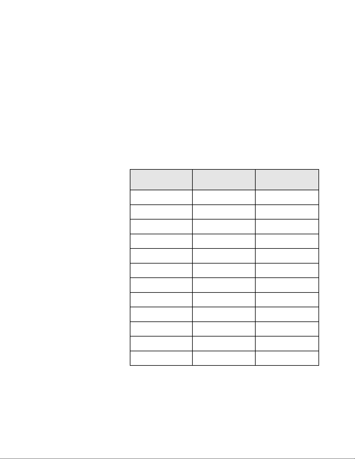
supplied with the unit. An optional high temperature braided gasket is
available for customers using the oven frequently above 250°C. The part
numbers of the supplied and optional gasket are listed below:
Oven Size Silicon Rubber Gasket Part #
(Supplied with Oven)
Braided Gasket Part #
(High Temp Gasket Optional)
Small SPN 101908 SPN 95782
Medium SPN 101909 SPN 95783
Large SPN 101910 SPN 95784


Isotemp Premium Ovens 2-1Fisher Scientific
Section 2 Specifications
Performance Characteristics
Operating Range . . . . . . . . . . . . . . . . . .50 to 275°C
Average Uniformity @ 200°C
Forced Air Ovens . . . . . . . . . . . . . . . . . . . . . .±3°C
Gravity Ovens . . . . . . . . . . . . . . . . . . . . . . . . .±4°C
Resolution . . . . . . . . . . . . . . . . . . . . . . . . . . . . .1°C
Control Sensitivity . . . . . . . . . . . . . . . . . . . . .±0.5°C
Model Size Forced Air/ Gravity
13247725F (6916) Small (2.5 cu ft) Forced Air
13247725G (6917) Small (2.5 cu ft) Gravity
13247726F (6918) Small (2.5 cu ft) Forced Air
13247726G (6919) Small (2.5 cu ft) Gravity
13247737F (6921) Medium (3.8 cu ft) Forced Air
13247737G (6922) Medium (3.8 cu ft) Gravity
13247738F (6923) Medium (3.8 cu ft) Forced Air
13247738G (6924) Medium (3.8 cu ft) Gravity
13247750F (6925) Large (5 cu ft) Forced Air
13247750G (6926) Large (5 cu ft) Gravity
13247751F (6927) Large (5 cu ft) Forced Air
13247751G (6928) Large (5 cu ft) Gravity

2-2 Isotemp Premium Ovens Fisher Scientific
Section 2
Specifications
Recovery Time @ 200°C**
Small ovens - forced air . . . . . . . . . . . .6.0 minutes
Small ovens - gravity . . . . . . . . . . . . .10.0 minutes
Medium ovens - forced air . . . . . . . . . .6.0 minutes
Medium ovens - gravity . . . . . . . . . . .10.0 minutes
Large ovens - forced air . . . . . . . . . . . .8.0 minutes
Large ovens - gravity . . . . . . . . . . . . .16.0 minutes
Rise Time to 275°C
Small ovens - forced air . . . . . . . . . . . .50 minutes
Small ovens - gravity . . . . . . . . . . . . . . .45 minutes
Medium ovens - forced air . . . . . . . . . . .50 minutes
Medium ovens - gravity . . . . . . . . . . . . .40 minutes
Large ovens - forced air . . . . . . . . . . . . .70 minutes
Large ovens - gravity . . . . . . . . . . . . . . .60 minutes
Air Exchanges per hour*
Small ovens - forced air . . . . . . . . . . . . . . . . . . . .43
Small ovens - gravity . . . . . . . . . . . . . . . . . . . . . .24
Medium ovens - forced air . . . . . . . . . . . . . . . . .29
Medium ovens - gravity . . . . . . . . . . . . . . . . . . .16
Large ovens - forced air . . . . . . . . . . . . . . . . . . . .22
Large ovens gravity . . . . . . . . . . . . . . . . . . . . . . .12
BTU/hr Output . . . . . . . . . . . . . . . . . . . . .@100°C @200°C
Small ovens - forced air . . . . . . . . . . . . . . . . . .1125 2750
Small ovens - gravity . . . . . . . . . . . . . . . . . . . . .470 1325
Medium ovens - forced air . . . . . . . . . . . . . . .1325 2925
Medium ovens - gravity . . . . . . . . . . . . . . . . .1040 2025
Large ovens - forced air . . . . . . . . . . . . . . . . . .1325 3095
Large ovens - gravity . . . . . . . . . . . . . . . . . . . .1150 2040
*as per ASTM E145
**door open one minute
Note Temperature Recovery Times and Temperature Rise times are based
on a nominal line voltage of either 120VAC or 240VAC, and on ovens
pre-calibrated to 200°C and 275°C. s

Electrical Requirements
Small ovens
13-247-725F . . . . . . .120V, 11.5A, 1380W, 60 Hz
13-247-726F . . . . .240V, 5.8A, 1392W, 50/60 Hz
Small ovens
13-247-725G . . . . . . . .120V, 11A, 1320W, 60 Hz
13-247-726G . . . . .240V, 5.5A, 1320W, 50/60 Hz
Medium ovens
13-247-737F . . . . . . .120V, 15.5A, 1860W, 60 Hz
13-247-738F . . . . .240V, 7.8A, 1870W, 50/60 Hz
Medium ovens
13-247-737G . . . . . . . .120V, 15A, 1800W, 60 Hz
13-247-738G . . . . .240V, 7.5A, 1800W, 50/60 Hz
Large ovens
13-247-750F . . . . . . .120V, 15.5A, 1860W, 60 Hz
13-247-751F . . . . .240V, 7.8A, 1872W, 50/60 Hz
Large ovens
13-247-750G . . . . . . . .120V, 15A, 1800W, 60 Hz
13-247-751G . . . . .240V, 7.5A, 1800W, 50/60 Hz
Chamber Volumes
Small ovens . . . . . . . . . . . . . . . . . . . . . . . . .2.5 cu ft
Medium ovens . . . . . . . . . . . . . . . . . . . . . . .3.8 cu ft
Large ovens . . . . . . . . . . . . . . . . . . . . . . . . .5.0 cu ft
Chamber Dimensions (W x D x H)
Small ovens . . . . . . . . . . . . . . . . . .18 x 18 x 13.5 in
Medium ovens . . . . . . . . . . . . . . . . .18 x 18 x 20 in
Large ovens . . . . . . . . . . . . . . . . . .18 x 18 x 26.5 in
Environmental Conditions
Operating: 17°C to 27°C; 20% to 80% RH, non-condensing.
Installation Category II (overvoltage) in accordance with IEC 664.
Pollution Degree 2 in accordance wth IEC 664.
Altitude Limit: 2,000 meters.
Storage: -25°C to 65°C 10% to 85% relative humidity (RH)
Isotemp Premium Ovens 2-3Fisher Scientific
Section 2
Specifications


Isotemp Premium Ovens 3-1Fisher Scientific
Section 3 Installation
The oven requires an area approximately 2 ft. x 2 ft. The bench selected
must be capable of supporting at least 120 lbs. for Small ovens, 130 lbs. for
Medium ovens, or 135 lbs. for large ovens. Proper electrical power must be
available. Locate the oven such that no extension cord is required. Two
inch air clearance on all sides (6” if combustible materials) and a minimum
of 24” air clearance on top is needed to allow heat dissipation and prevent
temperature build-ups.
Fisher Scientific Isotemp® ovens are shipped in a single carton. After
unpacking, locate each item shown in the list below. Report any missing
items, by name and part number, to your Fisher Scientific distributor. In
the event of shipping damage, retain the shipping material and file a claim
with the final carrier.
Item
Shelves
Small and Medium units - One provided
Large units - Two provided
Shelf Supports
Small and Medium units - Two provided
Large units - Four provided
Note If the equipment is not used in the manner specified by the
manufacturer, protection provided by the equipment may be impaired. s
Warning Do not use top of oven as a shelf.
Do not cover oven vent hole.
Keep combustible materials away from oven vent hole.
Hot Surface. Oven vent and exiting air are hot. Keep hands away. s
Unpacking

3-2 Isotemp Premium Ovens Fisher Scientific
Section 3
Installation
Preparing the Oven 1. Install the shelf.
2. Make certain all packing material has been removed from oven
chamber.
3. Connect the line cord to an appropriate electrical outlet.
4. The oven is now ready for operation. No preliminary adjustments are
required. Depending on customer application and laboratory
procedures, a initial calibration may be done at this point. See Display
Offsets.
Caution See data plate on oven for voltage, current and line frequency
specifications. Check that the power requirements of the oven will not
overload the circuit. s
The 700 Series ovens feature a front panel mounted power switch which is
a combination power switch and circuit breaker, eliminating the need for
separate fusing. The circuit breaker will interrupt power in the event of an
oven heater malfunction.
Press the I (upper) half of the rocker-type power switch to turn the oven
On. Press the 0 (lower) half to turn Off oven power. To reset the breaker,
first place the switch in the Off position, then return it to the On position.
Power Switch

Isotemp Premium Ovens 4-1Fisher Scientific
Section 4 Controls
The following sections briefly describe the locations and functions of
various display fields and keypad controls. More detailed descriptions are
provided, when required, in the operating sections of the manual.
The 700 Series controller features a bright, one-half inch LED numeric
display which reads out the oven temperature. Three smaller LEDs
indicate, respectively, an alarm condition, that power is being applied to
the oven heaters or that the control temperature is being set. Each display
field is discussed separately below.
Temperature Display
In the normal operating mode, shows the current oven temperature.
During programming, indicates the oven set temperature target.
Heat Indicator
Lights when power is being supplied to the oven heater.
Alarm Indicator
Lights if the actual oven temperature exceeds the alarm temperature. The
alarm temperature is factory-adjusted to be 5°C above set temperature.
Program Indicator
Lights when the control temperature is being set.
Figure 4-1. Display Fields
Display
∞C
Program Alarm Heat
Power
On
Off
Isotemp
Oven
Menu Set
Increase
Decrease

The 700 Series incorporates a four-key, tactile keypad. The function of
each key is discussed individually below. Refer to Figure 4-1 on the
previous page.
Pressing MENU causes the display to show C A L, then pressing SET will
display the calibration offset.
Pressing INCREASE while holding down the SET key increases the oven
set temperature, as indicated on the temperature display.
Pressing DECREASE while holding down the SET key decreases the oven
set temperature, as indicated on the temperature display.
Pressing SET causes the display to show the set temperature. Used with
INCREASE and DECREASE to change the set temperature. With MENU
to access entry of a temperature display offset.
4-2 Isotemp Premium Ovens Fisher Scientific
Section 4
Controls
Keypad

Isotemp Premium Ovens 5-1Fisher Scientific
Section 5 Operation
The 700 Series ovens maintain a set temperature until that set temperature
is changed. To achieve a set temperature, simply perform the following:
1. Place the power switch in the ON position. All 8s will flash as a test of
the display.
2. Press and hold the SET.
3. Observe the set temperature in the display window.
4. To decrease the set temperature, press DECREASE while holding SET.
5. To increase the set temperature, press INCREASE while holding SET.
6. When the desired set temperature is shown, release the INCREASE or
DECREASE keys. Finally, release the SET key. The oven automatically
begins to control at the set temperature.
Note To rapidly increase or decrease the set temperature press and hold the
appropriate arrow key. To slowly increment or decrement the set
temperature 1° at a time, press and immediately release the arrow key.
Before operating the oven, always observe the following Safety Precautions:
• This unit is not explosion proof, do not use in the presence of
flammable or combustible materials; fire or explosion may result. Unit
contains components, which may ignite such materials.
• Fumes and spillage from acidic solutions cause corrosion of the
stainless chamber. Care should be taken to maintain a neutral pH at all
times.
• The heater for the unit is in the bottom of the unit. Surface
temperatures at the bottom cover of the unit may be higher than set
point temperature. For example: A plastic container on the heater cover
may become hot enough to melt/burn the container at settings below
the melting point of plastic. Do not place items on the heater cover.
• Wear insulated gloves
• Use tongs
• Never stand in front of an open oven
• Use safety goggles
Safety Precautions

5-2 Isotemp Premium Ovens Fisher Scientific
Section 5
Operation
The 700 Series controllers feature a deviation alarm which alerts the
operator and interrupts heater power whenever the actual oven temperature
differs from the set temperature by more than 5°C. This set limit cannot be
adjusted by the operator.
• If the actual temperature exceeds the alarm limit, the alarm indicator
LED will light.
• The reference point for the alarm is the set temperature. Any change in
the set temperature will cause a corresponding shift in the alarm
temperature.
Example:
If the set temperature is 150°C, the alarm will trip at 155°C. If the set
temperature is changed to 200°C, the alarm will follow the set
temperature and trip at 205°C.
• Changing the set temperature to a value more than 5°C below the
present oven temperature will trip the alarm. Power is removed from
the heater when an alarm condition occurs.
Example:
First, experiment samples were being soaked at 160°C. Experiment
completed and oven reset to 140°C. The oven immediately goes in to
alarm once the set point is reset to 140 from 160. The oven will stay in
alarm until the oven temperature cools down to 144.9° (140,+5,-0.1).
Limit Alarms

The 700 Series controllers permit the operator to select a display offset
temperature. With a display offset entered, the temperature displayed will
be the actual oven temperature (measured at the control thermocouple)
plus or minus the display offset selected. Functionally, the offset feature
permits the operator to measure and calibrate such that the display will
indicate the temperature at a specific point or zone within the oven. To
enter a display offset, carry out the following steps:
1. Press the MENU, the display will indicate CAL
2. To view the present offset value, press and hold the SET key.
3. To change the display offset, press and hold the SET key. Press
INCREASE or DECREASE until the display indicates the desired
offset.
4. Release the SET key.
5. Press MENU once to return to normal temperature control.
Examples:
1. The displayed temperature is the result of algebraically adding the
actual temperature to the offset value. Thus, if an offset of -3° is being
used, a measured temperature of 50° degrees will be displayed as 47°.
2. A test is to be performed at 150°C in the center of the oven and
temperature is critical. Place a thermometer or thermocouple
(calibrated) at the critical point and set the oven to 150°C and allow
the oven to stabilize. The calibrated thermometer reads 151°C. A
display offset of 1 is entered. The immediate display reads 151. The
oven cools to 150°C, the display reads 150, and the calibrated
thermometer reads 150.
Isotemp Premium Ovens 5-3Fisher Scientific
Section 5
Operation
Display Offsets
Other manuals for Isotemp Premium 700 Series
1
This manual suits for next models
24
Table of contents
Other Fisher Scientific Oven manuals