D102237X012
Fisher Controls International, Inc. 1996; All Rights Reserved
FIELDVUE, ValveLink, Fisher, Fisher-Rosemount, and Managing The Process Better are
marks owned by Fisher Controls International, Inc. or Fisher-Rosemount Systems, Inc.
HART is a trademark of the HART Communications Foundation
All other marks are the property of their respective owners.
This product may be covered by one or more of the following patents (5,434,774 and
5,451,923 ) or under pending patents.
Type
2
530H
1 H
ART
Interchange Multiplexer
Contents
Introduction
1.
. . . . . . . . . . . . . . . . . . . . . . . . . . . . . .
Scope of Manual 1.
. . . . . . . . . . . . . . . . . . . . . . . . . . . .
Description 1
. . . . . . . . . . . . . . . . . . . . . . . . . . . . . . . . . .
Specifications 2
. . . . . . . . . . . . . . . . . . . . . . . . . . . . . . .
Installation
4
. . . . . . . . . . . . . . . . . . . . . . . . . . . . . . . .
Mounting 4
. . . . . . . . . . . . . . . . . . . . . . . . . . . . . . . . . . .
Multiplexer Mounting 4.
. . . . . . . . . . . . . . . . . . . . . . .
HARTFilter Mounting 4.
. . . . . . . . . . . . . . . . . . . . .
Junction Box Mounting 6.
. . . . . . . . . . . . . . . . . . . . .
Connecting Multiplexer Power 7.
. . . . . . . . . . . . . . . .
Connecting Multiple HART Interchange
Multiplexers 7.
. . . . . . . . . . . . . . . . . . . . . . . . . . . . . .
Connecting Multiplexers to the
RS232-to-RS485 Converter 7.
. . . . . . . . . . . . . . . .
Converter DIP Switches 7.
. . . . . . . . . . . . . . . . . . . . .
Setting the Converter RS485 Termination
and Biasing 8.
. . . . . . . . . . . . . . . . . . . . . . . . . . . . .
Setting the Converter Baud Rate 9.
. . . . . . . . . . . . .
Multiplexer DIP Switches 9.
. . . . . . . . . . . . . . . . . . . . .
Setting the Multiplexer RS485 Addresses 9.
. . . . .
Setting the Multiplexer RS485 Baud Rate 9.
. . . . .
Connecting Field Devices to the Multiplexer 10.
. .
Connecting HART Filters Directly to the
Multiplexer 10.
. . . . . . . . . . . . . . . . . . . . . . . . . . .
Connecting HART Filters to the Multiplexer
Using the Type HJ200 Junction Box 11.
. . . . . . .
Connecting Field Devices Directly to the
Multiplexer (without HART Filters) 11.
. . . . . . . .
Connecting Field Devices to the Multiplexer
Using the Type HJ200 Junction Box
(without HART Filters) 12.
. . . . . . . . . . . . . . . . .
Connecting a HART Communicator Using
the Type HJ200 Junction Box 12.
. . . . . . . . . . .
System Startup
12.
. . . . . . . . . . . . . . . . . . . . . . . . .
Verifying Connections 12.
. . . . . . . . . . . . . . . . . . . . .
Verifying the Network Baud Rate 13.
. . . . . . . . . . . .
Verifying the HART Interchange
Multiplexer Addresses 13.
. . . . . . . . . . . . . . . . . . .
Verifying the RS485 Network 13.
. . . . . . . . . . . . . . .
Reading the Converter LED Indicators 13.
. . . . . . .
Reading the Multiplexer LED Indicators 13.
. . . . . .
Service
14
. . . . . . . . . . . . . . . . . . . . . . . . . . . . . . . . . . .
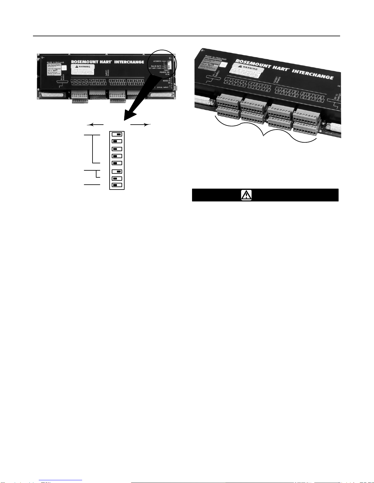
Figure 1. T
ype 2530H1 HAR
T Interchange Multiplexer
W6486/IL
Introduction
Scope of Manual
This instruction manual includes installation and main-
tenance information for the Type 2530H1 HART inter-
change multiplexer. Refer to separate manuals for
additional information on other FIELDVUEproducts
used with the multiplexer such as the Type DT4000
digital transducer, DVC5000 Series digital valve con-
trollers, HF200 Series HART filters, and the
ValveLinkSeries VL2030 software.
Only personnel qualified through training or experience
should install, operate, and maintain the Type 2530H1
HART interchange multiplexer. If there are any ques-
tions concerning these instructions contact your Fisher
Controls sales office or sales representative before
proceeding.
Description
The Type 2530H1 HART interchange multiplexer is a
HART-based multiplexer that links installed HART-
based field devices to a centralized personal computer
(PC). When used in conjunction with the ValveLink
Type VL2030 software, the multiplexer provides the
Instruction Manual
Form 5407
February 1996
Type 2530H1