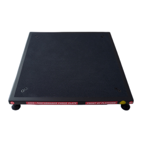
Fitness Technology 400 Series User manual

Fitness Technology
21 Bishop St.
Skye SA 5072
Australia
+61 8 8331 9229
Mob: 0418 815 400
www.fittech.com.au
Copyright: Fitness Technology, Adelaide, Australia 21st March 2005
FORCE PLATE
400 Series
Performance Force
Plate

2
FORCE PLATE 1000 Kg
Capacity
FORCE PLATE 400 Kg Capacity
Fitness Technology, 21 Bishop Street, Skye SA 5072 Australia
Tel: +61 8 8331 9229 Mob: 0418 815 400. www.fittech.com.au
Copyright: Fitness Technology, Adelaide, Australia 21st March 2005. Issue 2.00, 21st Aug 2008
Introduction:
The 1000Kg Rated Force Plate specifications
1. 795mm x 795mm x 60mm High Aluminium Framed Platform & non slip Carbon Fibre Top.
2. 4 x Load Cells complete with adjustable height feet assemblies that can adjust the height of the
Plate to approx 120mm
3. Maximum Sampling Rate –adjustable in software from 1 –600Hz on all 4 Load Cell channels
via BMS software program.
4. 400S Force Plate + BMS Linear Position Transducer (LPT )is calibrated by users on site via the
BMS software via Tools\Configure\Calibration (tab window)
5. Only Performance Force Plate on the market capable of running the BMS LPT & auto saving all
data files + outputting to Excel via the BMS software program.
6. Only Performance Force Plate on the market capable of running on our new Inner-Balance
software tracking used to measure & record all Anterior Posterior & Medial Linear movements
7. 400S Weight 20.6 Kg (45.3 lbs)
8. 1 x PCB Module operates 4 Load Cells + LPT powered via 5 V DC Computer USB Port only
9. 1 x USB 2.0 communications Cable provides 100% of power required to run the 400S from any
PC or laptop USB Port.
10. 1 x USB 2.0 Extension Cable 3 M Long provided with all 400S units
11. 1 x RJ 45 Connection (located under the Force Plate) with connection lead supplied going to 1K
Ohm Potentiometer on the BMS LPT model PT5A-150-V62-UP-1K-M6-632676A
12. The PCB shown on Page 4 is self contained in the 400S Platform Assembly.
13. To operate the 400S Platform simply installs the software onto your Hard Drive and then
connects the USB Cable plug into your Computer.
14. With the 400S no other power supply or charging of batteries is required.

3
FORCE PLATE 1000 Kg
Capacity
FORCE PLATE 400 Kg Capacity
Fitness Technology, 21 Bishop Street, Skye SA 5072 Australia
Tel: +61 8 8331 9229 Mob: 0418 815 400. www.fittech.com.au
Copyright: Fitness Technology, Adelaide, Australia 21st March 2005. Issue 2.00, 21st Aug 2008
FRONT OF PLATFORM
Load Cell Wiring
The four Load Cells connect into the XPV7 Electronics Module are colour coded on the
load cell cables at the terminal blocks for ease of wiring, they are as follows
Load Cell 1. Blue Heat - Shrink shroud as per next page
Load Cell 2. Green Heat - Shrink shroud as per next page
Load Cell 3. Red Heat - Shrink shroud as per next page
Load Cell 4. Yellow Heat - Shrink shroud as per next page
The wiring connection for each individual load cell is as follows.
Ex+ RED Terminal
Block is not
Sig + White on 400 S Plate
Sig - Green Note: Green and White wires maybe reversed.
Ex-Black
Shield (Heat shrink - wire colour may vary)
Installation:
1. Carefully unpack the platform by lifting it out the end of the transport carton.
Make sure all items are present. (Report any discrepancies immediately.)
2. Place the platform onto a flat stable surface.
3. Install each foot into the load cell holes on the four corners of the platform by
rotating the feet to the right. (right hand thread) Adjust height as show below.
4. Connect the USB communication cable as shown below by removing the plug
allowing access to the communications port. (See photos below)
5. The Platform is now ready for use.
6. Install the communications software and the processing software following the
instruction for each module
7. The XPV7 PCB Electronics Module will automatically identify any cable faults.
Should this happen make sure the communication cables are properly installed.
If communication failure continues, then replace the USB cable.
8. For any other problems contact our office for further instructions.

4
FORCE PLATE 1000 Kg
Capacity
FORCE PLATE 400 Kg Capacity
Fitness Technology, 21 Bishop Street, Skye SA 5072 Australia
Tel: +61 8 8331 9229 Mob: 0418 815 400. www.fittech.com.au
Copyright: Fitness Technology, Adelaide, Australia 21st March 2005. Issue 2.00, 21st Aug 2008
USB Cable Connections
USB Connector
Lead to RJ45
Connector to
External RJ45
Socket for LPT
cable connection
USB Connector
US8/8 Plug w lead to RJ45 Skt
Pin 2 = PT5A IK Pot V Signal
Pin 4 = USB +5V
Pin 6 = USB Gnd.
Pin 7 = MBU V Signal.

5
FORCE PLATE 1000 Kg
Capacity
FORCE PLATE 400 Kg Capacity
Fitness Technology, 21 Bishop Street, Skye SA 5072 Australia
Tel: +61 8 8331 9229 Mob: 0418 815 400. www.fittech.com.au
Copyright: Fitness Technology, Adelaide, Australia 21st March 2005. Issue 2.00, 21st Aug 2008
Installation of 4 x Platform Feet
The Platform cannot be used until the 4 x feet with M12
1.75 pitch threads are installed in each of the four corners.
They screw into the Platform with standard a right-hand
thread
Stainless Steel M12 spacer Nuts are used for levelling and
adjusting the height of the Platform. If required the M12
spacer nuts can be removed but if this is done never
thread the 4 x feet threads thru all the way - back off 5mm.
Refer Trouble shooting Note 5 on Page 7. The Platform
should also always be level when in use.
M12 Spacer
Nut

6
FORCE PLATE 1000 Kg
Capacity
FORCE PLATE 400 Kg Capacity
Fitness Technology, 21 Bishop Street, Skye SA 5072 Australia
Tel: +61 8 8331 9229 Mob: 0418 815 400. www.fittech.com.au
Copyright: Fitness Technology, Adelaide, Australia 21st March 2005. Issue 2.00, 21st Aug 2008
1 of the 4 x low profile shear beams bolted in position.
Care and Maintenance of Force Plate
To clean the Force Plate we recommend the use of standard household detergent to wipe
down the external surface area.
Note:
Do not place or allow any water to ingress into the Platform via the load cell holes or
the penetration used for the USB communication port underneath the Platform.

7
FORCE PLATE 1000 Kg
Capacity
FORCE PLATE 400 Kg Capacity
Fitness Technology, 21 Bishop Street, Skye SA 5072 Australia
Tel: +61 8 8331 9229 Mob: 0418 815 400. www.fittech.com.au
Copyright: Fitness Technology, Adelaide, Australia 21st March 2005. Issue 2.00, 21st Aug 2008
PRECAUTIONS
Before the Force Platform is used for any purpose, checks must be carried out to
ensure the safety of the individuals using the Platform. Appropriate footwear must
always be worn when using the Platform.
All operators must ensure themselves that the Platform is suitable and safe for the
application or testing purpose, by carrying out a series of tests prior to using the
system.
The Testing Officer or Force Plate Operator acknowledges the decision to use the
Force Plate and it’s suitability for the purpose rests solely with their deliberate
decision to use the device.
Warranty.
The Company warrants that the products are thoroughly examined before shipment and
agrees to make good any part that is proved to be defective due to faulty workmanship.
Defects or failures in equipment which, under proper use, appear therein and arise solely
from faulty materials or workmanship will be remedied by us free of charge provided the
equipment is returned to our Workshop within a period of twelve (12) months from date of
delivery, freight paid both ways. In the case of warranty service to equipment "on site" or at
the purchaser's premises, all traveling and accommodation costs shall be to the
purchaser's account. Damage to product including broken or damaged cabling caused by
maliciousness, negligence or through changes to electrical configuration of equipment or
voltage in excess of rating is specifically excluded from this warranty (the Proof to the
contrary being the onus of the purchaser). Where this occurs then such warranty real or
implied offered by The Company shall immediately come to an end.
The Company extends such warranties as are offered by the original manufacturer of
material. Liability under this warranty applies only to repair or replacement (at the
discretion of the Company) of the original goods supplied. The Company will not be liable
for any damages or delay (general or consequential) whether directly or indirectly caused
by the said defect, and shall not be responsible for any work done, or alterations, or
addition, made to the products by any other party.

8
FORCE PLATE 1000 Kg
Capacity
FORCE PLATE 400 Kg Capacity
Fitness Technology, 21 Bishop Street, Skye SA 5072 Australia
Tel: +61 8 8331 9229 Mob: 0418 815 400. www.fittech.com.au
Copyright: Fitness Technology, Adelaide, Australia 21st March 2005. Issue 2.00, 21st Aug 2008
Trouble shooting the 400S Force Plate
If you are unable to receive data from the 400S Force Plate there are a number of simple causes. For
technical reasons not all are detailed in this document:
1. Our system requires you have the correct and latest USB Driver. You may have an older version of
the USB driver which sometimes may not work if your PC also has a virtual COM Port driver loaded.
To fix the you can download new drivers from:
http://www.ftdichip.com/Drivers/CDM/CDM%202.04.06.exe
2. Some PCs have USB ports that are not to the full specification. If you suspect this may be an issue
then a USB hub can be added between the 400S Force Plate and your PC. When adding a USB 2.0
high quality extension lead must connect this Lead before you connect the 400S to the PC .
Then open our BMS software program with the 400S connected and then the PC will register the
presence of the 400S.
3. Are you using a USB extension lead? See 2 above. Until the trouble shooting is complete we
recommend that you disconnect any USB extension leads.
4. Now if the 400S is still not communicating with your PC we have made available a test program
which allows the XPV7 circuit board inside the 400S to be tested. When performing these tests it is
best to remove the cover plate from the underside of the platform to expose the XPV7 circuit board.
The test program is available from
http://www.innervations.com/downloads/TESTXPV7%20Install.exe
5. Fluctuating Force Plate Kg Mass values in the BMS software program - This problem normally
occurs when the 4 x M12 Feet are fully screwed thru into the 4 x Load Cells (Shear Beams).
(a) If the 4 x M12 spacer nuts are used it will not be possible to screw these 4 x Feet in too far.
(b) If these 4 spacer nuts are not used do not screw these 4 feet thru all the way back off the 4 x
Platform feet approximately 5 mm refer Page 5. Only when (a) or (b) has been done proceed to -
Step 1 Now calibrate the plate as per our web site Instructional Footage for Media Player
instructions http://www.fittech.com.au/_en/products/4_force/2_5_instructional/force_2_5.htm then
once calibrations have been completed proceed to
Step 2 - (now when step 1 has followed,) next you should be able in the in the BMS program to set
a 5 sec time test span - then in Collect & Analyse window Zero out the plate then hit then Collect
Data button put a know Mass on the Plate & it should read the correct value of the Mass.
Within 0.1 Kg is a typical acceptable Mass reading,

9
FORCE PLATE 1000 Kg
Capacity
FORCE PLATE 400 Kg Capacity
Fitness Technology, 21 Bishop Street, Skye SA 5072 Australia
Tel: +61 8 8331 9229 Mob: 0418 815 400. www.fittech.com.au
Copyright: Fitness Technology, Adelaide, Australia 21st March 2005. Issue 2.00, 21st Aug 2008
6. With the 400S connected to the PC you can now run TEST_XPV7.exe If the XPV7 circuit board
inside the 400S has initialized correctly you should see the version and serial numbers for the XPV7
in the title line of the test program. Further confirmation that the XPV7 is communicating with your
PC is the PCB System Information and PCB A/D Settings which are shown at the bottom of the
test program dialogue box. If this information is not displayed then there is either still a problem with
your PC or the XPV7 is not running. Note the “HEARTBEAT” light at the top of XPV7 should be
flashing when the test program is running. Allow a period of 15 seconds to pass before pressing the
“Start Continuous Data Transfer” Key.

10
FORCE PLATE 1000 Kg
Capacity
FORCE PLATE 400 Kg Capacity
Fitness Technology, 21 Bishop Street, Skye SA 5072 Australia
Tel: +61 8 8331 9229 Mob: 0418 815 400. www.fittech.com.au
Copyright: Fitness Technology, Adelaide, Australia 21st March 2005. Issue 2.00, 21st Aug 2008
7. To start receiving data from the 400S press the “Start Continuous Data Transfer” button. If the
equipment is operating correctly you will see “analogue” bars next to each channel and a digital
value on the right hand side. If nothing is displayed this is because the internal error checking in the
XPV7 has detected a fault and is not sending faulty data.
8. If you are not receiving data then press the “Stop Continuous Data Transfer” button.
9. So that you can determine which channel has caused the fault you must click on the “DISABLE
ERROR CHECKING” checkbox then press the “Start Continuous Data Transfer” button. Note, with
a tick the checkbox the caption changes to “DIAGNOSTIC”. Now you should see one or more
channels reading zero.

11
FORCE PLATE 1000 Kg
Capacity
FORCE PLATE 400 Kg Capacity
Fitness Technology, 21 Bishop Street, Skye SA 5072 Australia
Tel: +61 8 8331 9229 Mob: 0418 815 400. www.fittech.com.au
Copyright: Fitness Technology, Adelaide, Australia 21st March 2005. Issue 2.00, 21st Aug 2008
10. To determine the cause of the fault close the test program, disconnect the USB cable, and swap
over the pluggable terminal blocks so that the channel 1 & 2 pair is plugged into channel 3 & 4 and 3
& 4 go into 1 & 2. Now reconnect the USB cable and run the test program and repeat step 8. If the
faulty channel moves (in this case to CH #1) then there is a connection, cable, or load cell fault. If on
the other hand the fault doesn’t move then the XPV7 circuit board is faulty.
11. Next you should compare the A/D Settings at the bottom of the dialogue box, these numbers should
match exactly with what you have on screen. If these numbers do match then there is a hardware
fault on the XPV7 circuit board.
If these numbers don’t match then contact our repair centre for further instructions on resetting these
values.
Table of contents
Other Fitness Technology Fitness Equipment manuals
Popular Fitness Equipment manuals by other brands

Slendertone
Slendertone Pulse 530 instruction manual
AQUATREND
AQUATREND Water Workout Station owner's manual
CYBEX
CYBEX 19100 owner's manual
Rogers Athletic
Rogers Athletic 410343 Product information packet
HeartSine
HeartSine samaritan SAM 350P user manual
Profile Design
Profile Design Sonic Ergo 45AR user manual
