Fitness Technology 400S+ User manual

THIS MANUAL SHOULD BE READ AND UNDERSTOOD BEFORE OPERATING THIS
FORCE PLATE
Do not hesitate to contact us if you have any questions about this product
Fitness Technology
21 Bishop St.
Skye SA 5072
Australia
Postal Address: PO Box 139 Fullarton 5063
+61 418815400
Mob: 0418 815 400
Copyright: Fitness Technology, Adelaide, Australia 03 February 2020
FORCE PLATE
400S+ Performance Force
Plate Manual

1
FORCE PLATE 1000 Kg
Capacity
FORCE PLATE 400 Kg Capacity
Fitness Technology, 21 Bishop Street, Skye SA 5072 Australia
Postal Address: PO Box 139 Fullarton 5063 Tel: +61 8 8331 9229 Mob: 0418 815 400.
www.fittech.com.au E info@fittech.com.au
Copyright: Fitness Technology, Adelaide, Australia 3rd Feb 2020 Issue 1.00, 3rd Feb 2020
Page | 1
Contents
Specifications...................................................................................................................2
Load Cell Wiring...............................................................................................................3
Installation:.......................................................................................................................4
USB and PT5A position Transducer Cable Connections .................................................4
Installation of 4 x Platform Feet........................................................................................6
Levelling the 400S+ Performance Force Plate.................................................................6
Care and Maintenance of Force Plate..............................................................................7
PRECAUTIONS ...............................................................................................................7
Warranty...........................................................................................................................7
Frequently Asked Questions............................................................................................8
Q. How do you calculate your variables?......................................................................8
Q. What is the sampling period for mRFD in the BMS software? .................................8
Q. What is the sampling frequency of the BMS software?............................................8

2
FORCE PLATE 1000 Kg
Capacity
FORCE PLATE 400 Kg Capacity
Fitness Technology, 21 Bishop Street, Skye SA 5072 Australia
Postal Address: PO Box 139 Fullarton 5063 Tel: +61 8 8331 9229 Mob: 0418 815 400.
www.fittech.com.au E info@fittech.com.au
Copyright: Fitness Technology, Adelaide, Australia 3rd Feb 2020 Issue 1.00, 3rd Feb 2020
Page | 2
Specifications.
Capacity: 1000Kg Rated Force
Safety Factor: Side-load rejection ratio 500:1
Safe side-load 100 % of R.C. Maximum safe central overload 150 % of R.C.
Ultimate central overload 300 % of R.C.
Physical Size: 795mm x 795mm x 60mm
Materials: Carbon Fibre Platform with non-slip Top.
Load Cells complete with adjustable height feet assemblies that can adjust the height of the
Plate to approx 120mm
Sample Rate: Maximum Sampling Rate of 1000Hz on all channels via BMS version 2 (BMSv2) software
program.
Integration: 400S+ Performance Force Plate + BMS Linear Position Transducer (LPT) is calibrated by
users on site via the BMSv2 software via Tools\Configure\Calibration (tab window)
Unique: Only Performance Force Plate on the market with a footprint size large enough for every
users’ Centre of Mass (COM) to remain over this force plate for all testing functions for
accurate data collection all the time. It is also capable of running the BMS LPT & auto
saving all data files + outputting to Excel via the BMS software. It also measures uni-lateral &
bilateral R & L leg anterior / posterior & medio / lateral force - all done on this single 400S+
force plate!
Only Performance Force Plate on the market capable of running on our new InnerBalance
software tracking used to measure & record all anterior-posterior & mediolateral sway
movements.
Weight: 400S+, 14.5 Kg (32 lbs)
Operation: Integral PCB Module operates 4 Load Cells + Output powered via 5 V DC Computer USB
Port only. Sensor type Steel Shear Beams rating 250Kg @ 3mV/V that are genuinely rated
to sample @ 1000Hz. Simply install the software onto your Hard Drive and then connect the
USB Cable plug into your Computer. The 400S requires no other power supply or charging
of batteries is required.
PCB monitors: Sensors # 1 –4 each have a Load cell cable connector 5 terminal plug (Molex) (four in total
as shown on pages 3&4) sensors # 1&2, 3&4 may share a Load cell cable connector 10
terminal plug (Molex) (two in total as shown on page 14). These connect to 4 Load cells.
(see page 6).
Outputs: Communicates via 1 x USB 2.0 Cable that does not rely on Bluetooth or other wireless
connection to the laptop, so has NO internal batteries - annoying flat battery and recharging
issues are irrelevant!
Power: Computer USB supplies 100% of power supply to operate the 400S from any PC or laptop
USB Port. 1
Cables: 1 x USB 2.0 Extension Cable 3 M Long provided with all 400S units. This mean zero
external RF interference.
Connections: 1 x RJ 45 Connection (located under the Force Plate) with connection lead supplied going to
1K Ohm Potentiometer on the BMS LPT Model PT5A-150-V62-UP-1K-M6-632676A this
LPT is an optional plug-in connection –only used if barbell tracking data is also required to
be tracked simultaneously with the ground reaction force data (See pages 4 & 5).
3
FORCE PLATE 1000 Kg
Capacity
FORCE PLATE 400 Kg Capacity
Fitness Technology, 21 Bishop Street, Skye SA 5072 Australia
Postal Address: PO Box 139 Fullarton 5063 Tel: +61 8 8331 9229 Mob: 0418 815 400.
www.fittech.com.au E info@fittech.com.au
Copyright: Fitness Technology, Adelaide, Australia 3rd Feb 2020 Issue 1.00, 3rd Feb 2020
Page | 3
PCB: Self-contained in the 400S Platform Assembly.
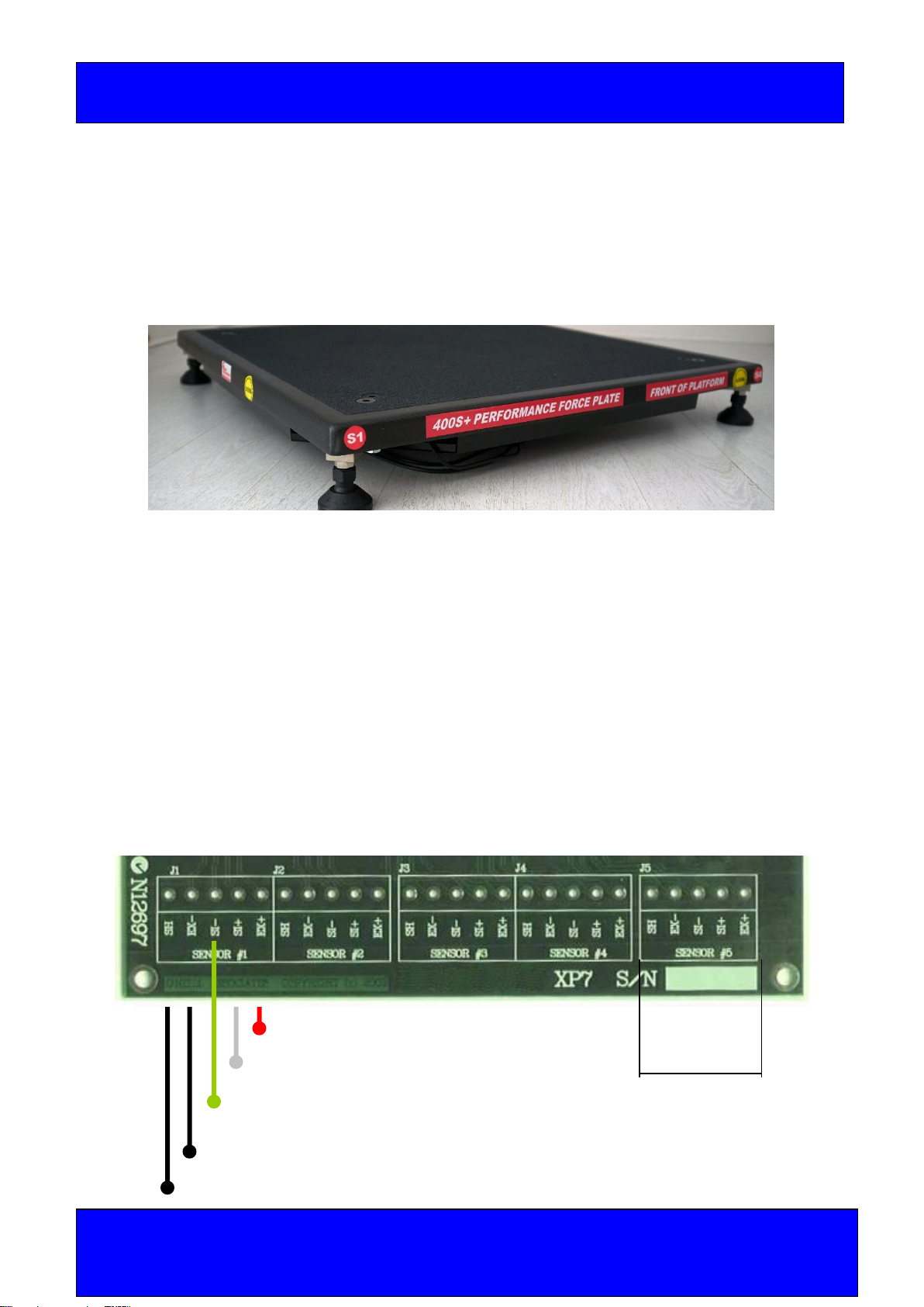
Load Cell Wiring
The four Load Cells connect into the XPV7 Electronics Module are colour coded on the
load cell cables at the terminal blocks for ease of wiring, they are as follows
Load Cell 1. Blue Heat - Shrink shroud as per next page
Load Cell 2. Green Heat - Shrink shroud as per next page
Load Cell 3. Red Heat - Shrink shroud as per next page
Load Cell 4. Yellow Heat - Shrink shroud as per next page
The wiring connection for each individual load cell is as follows.
Ex+ RED Terminal
Block is not
Sig + White on 400 S Plate
Sig - Green
Ex-Black
Shield (Heat shrink - wire colour may vary)
4
FORCE PLATE 1000 Kg
Capacity
FORCE PLATE 400 Kg Capacity
Fitness Technology, 21 Bishop Street, Skye SA 5072 Australia
Postal Address: PO Box 139 Fullarton 5063 Tel: +61 8 8331 9229 Mob: 0418 815 400.
www.fittech.com.au E info@fittech.com.au
Copyright: Fitness Technology, Adelaide, Australia 3rd Feb 2020 Issue 1.00, 3rd Feb 2020
Page | 4
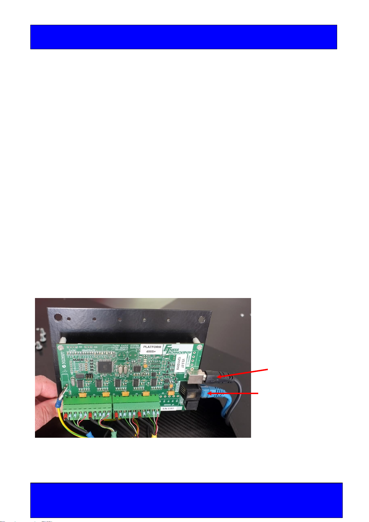
Installation:
1. Carefully unpack the platform by lifting it out the end of the transport carton. Make
sure all items are present. (Report any discrepancies immediately.)
2. Place the platform onto a flat stable surface.
3. Install each foot into the load cell holes on the four corners of the platform by
rotating the feet to the right. (right hand thread) Adjust height as show below.
4. Connect the USB communication cable as shown below by removing the plug
allowing access to the communications port. (See photos below)
5. The Platform is now ready for use.
6. Install the communications software and the processing software following the
instruction for each module
7. The XPV7 PCB Electronics Module will automatically identify any cable faults.
Should this happen make sure the communication cables are properly installed. If
communication failure continues, then replace the USB cable.
8. For any other problems contact our office for further instructions.
USB and PT5A position Transducer Cable Connections
USB Connector
US8/8 Plug Cat5e cable
Pin 2 = PT5A IK Pot V Signal
Pin 4 = USB +5V
Pin 6 = USB Gnd.
Pin 7 = MBU V Signal.

5
FORCE PLATE 1000 Kg
Capacity
FORCE PLATE 400 Kg Capacity
Fitness Technology, 21 Bishop Street, Skye SA 5072 Australia
Postal Address: PO Box 139 Fullarton 5063 Tel: +61 8 8331 9229 Mob: 0418 815 400.
www.fittech.com.au E info@fittech.com.au
Copyright: Fitness Technology, Adelaide, Australia 3rd Feb 2020 Issue 1.00, 3rd Feb 2020
Page | 5
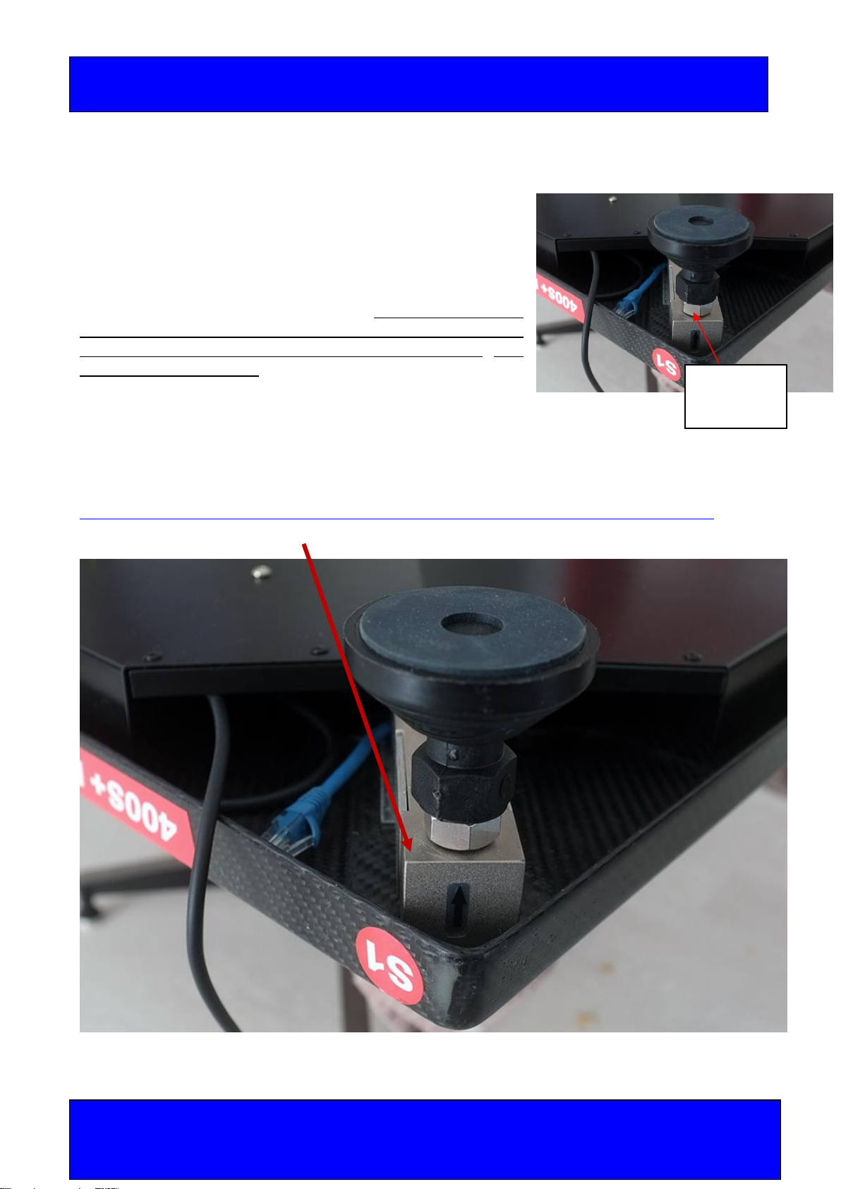
In the image above you can see the USB connector for the Force plate and the cat5e
connector for the LPT. Both are tucked back in under the rear cover for shipping.
See below for an example of the PT5A position transducer connected to the 400S+
Performance force plate.
USB Connector
Cat5e Lead connects
to RJ45 Socket on the
LPT cable connection
6
FORCE PLATE 1000 Kg
Capacity
FORCE PLATE 400 Kg Capacity
Fitness Technology, 21 Bishop Street, Skye SA 5072 Australia
Postal Address: PO Box 139 Fullarton 5063 Tel: +61 8 8331 9229 Mob: 0418 815 400.
www.fittech.com.au E info@fittech.com.au
Copyright: Fitness Technology, Adelaide, Australia 3rd Feb 2020 Issue 1.00, 3rd Feb 2020
Page | 6
Installation of 4 x Platform Feet
The Platform cannot be used until the 4 x feet with M12 1.75
pitch threads are installed in each of the four corners. They
screw into the Platform with standard a right-hand thread.
Stainless Steel M12 spacer Nuts are used for levelling and
adjusting the height of the Platform. If required the M12
spacer nuts can be removed but if this is done never thread
the 4 x feet threads thru all the way - back off 5mm. See
page 11 for more detail.
Levelling the 400S+ Performance Force Plate
The Platform should also always be level when in use.
How to level the 400S+ performance force plate using the XPV7 diagnostic software.
1 of the 4 x low profile shear beams bolted in position.
M12 Spacer
Nut

7
FORCE PLATE 1000 Kg
Capacity
FORCE PLATE 400 Kg Capacity
Fitness Technology, 21 Bishop Street, Skye SA 5072 Australia
Postal Address: PO Box 139 Fullarton 5063 Tel: +61 8 8331 9229 Mob: 0418 815 400.
www.fittech.com.au E info@fittech.com.au
Copyright: Fitness Technology, Adelaide, Australia 3rd Feb 2020 Issue 1.00, 3rd Feb 2020
Page | 7
Care and Maintenance of Force Plate
To clean the Force Plate, we recommend the use of standard household detergent to wipe
down the external surface area.
Note:
Do not place or allow any water to ingress into the Platform via the load cell holes or the
penetration used for the USB communication port underneath the Platform.
PRECAUTIONS
Before the Force Platform is used for any purpose, checks must be carried out to ensure
the safety of the individuals using the Platform. Appropriate footwear must always be worn
when using the Platform.
All operators must ensure themselves that the Platform is suitable and safe for the
application or testing purpose, by carrying out a series of tests prior to using the system.
The Testing Officer or Force Plate Operator acknowledges the decision to use the Force
Plate and it’s suitability for the purpose rests solely with their deliberate decision to use the
device.
Warranty.
The Company warrants that the products are thoroughly examined before shipment and
agrees to make good any part that is proved to be defective due to faulty workmanship.
Defects or failures in equipment which, under proper use, appear therein and arise solely
from faulty materials or workmanship will be remedied by us free of charge provided the
equipment is returned to our Workshop within a period of twelve (12) months from date of
delivery, freight paid both ways. In the case of warranty service to equipment "on site" or at
the purchaser's premises, all traveling and accommodation costs shall be to the
purchaser's account. Damage to product including broken or damaged cabling caused by
maliciousness, negligence or through changes to electrical configuration of equipment or
voltage in excess of rating is specifically excluded from this warranty (the Proof to the
contrary being the onus of the purchaser). Where this occurs then such warranty real or
implied offered by The Company, shall immediately come to an end, The Company
extends such warranties as are offered by the original manufacturer of material. Liability
under this warranty applies only to repair or replacement (at the discretion of the
Company) of the original goods supplied. The Company will not be liable for any damages
or delay (general or consequential) whether directly or indirectly caused by the said defect,
and shall not be responsible for any work done, or alterations, or addition, made to the
products by any other party.
NO VERBAL ARRANGEMENTS: If the purchaser accepts this quotation it is
acknowledged that any variations to the terms and conditions herein defined must be

8
FORCE PLATE 1000 Kg
Capacity
FORCE PLATE 400 Kg Capacity
Fitness Technology, 21 Bishop Street, Skye SA 5072 Australia
Postal Address: PO Box 139 Fullarton 5063 Tel: +61 8 8331 9229 Mob: 0418 815 400.
www.fittech.com.au E info@fittech.com.au
Copyright: Fitness Technology, Adelaide, Australia 3rd Feb 2020 Issue 1.00, 3rd Feb 2020
Page | 8
given in writing by Fitness Technology and that no reliance will be placed upon oral
representation.
APPLICABLE LAW: Shall be the Law of the State of South Australia, and no variations to
these conditions can be agreed to unless such agreement is in writing and signed by The
Company.
Frequently Asked Questions
Q. How do you calculate your variables?
A. We use standard biomechanical analysis to derive the additional data sets and
summary parameters.
1. Vertical ground reaction force measured directly using the force plate
2. Force data is then integrated over time to derive the velocity time data set.
3. Velocity data is then integrated over time to derive the displacement time data set.
4. Power is calculated as instantaneous velocity multiplied by instantaneous force that
each time point.
5. Maximum and minimum as well as average summary variables are being calculated
for each data set.
6. Additional summary variables such as impulse over defined time periods, time to
various peaks, rate of force development and time periods of various phases are
calculated using standard biomechanical methods.
Q. What is the sampling period for mRFD in the BMS software?
A. mRFD is calculated as the greatest increase in force over a 30ms time epoch for the
selected section of the data –that is the period of data displayed in the graph.
Q. What is the sampling frequency of the BMS software?
A. The 400S+ performance force plate has a sampling frequency of 1000Hz. Your XPV7
interface sample frequency can be determined by running the XPV7 diagnostic software
and looking at the equipment type highlighted in the image below. The XPV7 diagnostic
software can be downloaded here.

9
FORCE PLATE 1000 Kg
Capacity
FORCE PLATE 400 Kg Capacity
Fitness Technology, 21 Bishop Street, Skye SA 5072 Australia
Postal Address: PO Box 139 Fullarton 5063 Tel: +61 8 8331 9229 Mob: 0418 815 400.
www.fittech.com.au E info@fittech.com.au
Copyright: Fitness Technology, Adelaide, Australia 3rd Feb 2020 Issue 1.00, 3rd Feb 2020
Page | 9
Table of contents
Other Fitness Technology Fitness Equipment manuals

Popular Fitness Equipment manuals by other brands


G-FITNESS
G-FITNESS AIR ROWER user manual

CAPITAL SPORTS
CAPITAL SPORTS Dominate Edition 10028796 manual

Martin System
Martin System TT4FK user guide

CIRCLE FITNESS
CIRCLE FITNESS E7 owner's manual

G-FITNESS
G-FITNESS TZ-6017 user manual

Accelerated Care Plus
Accelerated Care Plus OMNISTIM FX2 CYCLE/WALK user manual


