FitWork Walkstation A7TG660606H User manual

Installation Instructions
FitWork™Walkstation Installation Instructions
www.details-worktools.com
005720D Rev D
Page 1 of 20
©2007 Office Details Inc. All rights reserved. Printed in U.S.A. 2/09
P.O. Box 1967 / CD-5E / Grand Rapids, MI 49501-1967 / www.details-worktools.com
#2 Phillips Bit
with Extension
Tools Required:
Series 7 AdjusTables
FitWork™Walkstation
7/16"
10mm
Socket Wrench
A7TG660606H A7TR663232H
A7TG660632H A7TR383030H
A7TG663206H A7TR782929H

1
2
3
4
Installation Instructions
005720D Rev D
Page 2 of 20
Series 7 AdjusTables
FitWork™Walkstation
STRETCHER
ELECTRICAL
PIGTAIL
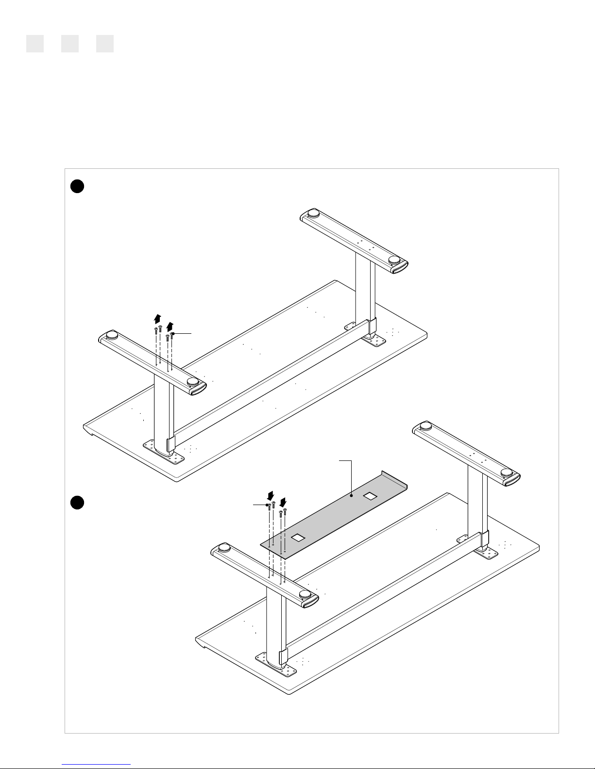
Unpack and sort all components.
Position top upside down on the assembly surface.
Layout the left and right lift columns, lift the stretcher into each
dovetail, connect loosely. (Left and right is determined when the
table is standing on the base and is viewed from the front.)
Once each lift column has been engaged, lightly tap each connection
point with a rubber mallet 1/8-1/4 inch at a time, until completely
seated. Do not completely install one lift column at a time...they
must be installed incrementally.
Notes:
A clean, abrasion
free surface will be
necessary for table
assembly.
Worksurface Assembly
NOTCH
RIGHT COLUMN
LEFT COLUMN
STRETCHER
FLUSH
DOVETAIL
DOVETAIL
COLUMN STRETCHER
TOP VIEW
For each lift column, fold the electrical 'pig-tail' towards the center of
the surface. Secure in the notch provided in each lift column.
5
www.details-worktools.com
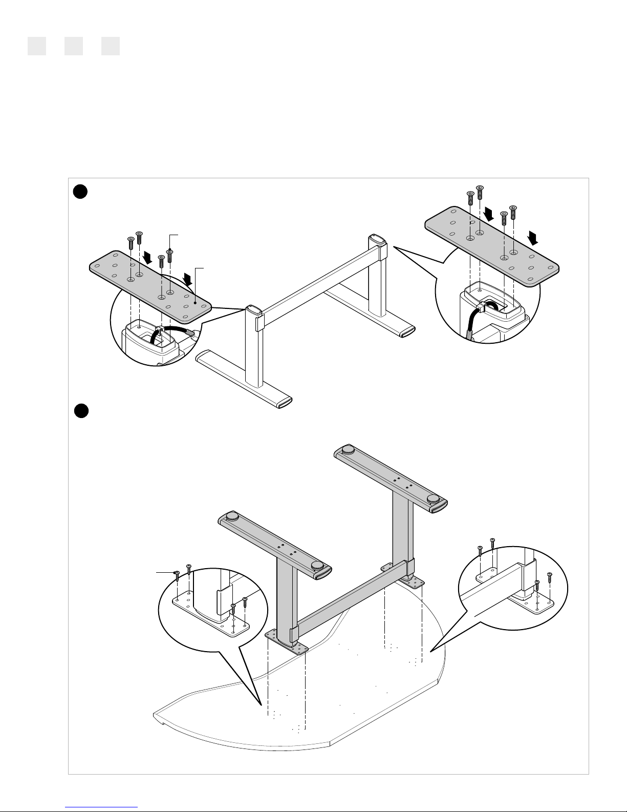
With the top still upside down on the
floor, turn the base over (flipping is a 2
person job) and align the attachment
plates to the pre-drilled holes in the
top. Loosely install one phillips head
fastener in each of the 4 corners of the
attachment plate. Don't install all
fasteners until the unit has been
operated through one cycle (Step 13).
Installation Instructions
005720D Rev D
Page 3 of 20
Series 7 AdjusTables
FitWork™Walkstation
www.details-worktools.com
PHILLIPS
HEAD
SCREW
4mm HEX HEAD FASTENERS
ATTACHMENT PLATE
Locate and install each attachment plate using 4mm hex head
fasteners provided. Tighten securely.
6
7
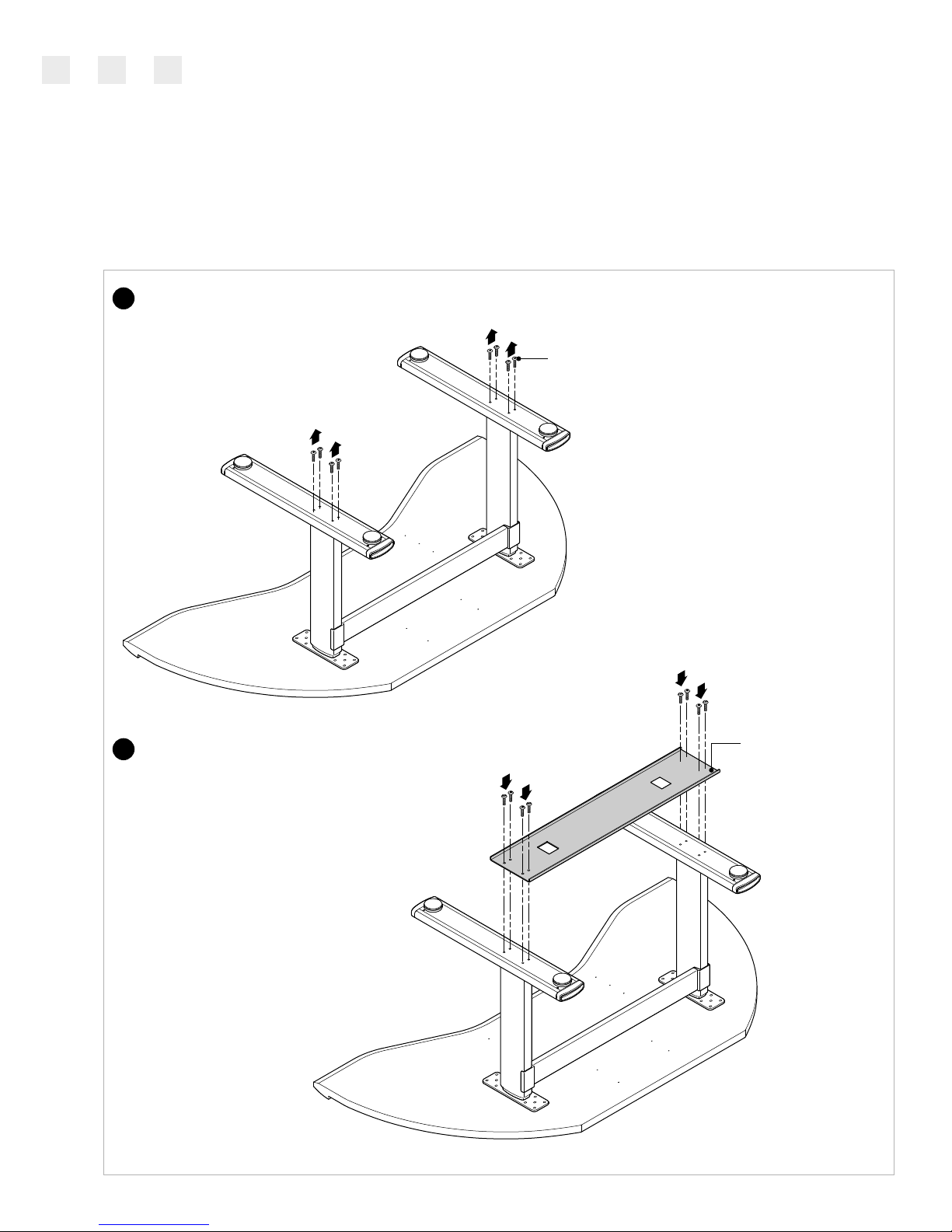
Remove four (4) screws on each foot.
Lower treadmill receiver onto legs and
attach using four (4) screws on each
leg.
Installation Instructions
005720D Rev D
Page 4 of 20
Series 7 AdjusTables
FitWork™Walkstation
www.details-worktools.com
TREADMILL
RECEIVER
SCREW
8
9

Install control box in the
predetermined location, using
pre-drilled holes.
Installation Instructions
005720D Rev D
Page 5 of 20
Series 7 AdjusTables
FitWork™Walkstation
www.details-worktools.com
10
CONTROL BOX
a
e
d
c
b
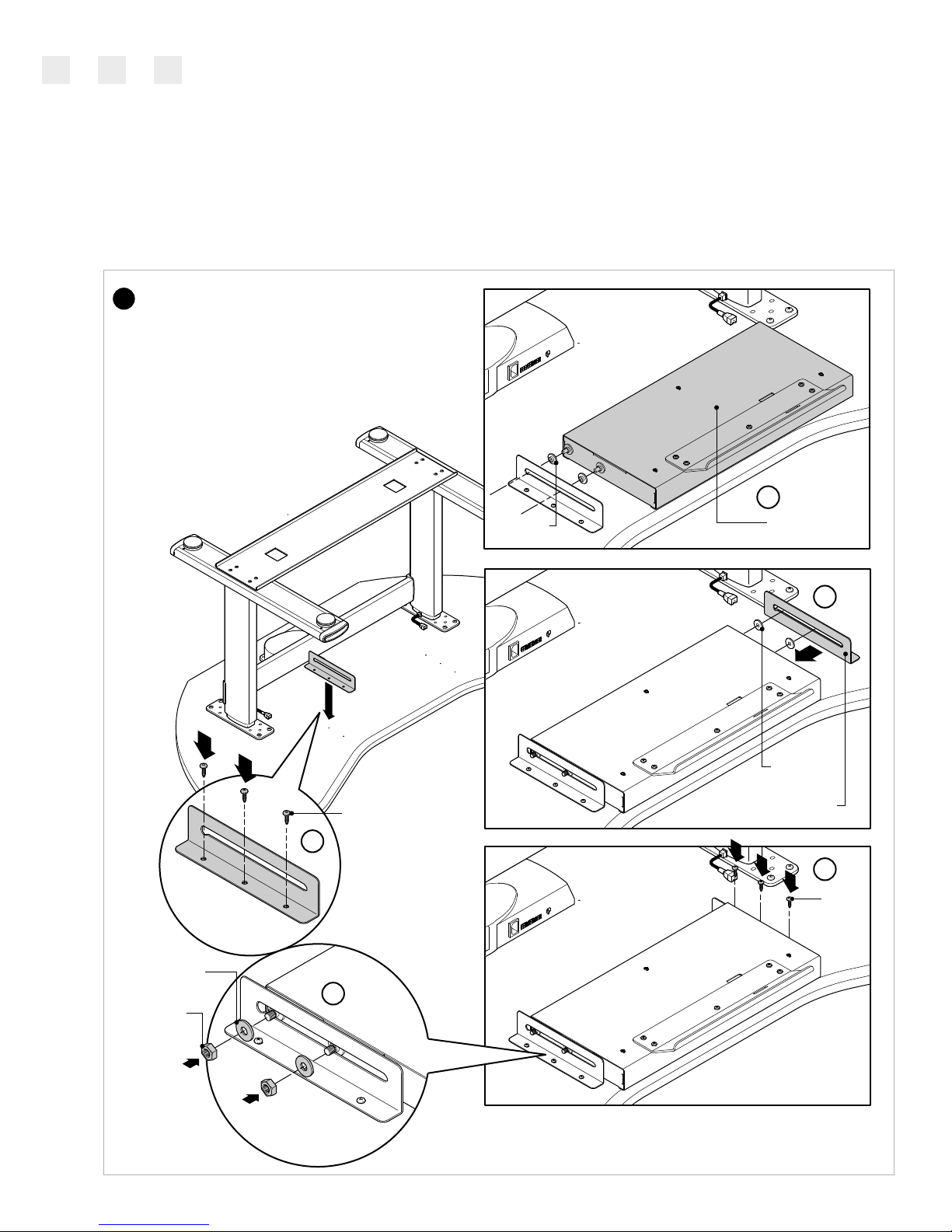
Locate pilot holes and place one (1) console
mounting bracket assembly onto underside of
worksurface. Attach bracket using three (3) screws
(a). Slide console next to bracket and make sure
threaded studs are inserted into slot (b). Slide
other console mounting bracket next to
console making sure holes in bracket are
lined up with pilot holes on worksurface (c).
Secure bracket to worksurface using three (3)
screws (d). Secure brackets to each side
of console using two (2) nuts and two (2)
flat washers (e).
Installation Instructions
005720D Rev D
Page 6 of 20
Series 7 AdjusTables
FitWork™Walkstation
www.details-worktools.com
11
SHOULDER
WASHER
CONSOLE
SHOULDER
WASHER
CONSOLE MOUNTING
BRACKET ASSEMBLY
SCREW
SCREW
FLAT WASHER
NUT

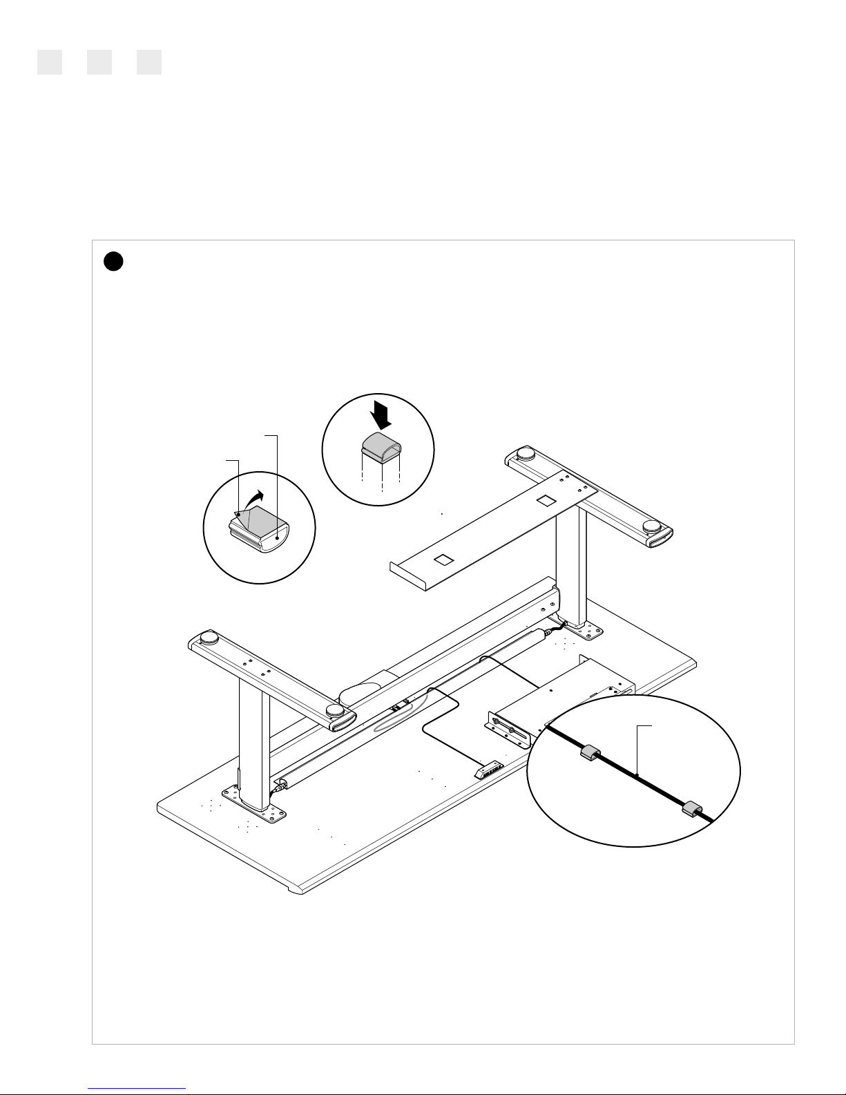
Install the wire management
cableway on the underside of
the worksurface about 5" in
front of the control box.
Connect the cables to each lift column and connect the
terminal end to the control box. Route these cables in the
wire management cableway provided. Refer to the Wiring
Guide for more information.
For best wire management, connect lift columns to the
closest port on the control box.
Installation Instructions
005720D Rev D
Page 7 of 20
Series 7 AdjusTables
FitWork™Walkstation
www.details-worktools.com
WIRE MANAGER
13
12
5"
PORT #1
PORT #2
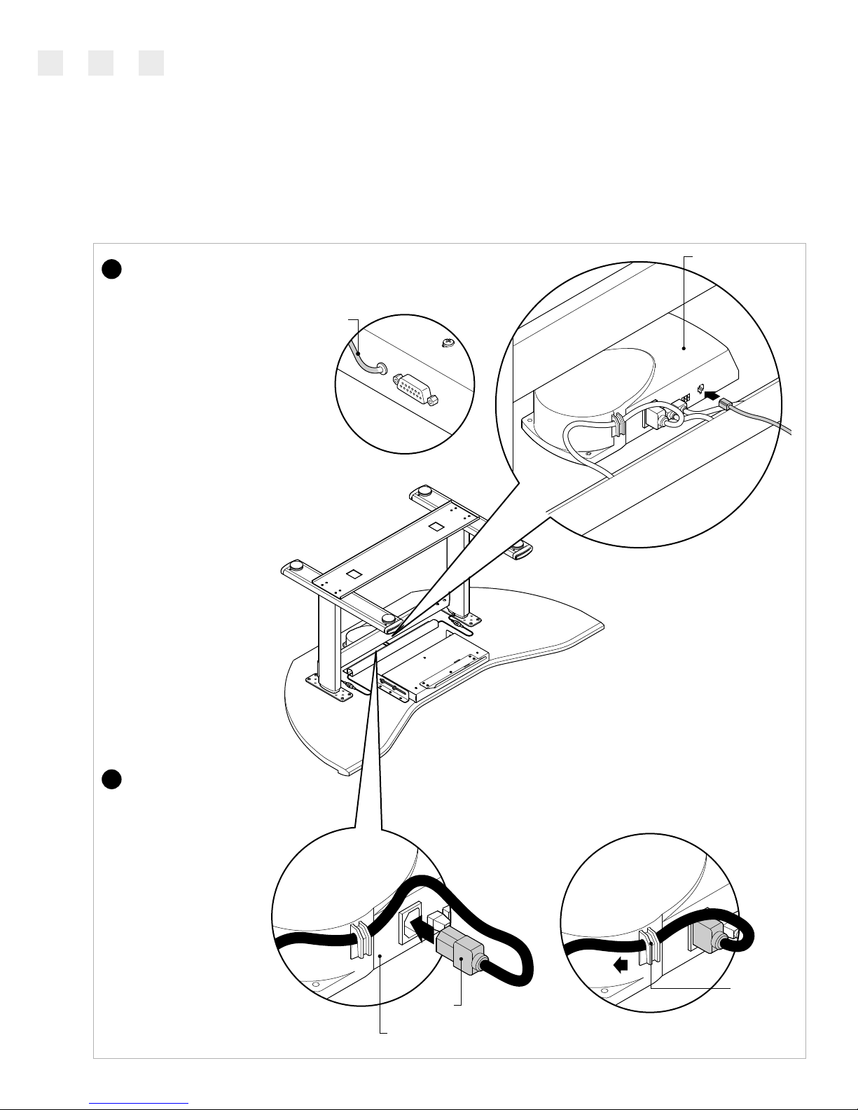
Install the cable located on the back of the console
into the control box as shown. Store extra cable
length into wire manager.
Install the plug into the control box. Secure the cord to the
control box using the molded-in clip. Plug the cord into an
outlet and check for binding, then lower to the bottom and
unplug unit. Install the remaining fasteners in each of the
remaining holes and tighten ALL screws securely.
Do not over tighten.
Installation Instructions
005720D Rev D
Page 8 of 20
Series 7 AdjusTables
FitWork™Walkstation
www.details-worktools.com
CABLE FROM CONSOLE
CONTROL BOX
14
15
PLUG
CONTROL BOX
MOLDED CLIP

Carefully turn the table over (2 person operation).
NOTE: Do NOT use either lift column as a brace
when turning the table over as this may cause
binding. The top must be lifted free, rotated and
set down carefully.
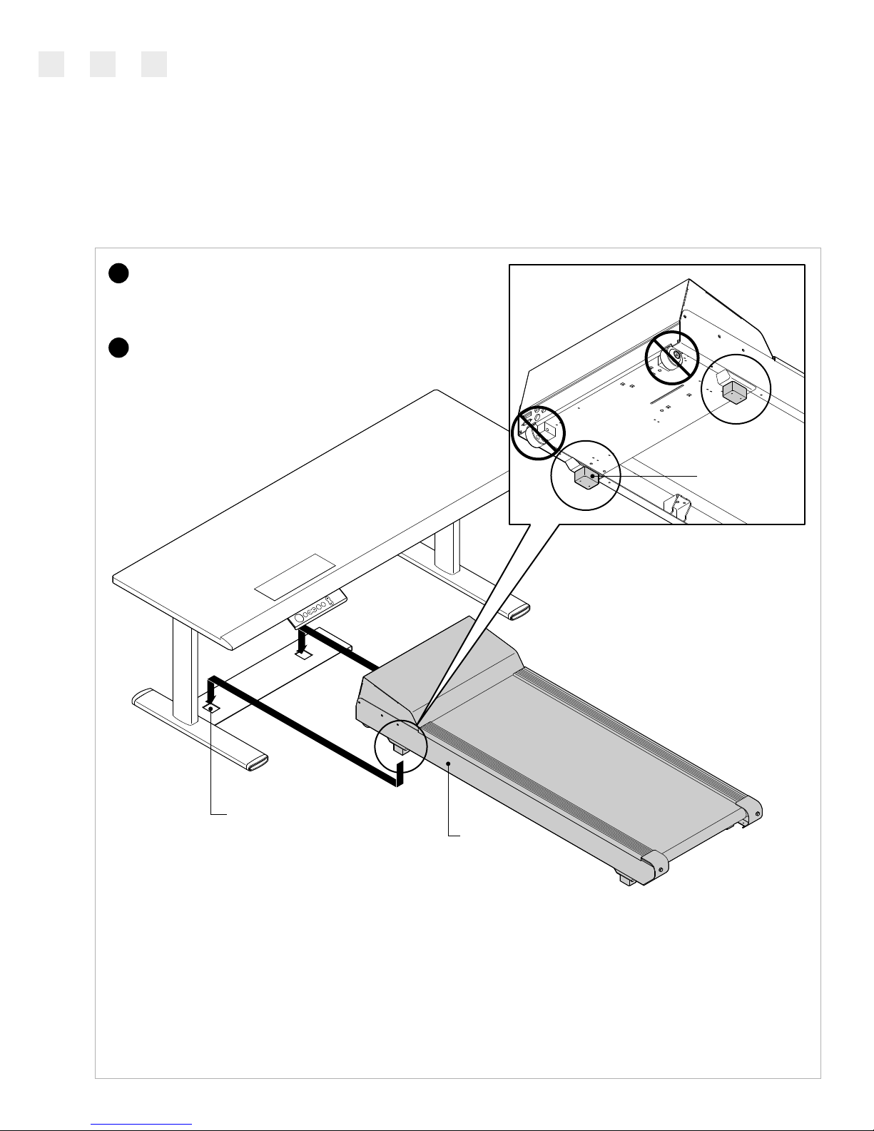
Install treadmill. Align treadmill with unit as shown. Make
sure the two (2) treadmill feet are inserted into the two (2)
holes in the treadmill receiver.
NOTE: The holes in the treadmill
receiver are for the treadmill feet,
not the treadmill wheels.
Installation Instructions
005720D Rev D
Page 9 of 20
Series 7 AdjusTables
FitWork™Walkstation
www.details-worktools.com
HOLE IN TREADMILL
RECEIVER
17
16
TREADMILL
TREADMILL FOOT

a
b
c
Locate back left of treadmill and plug in signal cable as indicated
(a). Locate back center of console and plug in other end of
signal cable as indicated (b). Plug the cord of the table and the
treadmill into an outlet. Make sure treadmill is turned on (c).
NOTE for (a) & (b): Be sure to secure signal cable to the console
and treadmill with the screws integral to the cable connector.
This will ensure a good connection.
Installation Instructions
005720D Rev D
Page 10 of 20
Series 7 AdjusTables
FitWork™Walkstation
www.details-worktools.com
REAR OF
TREADMILL
18
SIGNAL CABLE
CONSOLE
View from Underneath
Worksurface
SIGNAL CABLE
CONSOLE

Before use, the table must be completely leveled, front-to back and side-to-side.
Coordinating the Lifting Columns
Prior to initial use of the height adjustment function you must "synchronize the system".
The installers who setup the worksurface may have already done so, but it's OK to repeat this function.
Synchronize the System
• Press the Down arrow until the worksurface comes to a stop at the lowest position.
• Release the Down arrow.
• Press and hold the down arrow for approximately 5 seconds while the table
synchronizes itself. The surface will lower itself approximately 5mm, then rise
approximately 5mm and finally settle back to its lowest position.
NOTE: It may be necessary to repeat the synchronization process more than once.
After performing this function, the movement of all lift columns connected is coordinated.
In the unlikely event that an error occurs, reset the control unit by pressing the Up and
Down buttons at the same time for 5 seconds. Then repeat the synchronizing sequence
as previously outlined above.
Raise or lower desk height
by pressing buttons on the
console.
NOTE: Guidelines on Moving the Table, see page 19.
For Wiring Guide, see page 20.
Connect safety key to magnetic
attachment area on
front of keypad.
Pull console forward.
Installation Instructions
005720D Rev D
Page 11 of 20
Series 7 AdjusTables
FitWork™Walkstation
www.details-worktools.com
19 20
21
22
GLIDE

Repeat steps 1 through 6 on pages 2 and 3.
With the top still upside down on the floor, turn the
base over (flipping is a 2 person job) and align the
attachment plates to the pre-drilled holes in the top.
Loosely install one phillips head fastener in each of
the 4 corners of the attachment plate. Don't install
all fasteners until the unit has been operated
through one cycle (Step 18).
Installation Instructions
005720D Rev D
Page 12 of 20
Series 7 AdjusTables
www.details-worktools.com
PHILLIPS
HEAD
SCREW
1
2
Sit-to-Walkstation Worksurface Assembly
If you want the treadmill placed on
the right side, use these pilot holes
for attaching legs.
If you want the treadmill placed on
the left side, use these pilot holes
for attaching legs.
Underside of Worksurface
REAR OF WORKSURFACE
FRONT OF WORKSURFACE
FitWork™Sit-to-Walkstation
Remove four (4) screws on one foot on the side
of the table where the treadmill will be installed.
(left side installation shown).
Lower treadmill receiver onto leg and
attach using four (4) screws.
Installation Instructions
005720D Rev D
Page 13 of 20
Series 7 AdjusTables
www.details-worktools.com
SIT-WALK
TREADMILL RECEIVER
3
4
SCREW
SCREW
FitWork™Sit-to-Walkstation

Repeat steps 10 thru 13 on pages 5, 6 & 7.
Install the controller to the underside of the worksurface
towards the middle of the worksurface as shown.
Installation Instructions
005720D Rev D
Page 14 of 20
Series 7 AdjusTables
www.details-worktools.com
5
6
FitWork™Sit-to-Walkstation
Install the wire keepers for the control wire. Peel off paper
backing and stick to worksurface. Place wire into each wire
keeper.
Repeat steps 14 & 15 on page 8.
Installation Instructions
005720D Rev D
Page 15 of 20
Series 7 AdjusTables
www.details-worktools.com
CONTROL
WIRE
WIRE KEEPER
7
PAPER BACKING
FitWork™Sit-to-Walkstation

Installation Instructions
005720D Rev D
Page 16 of 20
Series 7 AdjusTables
FitWork™Sit-to-Walkstation
www.details-worktools.com
8
Carefully turn the table over (2 person operation).
NOTE: Do NOT use either lift column as a brace
when turning the table over as this may cause
binding. The top must be lifted free, rotated and
set down carefully.
Install treadmill. Align treadmill with unit as shown. Make
sure the two (2) treadmill feet are inserted into the two (2)
holes in the treadmill receiver.
NOTE: The holes in the treadmill receiver are for
the treadmill feet, not the treadmill wheels.
Plug in cable from back of treadmill to back of console as
shown on step 18 on page 10. Also, plug cord of the table
and the treadmill into an outlet & make sure the treadmill
is on as shown on step 18 on page 10.
Installation Instructions
005720D Rev D
Page 17 of 20
Series 7 AdjusTables
www.details-worktools.com
FitWork™Sit-to-Walkstation
RECEIVER
9
10
HOLE IN TREADMILL
TREADMILL FOOT
TREADMILL

Installation Instructions
005720D Rev D
Page 18 of 20
Series 7 AdjusTables
www.details-worktools.com
FitWork™Sit-to-Walkstation
Pull console forward.
11
Connect safety key to magnetic
attachment area on
front of keypad.
12
GLIDE
Before use, the table must be completely leveled, front-to back and side-to-side.
Coordinating the Lifting Columns
Prior to initial use of the height adjustment function you must "synchronize the system".
The installers who setup the worksurface may have already done so, but it's OK to repeat this function.
Synchronize the System
• Press the Down arrow until the worksurface comes to a stop at the lowest position.
• Release the Down arrow.
• Press and hold the down arrow for approximately 5 seconds while the table
synchronizes itself. The surface will lower itself approximately 5mm, then rise
approximately 5mm and finally settle back to its lowest position.
NOTE: It may be necessary to repeat the synchronization process more than once.
After performing this function, the movement of all lift columns connected is coordinated.
In the unlikely event that an error occurs, reset the control unit by pressing the Up and
Down buttons at the same time for 5 seconds. Then repeat the synchronizing sequence
as previously outlined above.
13
14
Raise or lower desk height
by pressing buttons on the
console.
NOTE: Guidelines on Moving the Table, see page 19.
For Wiring Guide, see page 20.

Installation Instructions
005720D Rev D
Page 19 of 20
Series 7 AdjusTables
www.details-worktools.com
FitWork™Sit-to-Walkstation
Guidelines on Moving the Table
When possible, the tables should be moved in a horizontal (flat) position.
If the table must be moved vertically (i.e. standing on a pallet), care must be taken to ensure no side pressure
is placed on any of the legs as it is tipped into position, during transport, and when tipped off the pallet at the
new location.
Before in use in the location, the table must again be completely leveled side-to-side and front-to-back. Failure
to do so may cause binding of the leg(s) and failure to operate properly.
After moving, the legs must be re-synchronized by holding 'down' arrow on the controller while the legs seek
to level themselves.
1
2
3
4
STRETCHER
FOOT
GLIDES
CONTROL BOX ATTACHMENT
PLATE

When connecting cables as stated in Step 13, use this guide
as a reference.
Connect the cables from the Lift Columns to the cables
provided. The other end should be connected to the Control
Box. Repeat this for each leg.
Connect the end of the Controller cable into the Control Box.
Follow Steps 13, 14, 15 & 18 to complete the wiring installation.
Once you have completed the wiring, use the Wire
Management Cableways to hold all the cables and minimize
possible entanglements.
NOTE: Cableways and vertical wire management solutions are
also available from Details. Contact us for more information.
Installation Instructions
005720D Rev D
Page 20 of 20
Series 7 AdjusTables
www.details-worktools.com
FitWork™Sit-to-Walkstation
Wiring Guide
1
2
3
4
5
ATTACHMENT
PLATE
FOOT
GLIDES
CONTROL BOX
• Never attach wires to the
legs or stretcher in any way.
CONTROL
RIGHT LIFT
COLUMN
LEFT LIFT
COLUMN
This manual suits for next models
5
Table of contents
Other FitWork Treadmill manuals


