Flachmann und Heggelbacher Docklight V2.2 User manual

Docklight V2.2 User Manual 07/2016
Copyright 2016 Flachmann und Heggelbacher GbR

2
Docklight V2.2 User Manual 07/2016 Copyright 2016 Flachmann und Heggelbacher GbR
Table of Contents
1. Copyright 5
2. Introduction 7
2.1 Docklight - Overview ..................................................................................................... 8
2.2 Typical Applications ....................................................................................................... 9
2.3 System Requirements .................................................................................................. 10
3. User Interface 11
3.1 Main Window ............................................................................................................... 12
3.2 Clipboard - Cut, Copy & Paste ..................................................................................... 13
3.3 Notepad ........................................................................................................................ 13
4. Features and Functions 14
4.1 How Serial Data Is Processed and Displayed ............................................................. 15
4.2 Editing and Managing Sequences .............................................................................. 15
5. Working with Docklight 17
5.1 Testing a Serial Device or a Protocol Implementation ............................................. 18
5.2 Simulating a Serial Device ........................................................................................... 19
5.3 Monitoring Serial Communications Between Two Devices ..................................... 21
5.4 Catching a Specific Sequence and Taking a Snapshot of the Communication........ 23
5.5 Logging and Analyzing a Test ...................................................................................... 23
5.6 Checking for Sequences With Random Characters (Receive Sequence
Wildcards) ..................................................................................................................... 24
5.7 Saving and Loading Your Project Data ...................................................................... 26
6. Working with Docklight (Advanced) 28
6.1 Sending Commands With Parameters (Send Sequence Wildcards) ........................ 29
6.2 How to Increase the Processing Speed and Avoid "Input Buffer Overflow"
Messages ....................................................................................................................... 30
6.3 How to Obtain Best Timing Accuracy ........................................................................ 31
6.4 Calculating and Validating Checksums ....................................................................... 31
6.5 Controlling and Monitoring RS232 Handshake Signals ............................................ 33
6.6 Creating and Detecting Inter-Character Delays ......................................................... 37
6.7 Setting and Detecting a "Break" State ...................................................................... 39
7. Examples and Tutorials 41
7.1 Testing a Modem - Sample Project: ModemDiagnostics.ptp ................................... 42
7.2 Reacting to a Receive Sequence - Sample Project: PingPong.ptp ........................... 43
7.3 MODBUS RTU With CRC checksum - Sample Project: ModbusRtuCrc.ptp .............. 44

3
Docklight V2.2 User Manual 07/2016 Copyright 2016 Flachmann und Heggelbacher GbR
Table of Contents
8. Reference 46
8.1 Menu and Toolbar ....................................................................................................... 47
8.2 Dialog: Edit Send Sequence ........................................................................................ 48
8.3 Dialog: Edit Receive Sequence .................................................................................... 49
8.4 Dialog: Start Logging / Create Log File(s) ................................................................... 50
8.5 Dialog: Find Sequence ................................................................................................. 51
8.6 Dialog: Send Sequence Parameter ............................................................................. 51
8.7 Dialog: Project Settings - Communication ................................................................. 52
8.8 Dialog: Project Settings - Flow Control ...................................................................... 54
8.9 Dialog: Project Settings - Communication Filter ....................................................... 54
8.10 Dialog: Options ............................................................................................................. 55
8.11 Dialog: Customize HTML Output ................................................................................. 56
8.12 Dialog: Expert Options ................................................................................................. 58
8.13 Keyboard Console ........................................................................................................ 59
8.14 Checksum Specification ............................................................................................... 59
9. Support 62
9.1 Web Support and Troubleshooting ........................................................................... 63
9.2 E-Mail Support ............................................................................................................. 63
10. Appendix 64
10.1 ASCII Character Set Tables ........................................................................................... 65
10.2 Hot Keys ........................................................................................................................ 67
10.3 RS232 Connectors / Pinout ......................................................................................... 68
10.4 Standard RS232 Cables ................................................................................................ 70
10.5 Docklight Monitoring Cable RS232 SUB D9 ............................................................... 73
10.6 Docklight Tap ............................................................................................................... 74
10.7 Docklight Tap Pro / Tap 485 ....................................................................................... 75
11. Glossary / Terms Used 77
11.1 Action ............................................................................................................................ 78
11.2 Break ............................................................................................................................. 78
11.3 Character ...................................................................................................................... 78
11.4 CRC ................................................................................................................................. 78
11.5 DCE ................................................................................................................................ 79
11.6 DTE ................................................................................................................................ 79
11.7 Flow Control ................................................................................................................. 79
11.8 LIN ................................................................................................................................. 79

4
Docklight V2.2 User Manual 07/2016 Copyright 2016 Flachmann und Heggelbacher GbR
Table of Contents
11.9 MODBUS ....................................................................................................................... 79
11.10 Multidrop Bus (MDB) ................................................................................................... 80
11.11 Receive Sequence ........................................................................................................ 80
11.12 RS232 ............................................................................................................................. 80
11.13 RS422 ............................................................................................................................. 81
11.14 RS485 ............................................................................................................................. 81
11.15 Send Sequence ............................................................................................................. 81
11.16 Sequence ...................................................................................................................... 82
11.17 Sequence Index ............................................................................................................ 82
11.18 Serial Device Server ..................................................................................................... 82
11.19 Snapshot ....................................................................................................................... 82
11.20 Trigger ........................................................................................................................... 82
11.21 UART .............................................................................................................................. 83
11.22 Virtual Null Modem ..................................................................................................... 83
11.23 Wildcard ....................................................................................................................... 83
0
Index

Copyright

6
Docklight V2.2 User Manual 07/2016 Copyright 2016 Flachmann und Heggelbacher GbR
Copyright
1 Copyright
Copyright 2016 Flachmann und Heggelbacher GbR
All rights reserved. No parts of this work may be reproduced in any form or by any
means - graphic, electronic, or mechanical, including photocopying, recording, taping, or
information storage and retrieval systems - without the written permission of the
publisher.
Trademarks
Products that are referred to in this document may be either trademarks and/or
registered trademarks of the respective owners. The publisher and the author make no
claim to these trademarks.
Microsoft and Windows are either registered trademarks or trademarks of Microsoft
Corporation in the United States and/or other countries.
Disclaimer
While every precaution has been taken in the preparation of this document, the publisher
and the author assume no responsibility for errors or omissions, or for damages resulting
from the use of information contained in this document or from the use of programs and
source code that may accompany it. In no event shall the publisher and the author be
liable for any loss of profit or any other commercial damage caused or alleged to have
been caused directly or indirectly by this document.
Contact
E-Mail Support: docklight@fuh-edv.de
Flachmann & Heggelbacher
Waldkirchbogen 27
D-82061 Neuried
Germany
http://www.fuh-edv.de

Introduction

8
Docklight V2.2 User Manual 07/2016 Copyright 2016 Flachmann und Heggelbacher GbR
Introduction
2 Introduction
2.1 Docklight - Overview
Docklight is a testing, analysis and simulation tool for serial communication protocols
(RS232, RS485/422 and others). It allows you to monitor communications between two
serial devices or to test the serial communication of a single device. Docklight is easy to
use and works on almost any standard PC running Windows 10, Windows 8, Windows
7, Windows Vista or Windows XP.
Docklight's key functions include
·simulating serial protocols - Docklight can send out user-defined sequences
according to the protocol used and it can react to incoming sequences. This makes it
possible to simulate the behavior of a serial communication device, which is
particularly useful for generating test conditions that are hard to reproduce with the
original device (e.g. problem conditions).
·logging RS232 data - All serial communication data can be logged using two
different file formats. Use plain text format for fast logging and storing huge amounts of
data. An HTML file format, with styled text, lets you easily distinguish between
incoming and outgoing data or additional information. Docklight can also log any
binary data stream including ASCII 0 <NUL> bytes and other control characters.
·detecting specific data sequences - In many test cases you will need to check for
a specific sequence within the RS232 data that indicates a problem condition.
Docklight manages a list of such data sequences for you and is able to perform user-
defined actions after detecting a sequence, e.g. taking a snapshot of all
communication data before and after the error message was received.
·responding to incoming data - Docklight lets you specify user-defined answers to
the different communication sequences received. This allows you to build a basic
simulator for your serial device within a few minutes. It can also help you to trace a
certain error by sending out a diagnostics command after receiving the error message.
Docklight will work with the COM communication ports provided by your operating
system. Physically, these ports will be RS232 SUB D9 interfaces in many cases.
However, it is also possible to use Docklight for other communication standards such
as RS485 and RS422, which have a different electrical design to RS232 but follow the
RS232 communication mechanism.
Docklight has also been successfully tested with many popular USB-to-Serial
converters, Bluetooth serial ports, GPS receivers, virtual null modems, Arduino,
MicroPython/pyboard or other Embedded Development environments that add a COM
port in Windows.
For RS232 full-duplex monitoring applications, we recommend our Docklight Tap USB
accessory, or our Docklight Monitoring Cable.
This manual only refers to RS232 serial connections in detail, since this is the basis for
other serial connections mentioned above.
TIP: For getting started, have a look at the Docklight sample projects, which
demonstrate some of the basic Docklight functions.
9
Docklight V2.2 User Manual 07/2016 Copyright 2016 Flachmann und Heggelbacher GbR
Introduction
2.2 Typical Applications
Docklight is the ideal tool to support your development and testing process for serial
communication devices. Docklight may be used to
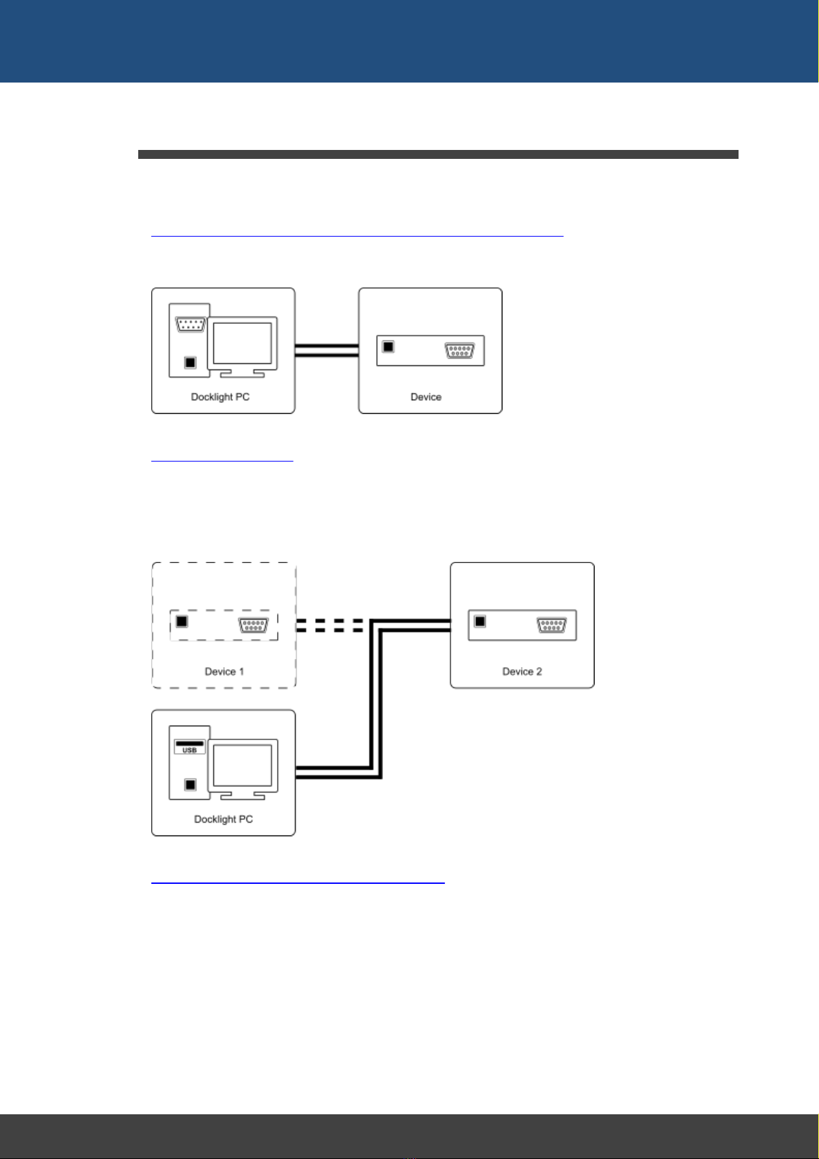
·Test the functionality or the protocol implementation of a serial device.
You may define control sequences recognized by your device, send them, log and
analyze the responses and test the device reaction.
·Simulate a serial device.
Although rare, the possibility of a hardware fault must be considered in most systems.
Imagine you have a device that sends an error message in the case of a hardware
fault. A second device should receive this error message and perform some kind of
reaction. Using Docklight you can easily simulate the error message to be sent and
test the second device's reaction.
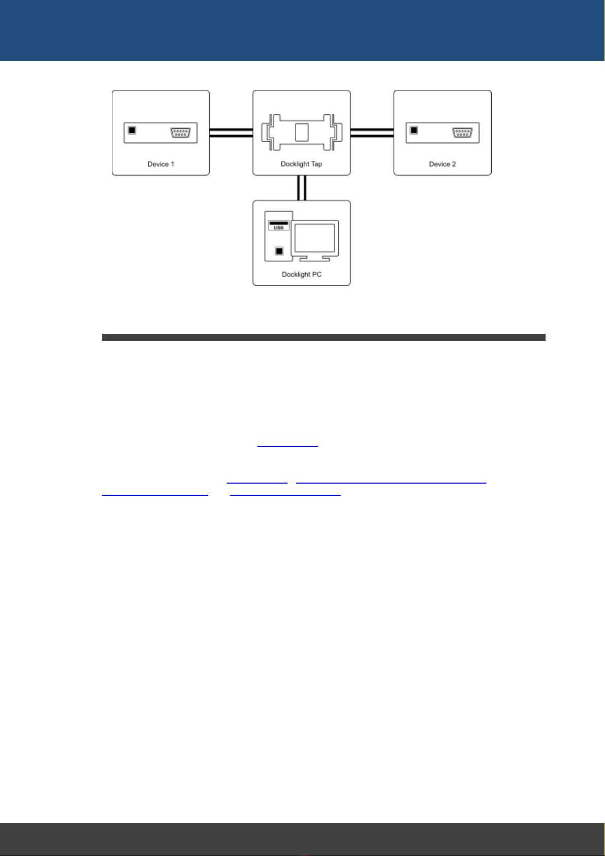
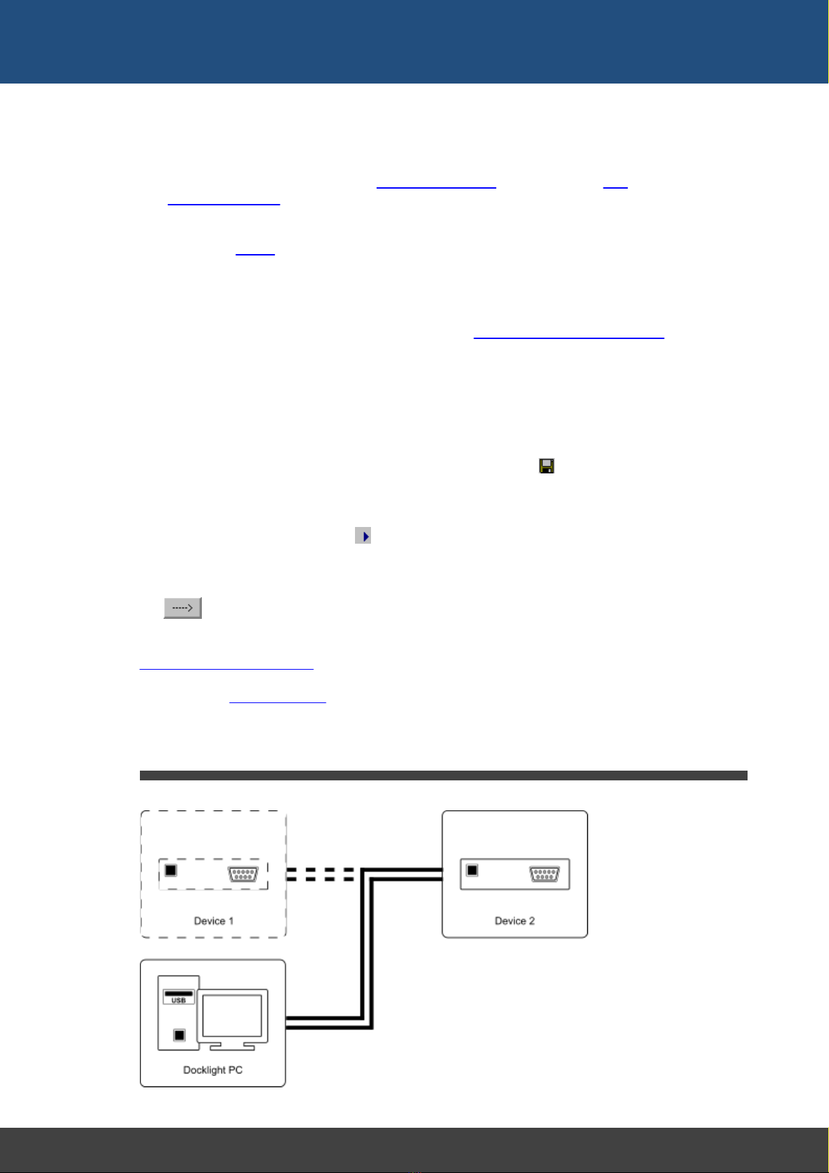
·Monitor the communication between two devices.
Insert Docklight into the communication link between two serial devices. Monitor and
log the serial communication in both directions. Detect faulty communication
sequences or special error conditions within the monitored communication. Take a
snapshot of the communication when such an error condition has occurred.
10
Docklight V2.2 User Manual 07/2016 Copyright 2016 Flachmann und Heggelbacher GbR
Introduction
2.3 System Requirements
Operating system
·Windows 10, Windows 10 x64, Windows 8, Windows 8 x64, Windows 7, Windows 7
x64, Windows Vista or Windows XP.
Additional requirements
·For RS232 testing or simulation: Minimum one COM port available. Two COM ports for
monitoring communication between two serial devices.
·For low-latency monitoring using Docklight Tap: One USB port
Additional cables or software drivers may be required for connecting the equipment to be
tested. See the sections on Docklight Tap, Docklight Monitoring Cable RS232 SUB D9,
Standard RS232 Cables and virtual null modem drivers.

User Interface
12
Docklight V2.2 User Manual 07/2016 Copyright 2016 Flachmann und Heggelbacher GbR
User Interface
3User Interface
3.1 Main Window
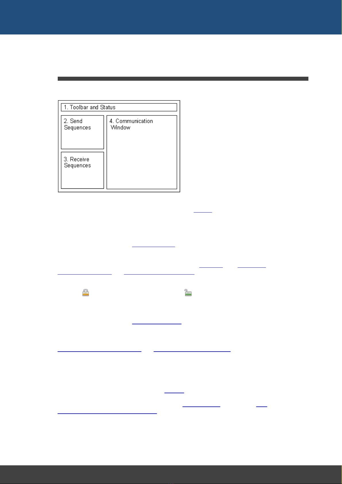
The main window of Docklight is divided into four sections:
1. Toolbar and Status
All main Docklight functions may be selected from the Toolbar. Additional information
about the communication status and the current settings is shown in the status line
below it.
2. Send Sequences
Define, edit and manage your Send Sequences here. Using the arrow symbol, the
selected sequence can be sent out immediately. Double click on the blank field at the
end of a list to create a new sequence. A context menu (right mouse button) is available
to cut, copy or paste entire Send Sequences to/from the Clipboard. See Editing and
Managing Sequences and Dialog: Edit Send Sequence for more information.
The sequence list can be reordered using drag&drop, after you enable it by clicking on
the small lock icon in the top left corner. When unlocked, the list can be changed
by dragging a sequence to a new position with the left mouse button pressed.
3. Receive Sequences
Define, edit and manage your Receive Sequences here. Double click on the blank field
at the end of a list to create a new sequence. The Receive Sequence list supports the
same reordering and clipboard operations as the Send Sequence list. You can also copy
a Send Sequence to the clipboard and paste it into the Receive Sequence list. See
Editing and Managing Sequences and Dialog: Edit Receive Sequence for more
information.
4. Communication Window
Displays the outgoing and incoming communication on the serial port. Various display
options are available for communication data, including ASCII / HEX / Decimal / Binary
display, time stamps and highlighting (see Options). If serial communication is stopped,
all data from the communications window may be copied to the clipboard or printed. You
may also search for specific sequences using the Find Sequence function. See How
Serial Data is Processed and Displayed for more information.

13
Docklight V2.2 User Manual 07/2016 Copyright 2016 Flachmann und Heggelbacher GbR
User Interface
3.2 Clipboard - Cut, Copy & Paste
Docklight supports the Windows clipboard and its Cut, Copy and Paste operations.
Clipboard operations are available in the
·Main Window - Send Sequences
·Main Window - Receive Sequences
·Main Window - Communication
·Main Window - Script Editor (Docklight Scripting only)
·Dialog: Edit Send Sequence
·Dialog: Edit Receive Sequence
·Dialog: Find Sequence
·Dialog: Send Sequence Parameter
·Notepad
·Keyboard Console
You can cut a serial data sequence from the communication window and create a new
Send or Receive Sequence by simply pasting it into the appropriate list. Or edit a Send
Sequence, copy a part of this sequence to the clipboard and create a new Receive
Sequence out of it by pasting it into the Receive Sequence window.
TIP: Try the right mouse button to display a context menu for Cut, Copy and Paste
operations.
3.3 Notepad
The Docklight Notepad is a separate window for writing down additional notes concerning
your Docklight project (how to use the Send / Receive Sequences, notes on additional
test equipment, etc.). The notepad window can be shown using the F12 key or the
menu Tools > Show Notepad.
The notepad is a simple text box that does not offer formatting menus or toolbars, but
you can paste formatted text from the Windows clipboard.
The notepad contents are stored along with all other Docklight project settings (see
saving and loading your project data). When opening a Docklight project file, the notepad
is displayed automatically, if project notes are available.
NOTE: Closing the notepad window does not delete your notes. They will be still
available when you press F12 again. To remove all notes, empty the text box using Ctrl
+A (Select All) and the DEL key.

Features and Functions

15
Docklight V2.2 User Manual 07/2016 Copyright 2016 Flachmann und Heggelbacher GbR
Features and Functions
4Features and Functions
4.1 How Serial Data Is Processed and Displayed
Docklight handles all serial data in an 8 bit-oriented way. Every sequence of serial data
consists of one or more 8 bit characters. Docklight allows you to
·display the serial data in either ASCII, HEX, Decimal or Binary format
·copy serial data to the clipboard and paste it into a standard text file or a formatted
Microsoft® Word document, or create a Send / Receive Sequence using the data.
·print out serial data, user comments and other information
Docklight's communication window shows the current communication on the selected
serial port(s). Docklight distinguishes between two communication channels (channel 1
and channel 2), which represent the incoming and outgoing data in Send/Receive Mode
or the two communication channels being observed in Monitoring Mode. Channel 1 and
channel 2 data are displayed using different colors or fonts, and the communication data
may be printed or stored as a log file in plain text or HTML format.
Besides the serial data, Docklight inserts date/time stamps into the communication
display. By default, a date/time stamp is inserted every time the data flow direction
switches between channel 1 and channel 2, or before a new Send Sequence is
transmitted. There are several options available for inserting additional time stamps. This
is especially useful when monitoring a half-duplex line with only one communication
channel. See Options --> Date/Time Stamps
Docklight is able to process serial data streams containing any ASCII code 0 - 255
decimal. Since there are non-printing control characters (ASCII code < 32) and different
encodings for ASCII code > 127, not all of these characters can be displayed in the
ASCII text window. Nonetheless, all characters will be processed properly by Docklight
and can be displayed in HEX, Decimal or Binary format. Docklight will process the serial
data on any language version of the Windows operating system in the same way,
although the ASCII display might be different. For control characters (ASCII code < 32),
an additional display option is available to display their text equivalent in the
communication window. See Options dialog and Appendix, ASCII Character Set Tables.
Docklight allows you to suppress all original serial data, if you are running a test where
you do not need to see the actual data, but only the additional evaluations generated
using Receive Sequences. See the Project Settings for Communication Filter.
4.2 Editing and Managing Sequences
A Docklight project mainly consists of user-defined sequences. These may be either
Send Sequences, which may be transmitted by Docklight itself, or Receive Sequences,
which are used to detect a special message within the incoming serial data.
Sequences are defined using the Edit Send Sequence or Edit Receive Sequence dialog
window. This dialog window is opened
1. by choosing Edit from the context menu available using the right mouse button.
2. by double-clicking on an existing sequence or pressing Ctrl + E with the Send
Sequence or Receive Sequence list selected.
3. when creating a new sequence by double-clicking on the blank field at the end of a list
(or pressing Ctrl + E).
4. when pasting a new sequence into the sequence list.

16
Docklight V2.2 User Manual 07/2016 Copyright 2016 Flachmann und Heggelbacher GbR
Features and Functions
Docklight supports the use of wildcards (e.g. wildcard "?" as a placeholder for one
arbitrary character) within Receive Sequences and Send Sequences. See the sections
sending commands with parameters and checking for sequences with random
characters for details and examples.

Working with Docklight
18
Docklight V2.2 User Manual 07/2016 Copyright 2016 Flachmann und Heggelbacher GbR
Working with Docklight
5Working with Docklight
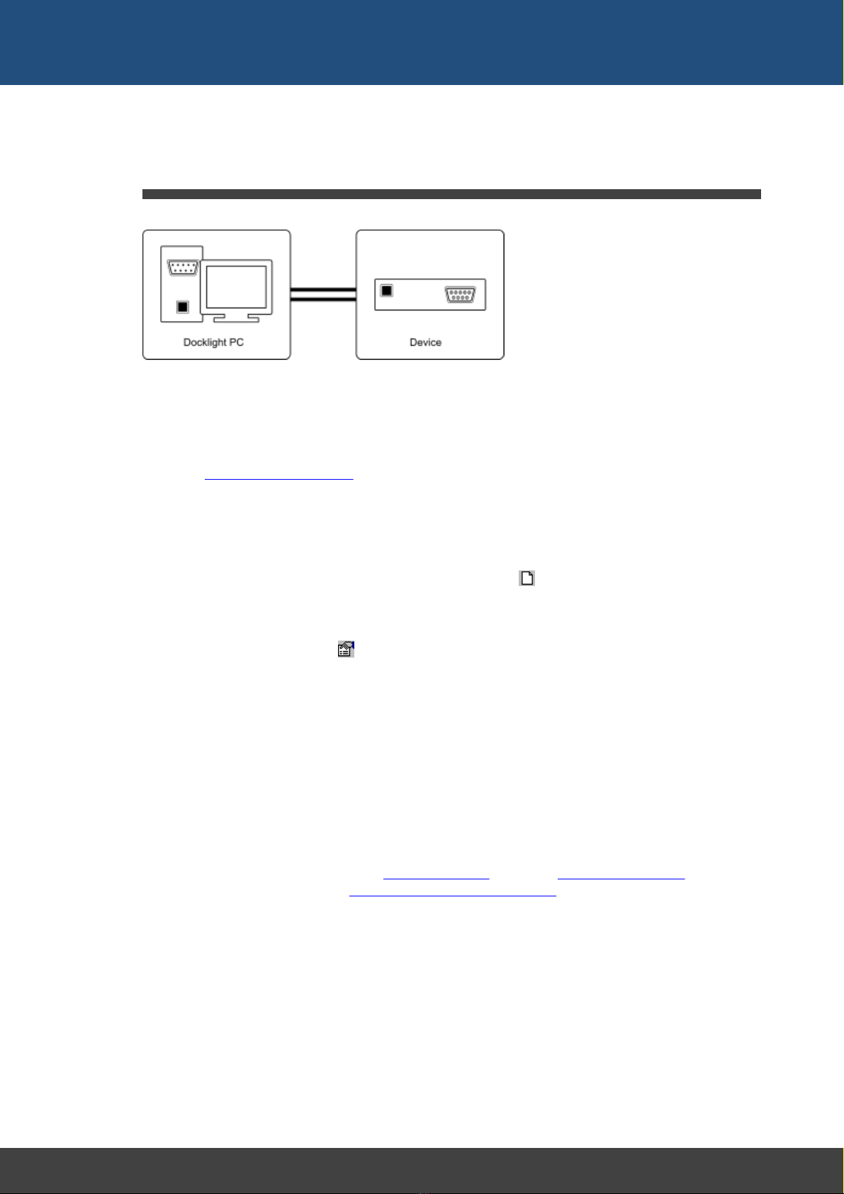
5.1 Testing a Serial Device or a Protocol Implementation
Preconditions
·You need the specification of the protocol to test, e.g. in written form.
·The serial device to test should be connected to one of the PC's COM ports. See
section Standard RS232 Cables for details on how to connect two serial devices.
·The serial device must be ready to operate.
Performing the test
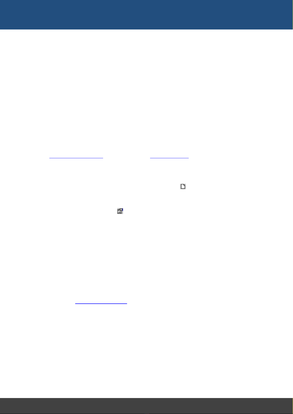
A) Creating a new project
Create a new Docklight project by selecting the menu File > New Project
B) Setting the Communication Options
1. Choose the menu Tools > Project Settings...
2. Choose communication mode Send/Receive
3. At Send/Receive on comm. channel, set the COM Port where your serial device
is connected.
4. Set the baud rate and all other COM Port Settings required.
5. Confirm the settings and close the dialog by clicking the OK button.
C) Defining the Send Sequences to be used
You will probably test your serial device by sending specific sequences, according to the
protocol used by the device, and observe the device's reaction. Perform the following
steps to create your list of sequences:
1. Double click on the last line of the Send Sequences table. The Edit Send Sequence
dialog is displayed (see also Editing and Managing Sequences).
2. Enter a Name for the sequence. The sequence name should be unique for every
Send Sequence defined.
3. Enter the Sequence itself. You may enter the sequence either in ASCII, HEX,
Decimal or Binary format. Switching between the different formats is possible at any
time using the Edit Mode radio buttons.
4. After clicking the OK button the new sequence will be added to the Send Sequence
lists.
Repeat steps 1 - 4 to define the other Send Sequences needed to perform your test.
D) Defining the Receive Sequences used
19
Docklight V2.2 User Manual 07/2016 Copyright 2016 Flachmann und Heggelbacher GbR
Working with Docklight
If you want Docklight to react when receiving specific sequences, you have to define a
list of Receive Sequences.
1. Double click on the last line of the Receive Sequences table. The dialog Edit
Receive Sequence is displayed. The dialog consist of three parts: Name field,
Sequence field, and Action field.
2. Edit the Name and Sequence fields.
3. Specify an Action to perform after the sequence has been received by Docklight.
There are four types of actions available:
Answer - After receiving the sequence, transmit one of the Send Sequences.
Comment - After receiving the sequence, insert a user-defined comment into the
communication window (and log file, if available).
Trigger - This is an advanced feature described in Catching a specific sequence...
Stop - After receiving the sequence, Docklight stops communications.
4. Click the OK button to add the new sequence to the list.
Repeat steps 1 - 4 to define the other Receive Sequences you need to perform your test.
E) Storing the project
Before running the actual test, it is recommended that the communication settings and
sequences defined be stored. This is done using the menu File > Save Project.
F) Running the test
Start Docklight by choosing Run > Start Communication.
Docklight will open a serial connection according to the parameters specified. It will then
display all incoming and outgoing communication in the communication window. Use
the Send button to send one of the defined sequences to the serial device. The
on-screen display of all data transfer allows you to check the device's behavior. All
protocol information can be logged in a text file for further analysis. Please see section
Logging and analyzing a test.
TIP: Using the notepad window (F12 key / menu Tools > Show Notepad), you can
easily take additional notes, or copy & paste parts of the communication log for further
documentation.
5.2 Simulating a Serial Device
20
Docklight V2.2 User Manual 07/2016 Copyright 2016 Flachmann und Heggelbacher GbR
Working with Docklight
Preconditions
·You need the specification of the behavior of the serial device you want to simulate,
e.g. what kind of information is sent back after receiving a certain command.
·A second device is connected to a PC COM port, which will communicate with your
simulator.
This second device and its behavior is the actual object of interest. An example could be
a device that periodically checks the status of an UPS (Uninterruptible Power Supply)
using a serial communication protocol. You could use Docklight to simulate basic UPS
behavior and certain UPS problem cases. This is very useful when testing the other
device, because it can be quite difficult to reproduce an alarm condition (like a bad
battery) at the real UPS.
NOTE: The second device may also be a second software application. It is possible to
run both Docklight and the software application on the same PC. Simply use a different
COM port for each of the two applications and connect the two COM ports using a
RS232 null modem cable. You can also use a virtual null modem for this purpose.
Performing the test
A) Creating a new project
Create a new Docklight project by selecting the menu File > New Project
B) Setting the Communication Options
1. Choose the menu Tools > Project Settings...
2. Choose communication mode Send/Receive
3. At Send/Receive on comm. channel, set the COM Port where your serial device
is connected.
4. Set the baud rate and all other COM Port Settings required.
5. Confirm the settings and close the dialog by clicking the OK button.
C) Defining the Send Sequences used
Define all the responses of your simulator. Think of responses when the simulated
device is in normal conditions, as well as responses when in fault condition. In the UPS
example mentioned above, a battery failure would be such a problem case that is hard to
reproduce with the original equipment. To test how other equipment reacts to a battery
failure, define the appropriate response sequence your UPS would send in this case.
NOTE: See Testing a serial device... to learn how to define Send Sequences.
D) Defining the Receive Sequences used
In most cases, your simulated device will not send unrequested data, but will be polled
from the other device. The other device will use a set of predefined command sequences
to request different types of information. Define the command sequences that must be
interpreted by your simulator here.
For every command sequence defined, specify Answer as an action. Choose one of the
sequences defined in C). If you want to use two or more alternative response sequences,
make several copies of the same Receive Sequence, give them a different name (e.g.
"status cmd - answer ok", "status cmd - answer battery failure", "status cmd - answer
mains failure") and assign different Send Sequences as an action. In the example, you
Table of contents


