Fläkt Woods 8217 GB 2014.07.02 20 Specifications are subject to alteration without notice
TopMaster Air Handling unit CONTROL AND REGULATION EQUIPMENT
1. Rotor, heating and cooling
Theunitiscongureddierentlywithregardtoheating,
heat recovery and cooling, see below.
Choice of heating function
• No heater
• Electric heater
• A water heater with frost-guard function
Heat recovery
• Continuously rotating heat exchangers
Choice of cooling
• No cooling
• Water -cooling
• DX cooling, 1-stage
Control function
Thecontrolfunctionworksasfollows:
Regardless of control mode the unit tries to achieve the
desired setpoint.
This is done by the unit depending on the needs,
demand for heat recovery, heating or cooling. Built into
the system is also a dead zone. The dead zone function
(usually2°C)actsasatemperaturezonebetweenheat
recovery and cooling unit where neither calls for heat re-
covery or cooling.
The reason for having a dead zone, is that the tempe-
rature will be slightly lower in winter, and slightly higher
insummer.Thisisenergy-ecientandinpracticeeven
more convenient for people staying in the room.
Room control and exhaust air control is the same
controltypewiththedierencethatincombinationwith
room control an external room sensor is needed (separate
orderingcode).Inadditionitispossibletouseoutdoor
temperature compensation. This control mode cannot be
combined with extract air control or room control.
Theunitisconguredforsupplyaircontrolasstan-
dard.Toobtainothercontrolmodes,rstthecontroller
must be changed from standard mode to cascade mode.
Then control mode is selected by changing the cascade
referencetoextractaircontrol/roomcontrol(0)oroutdo-
ortemperaturecompensation(1).Belowisadescription
ofthedierentcontrolmodes.
Supply air control
To maintain a constant supply air temperature, the con-
trollerworksfromaxedsetpointandthesupplyair
temperature. Based on these parameters, the controller
controls the current heating, heat recovery and cooling
sequences.
Extract air control
The exhaust air temperature gives a good average value
ofthetemperatureindierentrooms.Usingthisthe
unit controls the supply air temperature to maintain the
extract temperature at a desired level.
This method is suitable for ventilation systems that
supply a number of similar rooms. In cases where dif-
ferentroomshavedierentheatingrequirements,this
method should not be used. This is because the unit can-
not detect the varying heating needs, but can only read
an average temperature.
The limits on the supply air temperature (min. temp.
/max.temp.)ensurethatthesupplyairtemperatureis
maintained within the set range.
Default parameters for extract air control
1. Controller = 2 Selects cascade control
2. Cascade reference = 0 Selects extract air control
3. Cascade A = 0.5 When the sensor gets colder
than given setpoint value
4.CascadeB=–0.5 Whenthesensorgetshotter
than given setpoint value
5. Min. temp. = 15°C Sets lowest supply air
temperature
6. Max. temp. = 25°C Sets highest supply air
temperature
Example
1. Setpoint = 18°C
2. Extract air temperature = 16°C
This means that the new calculated setpoint for the
supply air controller is:
Calculatedsetpoint=setpoint+(setpoint–exhaustair
temperature)xcascadeA=18+(18-16)x0.5=19°C.
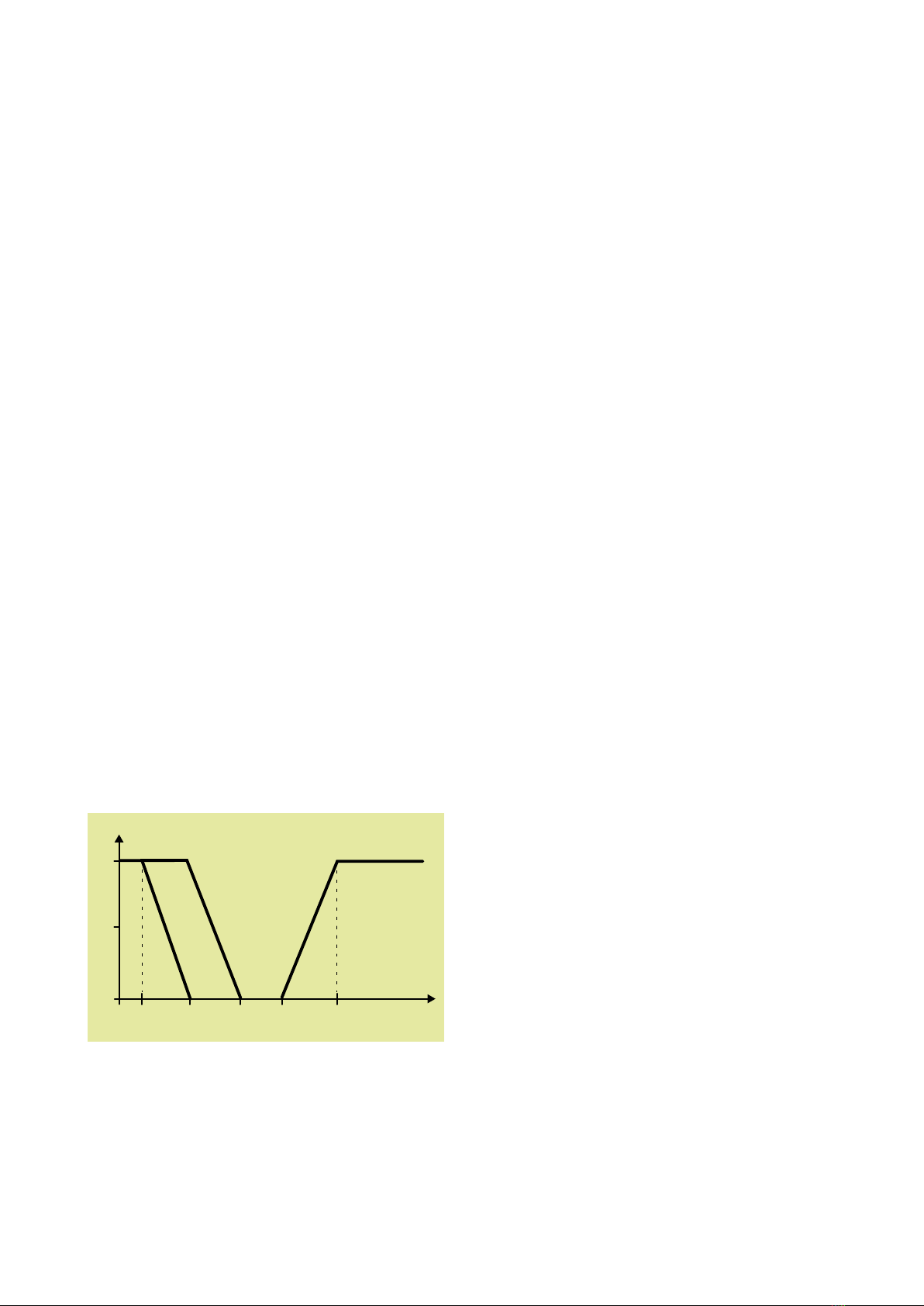
Figure 1. The figure shows the controller’s output signals to the
various unit components at different temperatures. The
figure also shows two temperatures, one for heating (T2)
and one for cooling (T3). The zone between T2 and T3 is
called the dead zone. Note that heating is activated only
when heat recovery is working at 100%.
2. Temperature controls
TopMaster has three temperature control options, supply
air, extract air control and room control.
Control functions
Heating
Recovery
Cooling
Control signal, %
Sequence control
Temperature, °C
100
50
T0 T1 T2 T3 T4


