Everwell FAHC18HA15 User manual
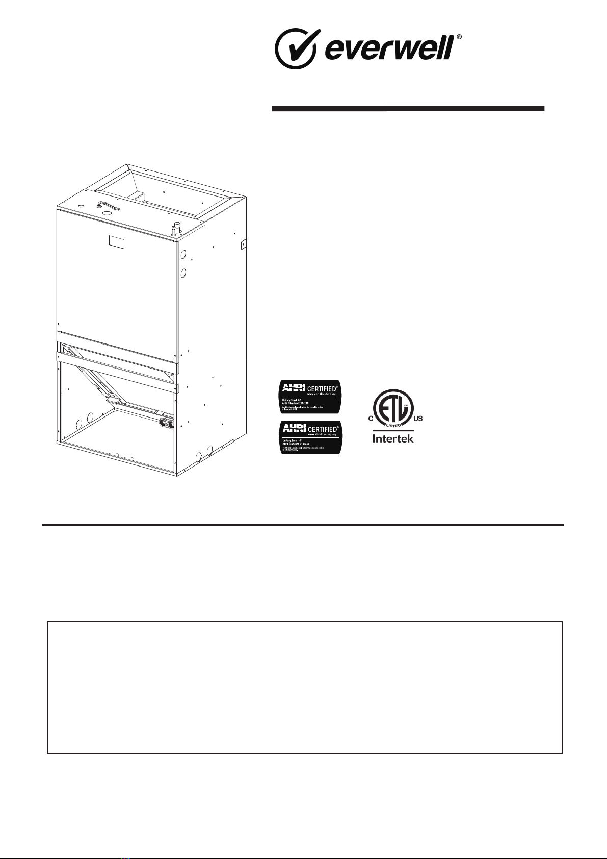
WALL-MOUNT AIR HANDLERS
1.5 to 3 Ton
secondary drain connections.
•Built-in filter rack.
•Wall-hanging brackets.
FAHC18HA15
FAHC24HA15
FAHC30HA15
FAHC36HA15
Installation Manual
Product Features
All phases of this installation must comply with NATIONAL, STATE AND LOCAL CODES.
Important: This Document is customer property and is to remain with this unit.
•Front or bottom return air.
•Blower slides out easily for maintenance.
•Painted finish on galvanized steel.
•Thermoplastic drain pan with bottom primary and
•208/230 VAC operation.
•Direct-drive, multi-speed motor allows air volume
variation for heating/cooling.
•Factory installed R410A orifice.
•Stud or wall mounting installation.
•Fully insulated cabinet.
•3/4'' NPT primary and secondary drains.
•AHRI certified and ETL listed.
•
2.5, 5, 7.5 and 10 kW single phase electric heaters.
The manufacturer has a policy of continuous data improvement and it
reserves the right to change design and specifications without notice.

2

......................................................................................4
Dimension Data.........................................................................................6
Installation Instructions .............................................................................9
Wiring........................................................................................................13
Safety Precaution
Table of Contents
3
Performance Data....................................................................................15
. ......................................................................14..
Electric Wiring Gauge

Important:
These instructions do not cover all variations in systems
nor provide for every possible contingency to be met in connection
with the installation. Should further information be desired or should
particular problems arise which are not covered sufficiently for the
purchaser’s purposes, the matter should be referred to your
installing dealer or local distributor.
Important:
Installation of this unit shall be made in accordance with
the National Electric Code, NFPA No. 90A and 90B, and any other
local codes or utilities requirements.
Note:
The small air handlers have been evaluated in accordance
with the Code of Federal Regulations, Chapter XX, Part 3280 or the
equivalent. “SUITABLE FOR MOBILE HOME USE.”
WARNING
WARNING
WARNING
WARNING
WARNING
WARNING
Respirable particles of fiberglass are known to State of California
to cause cancer.
for safety. California Proposition 65 warnings are required for
certain products, which are not covered by the OSHA standards.
California’s Proposition 65 requires warnings for products sold in
California that contain or produce any of over 600 listed
chemicals known to the State of California to cause cancer or
birth defects such as fiberglass insulation, lead in brass, and
combustion products from natural vapor.
All “new equipment” shipped for sale in California will have labels
stating that the product contains and/or produces Proposition
65 chemicals. Although we have not changed our processes,
having the same label on all our products facilitates
manufacturing and shipping. We cannot always know “when, or
if” products will be sold in the California market.
You may receive inquiries from customers about chemicals found
air-conditioning equipment, or found in natural vapor used with
some of our products. Listed below are those chemicals and
substances commonly associated with similar equipment in our
industry and other manufacturers.
Glass Wool (Fiberglass) Insulation
Carbon Monoxide (CO)
Formaldehyde
Benzene
More details are available at the websites for OSHA
www.osha.gov and the State of California’s OEHHA (Office of
Environmental Health Hazard Assessment), at www.oehha.org.
Consumer education is important since the chemicals and
substances on the list are found in our daily lives. Most
consumers are aware that products present safety and health
risks, when improperly used, handled and maintained.
4
Section 1. Safety Precaution
SAFETY HAZARD!
This information is intended for use by individuals possessing
adequate backgrounds of electrical and mechanical
experience. Any attempt to repair a central air conditioning
product may result in personal injury and/or property
damage. The manufacturer or seller cannot be responsible for
the interpretation of this information, nor can it assume any
liability in connection with its use.
HAZARDOUS VOLTAGE!
Disconnect all electrical power, including remote disconnects
before installing or servicing. Follow proper lockout/tagout
procedures to ensure the power can not be inadvertently
energized. Failure to disconnect power before servicing could
result in death or serious injury.
LIVE ELECTRICAL COMPONENTS!
During installation, testing, servicing, and troubleshooting of
this product, it may be necessar y to work with live electrical
components. Failure to follow all electrical safety precautions
when exposed to live electrical components could result in
death or serious injury.
EXPLOSION HAZARD!
Do not store corrosive or combustible materials, gasoline, or
other flammable vapors or liquids near the unit. Failure to
follow this warning could result in property damage, serious
personal injury, or death.
ELECTRICAL HAZARD!
Grounding Required! Follow proper local and state electrical
code on requirements for grounding. Failure to follow this
warning could result in property damage, serious personal
injury, or death.
HAZARDOUS VAPORS!
Do not install an air handler with a non-ducted return in the
same closet, alcove, or utility room as a fossil fuel device.
Hazardous vapors can be distributed throughout the
conditioned space and equipment damage can result.
WARNING
PROPOSITION 65: This appliance contains fiberglass insulation.
(Occupational Safety and Health Administration), at
All manufacturer products meet current federal OSHA Guidelines
found in, or produced by, some of our heating and
CAUTION
CAUTION
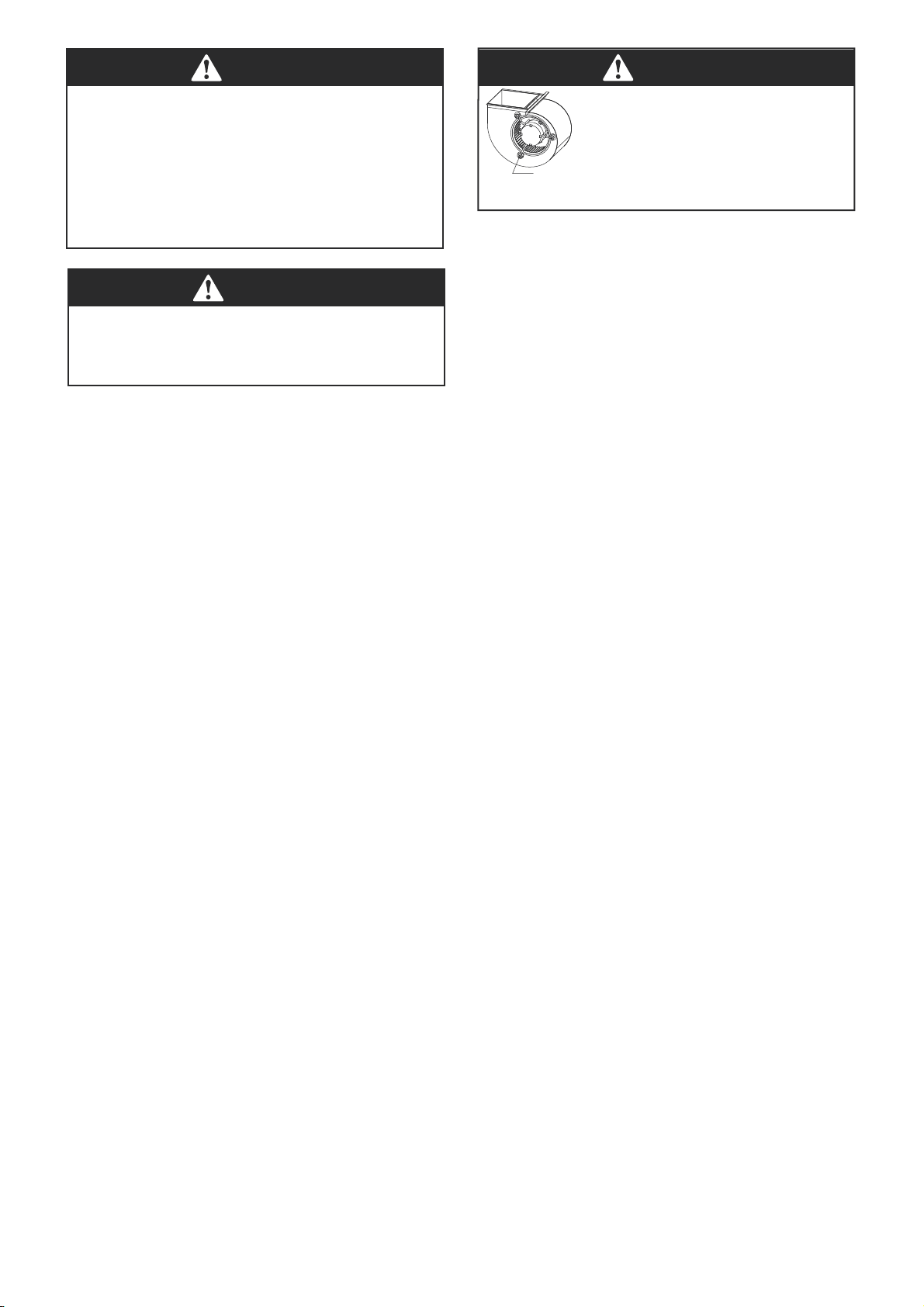
WARNING
Make sure the blower motor support is tight
(3-motor mount bolts) then check to see if
wheel is secured to motor shaft before
operating unit.
BLOWER MOT
OR
SHIPPING BOLT
5
CORROSION HAZARD!
To prevent shortening its service life, the air handler should
not be used during the finishing phases of construction. The
low return air temperatures can lead to the formation of
condensate. Condensate in the presence of chlorides and
fluorides from paint, varnish, stains, adhesives, cleaning
compounds, and cement creates a corrosive condition which
may cause rapid deterioration of the cabinet and internal
components.
SAFETY HAZARD!
Sharp Edge Hazard. Be careful of sharp edges on equipment
or any cuts made on sheet metal while installing or servicing.
Personal injury may result.

2.1 Unit Dimensions
6
Section 2. Dimension Data
All units are configured for vertical upflow.
Units cannot be installed in any other configuration.
Front return shown. Units may
also be installed as bottom
return. See the applications
section for more details.
1
D
D
H
High voltage connection
7/8" dia knock outs
Liquid line connection
copper (Sweat)(3/8"dia pipe)
Vapor line connection
copper (Sweat)(3/4"dia pipe)
Low voltage
connection
High voltage connection
1-2/25" dia knock outs
High voltage connection
7/8" dia knock outs
Primary drain conncetion 3/4"
female pipe thread (NPT)
Auxiliary drain connection 3/4"
female pipe thread (NPT)
Model
Dimensions- In. (mm) Unit Weight /
Shipping Weight
Lbs. (kg)
Height
H
Width
W
Width
W1
Depth
D
Depth
D1
18K36 (915) 20-1/2 (522)17-2/5 (442) 15 (381) 9-3/5 (244)88 / 99 (40 / 45)
24K36 (915) 20-1/2 (522)17-2/5 (442) 15 (381) 9-3/5 (244)88 / 99 (40 / 45)
7
Model
Dimensions- In. (mm) Unit Weight /
Shipping Weight
Lbs. (kg)
Height
H
Width
W
Width
W1
Depth
D
Depth
D1
30K39-3/5 (1006) 22 (559) 18-4/5 (477)19 (485)10 (251)110/ 121 (50 / 55)
36K39-3/5 (1006) 22 (559) 18-4/5 (477)19 (485)10 (251)110/ 121 (50 / 55)
Low voltage
connection
All units are configured for vertical upflow.
Units cannot be installed in any other configuration.
Auxiliary drain connection 3/4"
female pipe thread (NPT)
Primary drain conncetion 3/4"
female pipe thread (NPT)
Front return shown. Units may
also be installed as bottom
return. See the applications
section for more details.
D1
D
W
W1
H
High voltage connection
-1 3/8" dia knock outs
Liquid line connection
copper (Sweat)(3/8"dia pipe)
Vapor line connection
copper (Sweat)(3/4"dia pipe)
High voltage connection
7/8" dia knock outs
High voltage connection
-1 3/8" dia knock outs
ABC
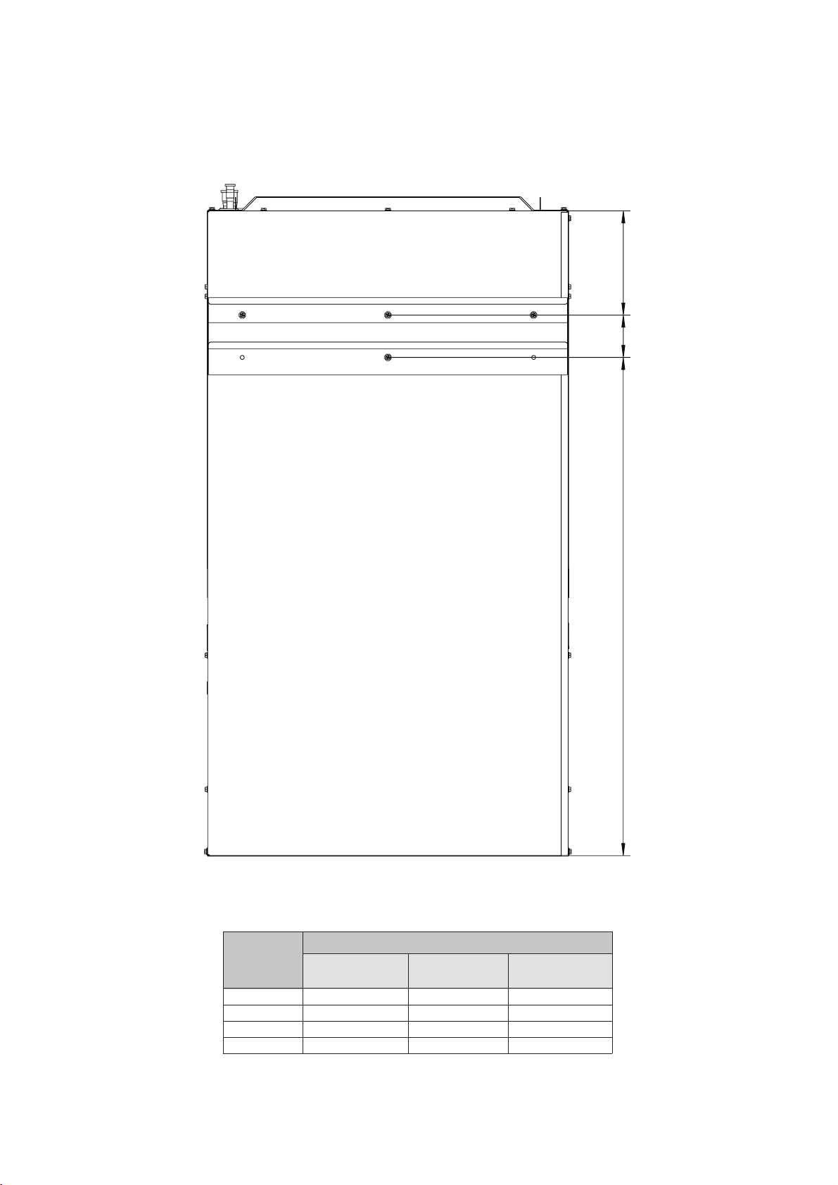
2.2 Unit Back Dimensions
Model
Dimensions- In. (mm)
A B C
18K5-3/8 (136)2-2/5 (61) 28-1/4 (718)
24K5-3/8 (136)2-2/5 (61) 28-1/4 (718)
30K6 (151)2-2/5 (61)31-1/4 (794)
36K6 (151)2-2/5 (61)31-1/4 (794)
8

Unpack unit and move to final location. Remove carton, taking care not
to damage unit. Remove protective sheet metal from the base of the
unit, if equipped. Inspect equipment for damage prior to installation.
Locate rating plate on unit. It contains information needed to properly
install unit. Check rating plate to be sure unit matches job specifications.
A front access panel is provided, which permits access to blower assembly
The small air handler should be centrally located and may be
installed in a closet, alcove, utility room, or basement. Minimum
clearances must be met.
The air handler comes standard with two different options for mounting,
wall mount or frame mount. Both mounting options require the unit to
be level from side to side and from front to back in order to allow
condensate to properly drain from the unit. Failure to do this will result
in condensate leaking out from the unit, potentially causing structural
damage to the surrounding support structures, dry wall, carpet, etc.
Also, both mounting structures require the ability to accommodate a
minimum of 150 lb load. Failure to do this will cause damage to the
support structure and potentially damage the unit.
The air handler comes standard with a wall mounting bracket and air
handler mounting bracket. Reference Figure 3-1 for more details.
1. Remove lower wall mounting bracket from the back of the unit by
removing one screw which attaches the bracket to the air handler.
Note: Discard the screw after you have removed the wall mounting
bracket.
2. Install bracket on the wall by using 3 wood screws (not provided).
Make sure the bracket is level in order to provided proper drainage
from the unit. Note: Do not attach the wall mounting bracket into
unsupported dry wall. Make sure that the wood screws are going into a
structure that can suppport a minimum load of 150 lb.
3. Lift the air handler above the wall mounting bracket and attach the
unit to the installed bracket. Reference Figure 3-1.
4. Install the additional bottom plate for extra support for this type
mounting (see figure 3-1).
Note: The additional plate is shipped in the bottom of the shipping
carton.
3.2.1 Wall Mount
Fig. 3-2 Frame Mount
3.2.2 Frame Mount
PROVIDED WALL
MOUNT BRACKET
WALLMOUNT BRACKET
WOOD SCREWS
SUPPORTING 2˝X4˝
STRUCTURE
WALL STRUTURE
WOOD SCREWS
WOOD SCREWS
PROVIDED WALL
MOUNT BRACKET
STRUCTURE MUST BE ABLE TO SUPPORT A
MINIMUM OF 150 LBS.
PROVIDED AIR HANDLER
WOOD SCREWS
3.2 Location
NOTE:
IN ORDER TO PREVENT
AIR LEAKAGE,THE TABS
AND SCREW HOLES
NEED TO BE SEALED
UP WHEN THEY ARE
NOT TO BE USED.
OFFSET HANGING
BRACKET
IMPORTANT:
The (8) wood screws are not provided with the unit.
#12 x 1 ½˝ wood screws are recommended. When the unit is installed
on a wood frame, the screws should be used to fix the unit to the
studs. If they are not used, the unit may fall down or cause other
damage. See Figure 3-2 for frame mount installation.
The air handler comes with 8 clearance holes (4 on each side). These
holes are used to mount the air handler inside of a frame structure
(see Figure 3-2). When mounting in this fashion, make sure that the
wood screws are mounted from within the air handler and not from
outside the unit in order to avoid damaging the coil. If the frame does
not provide support in the front of the unit and additional support is
needed, open up the tabs and fix the unit to the frame or other
support structure with screws. Select a solid and level site to ensure
proper installation of the frame mount. Verify that there is sufficient
space for installation and maintenance.(see Figure. 3-3)
WALL STRUCTURE
SUPPORTING
2˝X4˝ STRUCTURE
WOOD SCREWS
SUPPORTING
2˝X4˝ STRUCTURE
STUD ATTACHMENT
HOLES
THE TABS
BRACKET PLACEMENT FOR
HANGING IN A CLOSET
(ONLY FOR 30K/36K)
9
Section 3. Installation Instructions
3.1 Unpacking
Fig. 3-1 Wall Mount
NOTE: MOUNTING WALL AND SUPPORTING
and electrical controls for removal and servicing.
File claim with shipping company if shipment is damaged or incomplete.
MOUNTING BRACKET
Field ductwork must comply with the National Fire Protection
Association NFPA 90A, NFPA 90B and any applicable local
ordinance.
WARNING
Sheet metal ductwork run in unconditioned spaces must be insulated
and covered with a vapor barrier. Fibrous ductwork may be used if
constructed and installed in accordance with SMACNA Construction
Standard on Fibrous Glass Ducts. Ductwork must comply with
National Fire Protection Association as tested by U/L Standard 181
for Class I Air Ducts. Check local codes for requirements on
ductwork and insulation.
• Duct system must be designed within the range of external static
pressure the unit is designed to operate against. It is important that
the system airflow be adequate. Make sure supply and return
ductwork, grilles, special filters, accessories, etc. are accounted for in
total resistance. See airflow performance tables in this manual.
• Design the duct system in accordance with “ACCA” Manual “0”
Design for Residential Winter and Summer Air Conditioning and
Equipment Selection. Latest editions are available from: “ACCA” Air
Conditioning Contractors of America. If duct system incorporates
flexible air duct, be sure pressure drop information (straight length
plus all turns) shown in “ACCA” Manual “D” is accounted for in
system.
• Supply plenum is attached to the 3/4” duct flanges supplied with
the unit.
• IMPORTANT: If an elbow is included in the plenum close to the
unit, it must not be smaller than the dimensions of the supply duct
flange on the unit.
•IMPORTANT: If connected to the blower casing, the front flange
on the return duct must not be screwed into the area where the
power wiring is located. Drilles or sharp screw points can damage
insulation on wires located inside unit.
• Secure the supply and return ductwork to the unit flanges, using
proper fasteners for the type of duct used and tape the duct-to-unit
joint as required to prevent air leaks.
The unit is supplied with primary and auxiliary condensate drains
that have 3/4” NPT connections. Both drains must be trapped outside
the unit and piped in accordance with applicable materials and
building codes. Do not reduce the drain line size less than the
connection size on the drain pan. Condensate should be piped to an
open drain or to the outside. All drains must pitch downward away
from the unit a minimum of 1/4” per foot of line to ensure proper
drainage. Insulate the primary drain line to prevent sweating where
dew point temperatures may be met. (Insulation is optional depending
on climate and application needs.)
Important:
If cleanout Tee is used, standpipe must be sealed/capped.
10
3.3 Duct Work
Do not, under any circumstances, connect return ductwork to
any other heat producing device such as fireplace insert,
stove, etc. Unauthorized use of such devices may result in fire,
carbon monoxide poisoning, explosion, personal injury or
property damage.
3.4 Condensate Drain
Fig.3-3 Space for Frame Mount
Top view of the indoor unit clearance (including air duct).
≥0" ≥0"
≥24"
≥0"
Front of unit
WARNING
Supply duct is intended to handle conditioned air for
circulation through a duct supplying only one room. Room
space may be partitioned into rooms within the same unit,
but supply air is not to be delivered to any other rooms.
AIRFLOW
≥20"
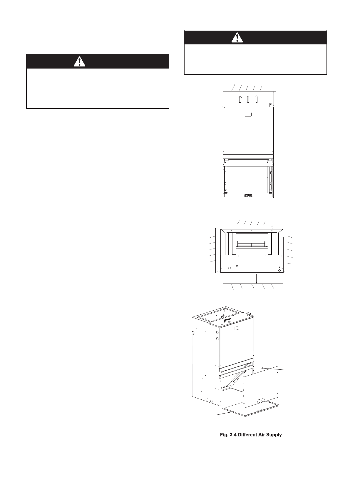
Remove the cross brace when converting cabinet to bottom return.
REMOVE BOTTOM COIL
PANEL OFF PLATE
INSTALL FRONT
COIL PANEL
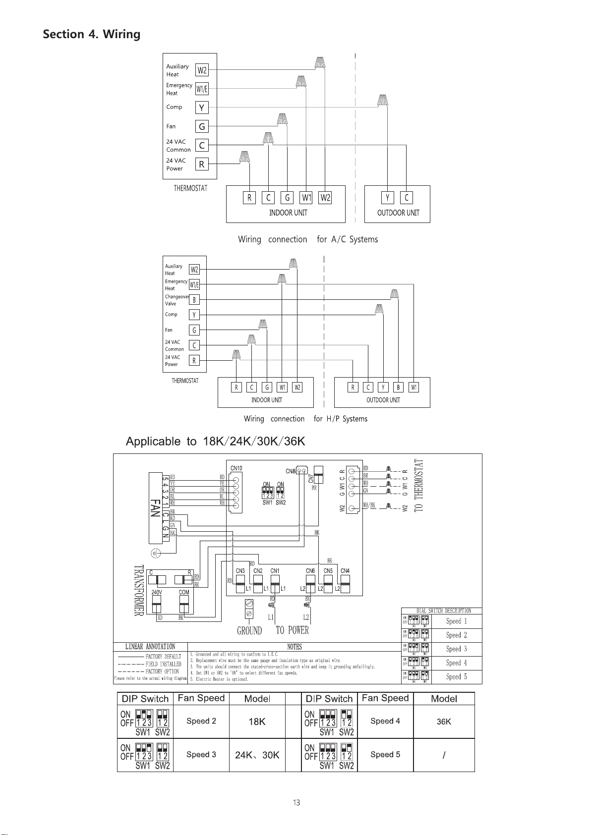
•Low voltage control connections are made to low voltage pigtails
extending from top of air handler. Connections for control wiring
are made with wire nuts. Control wiring knockouts (7/8˝) are also
provided on the right and left side of the unit for side connection.
•See wiring diagrams attached to indoor and outdoor sections to be
connected.
• Make sure, after installation, separation of control wiring and power
wiring has been maintained.
3.8.3 Grounding
•Grounding may be accomplished when installed in accordance with
electrical codes by bonding the metal conduit to the unit cabinet or by
attaching ground wire(s) to ground lug(s) provided in the unit wiring
compartment.
•Ground lug(s) are located close to wire entrance on left side of unit
(upflow). Lug(s) may be moved to marked locations near wire
entrance on right side of unit (upflow) if alternate location is more
convenient.
•Use of multiple supply circuits require grounding of each circuit to
lug(s) provided in unit.
•If required, install a branch circuit disconnect of adequate size,
located within sight of, and readily accessible to the unit.
•
IMPORTANT: After the Electric Heater is installed, units are equipped
with one 60 amp. circuit breaker. These breaker(s) protect the internal
wiring in the event of a short circuit and serve as a disconnect. Circuit
breakers installed within the unit do not provide over-current protection
of the supply wiring and therefore may be sized larger than the
branch circuit protection.
•Supply circuit power wiring must be 75°C minimum copper
conductors only. See Electrical Data in this section for ampacity, wire
size and circuit protector requirements. Supply circuit protective devices
may be either fuses or “HACR” type circuit breakers.
• Power wiring may be connected to either the right or left side. Two
7/8” dia. concentric knockouts are provided for connection of power
wiring to unit.
•Power wiring is connected to the power cable in unit electric cabinet.
3.8.2 Control Wiring
IMPORTANT: Class 2 low voltage control wiring should not be run in
conduit with main power wiring and must be separated from power
wiring, unless class 1 wire of proper voltage rating is used.
•Low voltage control wiring should be 18 AWG. color-coded. For
lengths longer than 100 ft., 16 AWG. wire should be used.
Field wiring must comply with the National Electric Code (C.E.C. in Canada
) and any applicable local ordinance.
3.8.1 Power Wiring
It is important that proper electrical power is available for connection
to the unit model being installed. See the unit nameplate, wiring diagram
and electrical data in the installation instructions.
WARNING
3.5 Refrigerant Piping
Refrigerant pipe connections are located on the top of the unit.
Refrigerant piping external to the unit shall be sized in accordance
with the instructions of the outdoor equipment. When units are
recessed mounted in the wall, make certain that piping connections
are pressure tested prior to the wall being closed. While brazing, be
sure to protect the cabinet and grommets from heat damage.
All units are shipped and installed with an orifice designed for air
conditioning or heat pump operation. Pressures equalize after
shut down. Some outdoor models may require a start assist kit.
See outdoor unit for more information.
3.8 Wiring
This unit is supplied with a multi-speed motor with a direct drive
blower wheel which can obtain various air flows. The unit is shipped
with factory set cooling and heating speed taps. Airflow performance
tables are available for additional speed taps. Disconnect all power to
the unit before making any adjustments to the motor speed taps. Be
sure to check the air flow and the temperature drop across the
11
3.6 Metering Device
3.7 Blower
Disconnect all power to unit before installing or servicing.
More than one disconnect switch may be required to de-
energize the equipment. Hazardous voltage can cause severe
personal injury or death.
evaporator coil to ensure sufficient air flow.
The unit must be permanently grounded. Failure to do so can
result in electrical shock causing personal injury or death.
WARNING
Select a thermostat that is commonly used with HP or AC single
stage heating/cooling with electric heat. The thermostat will energize
the fan on a demand for heating or cooling.
Install the thermostat on an inside wall, away from drafts, lights or
other heat sources in a location that has sufficient air circulation from
other rooms being controlled by the thermostat. The thermostat
should be mounted 4 to 5 feet above the floor.
3.10 Thermostat
An air filter must be installed before air enters the evaporator coil in
order to protect the coil, blower, and other internal parts from
excessive dirt and dust . A filter must be installed. Consult the filter
manufacturer for proper sizing and maximum velocity requirements.
3.9 Air Filter
Filter Sizes
18K/24K15*19 [381*483]
Model Filter Sizes in. [mm]
30K/36K20*20 [508*508]
MODEL
VOLTAGE HERTS HP RPM SPEEDS CIRCUIT
AMPS.
MAXIMUM CIRCUIT
PROTECTOR
18K 208/230 60 1/3 960 5 1.9 3(A)
24K 208/230 60 1/3 1010 5 2.2 3(A)
30K 208/230 60 1/2 960 5 2.6 3(A)
36K 208/230 60 1/2 1000 5 3.2 6(A)
3.8.4 Electrical Data

12
3.12 Operational And Checkout Procedures
To obtain proper performance, all units must be operated and charge
adjustments made in accordance with procedures found in the Service
Facts document of the outdoor unit.
After installation has been completed, it is recommended that the entire
system be checked against the following list:
1. Be sure unit suspension (if used) is secure and there are no tools or
loose debris in, around or on top of the unit.
2. Properly insulate suction lines and fittings.
3. Properly secure and isolate all refrigerant lines.
4. Verify that all electrical connections are tight.
5. Check all duct outlets; they must be open and unrestricted.
6. Check drain lines and be sure all joints are tight.
7. Be sure the return air filter is installed.
8. Operate complete system in each mode to verify proper
performance. Verify operation of supplementary electric heater.
The system air filter(s) should be inspected, cleaned or replaced at least
monthly. Make certain that the access panels are replaced and secured
properly before placing the unit back in operation. This product is
designed for dependable service; however, periodic maintenance should
be scheduled and conducted by trained professional service personeel.
This service should be conducted at least annually, and should include
testing and inspection of electrical and refrigerant components. The heat
transfer surface should be cleaned. The blower motor is permanently
lubricated for normal operating conditions.
3.13 Maintenance
Cooling (heat pump)
Constant torque version – When the thermostat calls for cooling, the
circuit from R to G is completed. The blower motor is energized
directly by the 24VAC signal from the thermostat.
The circuit from R to Y is also completed, energizing the compressor
contactor of the outdoor unit. The contactor will close and start the
compressor and condenser fan motor.
Circuit R to B energizes the reversing valve to the heating position.
Heating (heat pump)
Constant torque version – When the thermostat calls for heating, the
circuit from R to G is completed and the blower motor is energized
directly by the 24VAC signal from the thermostat.
The circuit from R to Y is also completed, energizing the compressor
contactor of the outdoor unit. The contactor will close and start the
compressor and condenser fan motor.
If the indoor temperature continues to fall, the R to W2 circuit is
completed, energizing the electric heat contactor(s).
Heating (electric heat only)
Note: The thermostat must be setup to bring the blower on when the
electric heat is energized.
Constant torque version - When the thermostat calls for heating, the
circuit from R to G is completed and the blower motor is energized
directly by the 24VAC signal from the thermostat. The circuit from R
to W1 is completed energizing the heating contactor(s).
Defrost
Supplemental heat during defrost can be provided by connecting the
W1 (white) wire from the outdoor unit to W1 at the indoor unit. This will
prevent cold air from being discharged from the indoor unit during
defrost.
Low voltage control wiring should be 18 AWG, color coded (105 degree
C minimum). For lengths longer than 100ft., 16 AWG wire should be
used. Make certain that separation of control wiring and power wiring
has been maintained.
If the indoor temperature continues to fall, the R to W2 circuit is
completed, energizing the electric heat contactor(s).
contactor of the outdoor unit. The contactor will close and start the
compressor and condenser fan motor.
3.11 Sequence of Operation
Constant torque version – When the thermostat calls for cooling, the
circuit from R to G is completed. The blower motor is energized directly
by the 24VAC signal from the thermostat.
Cooling (cooling only)
The circuit from R to Y is also completed, energizing the compressor
14
Section 5. Electric Wiring Gauge
Note:
The cross-section areas of wires or lines should not be less than the corresponding ones listed in the table below;
Besides, if the power wires is quite long from the unit, please choose the windings with larger cross-section area
to guarantee the normal power supply.
Model ( )cooling only type
18K
24K
30K
36K
Line
Gauge
Indoor Unit
Power Line
Line Quantity
3
3
3
3
Line Diameter(AWG)
16
16
16
16
Outdoor
Unit Power
Line
3
3
3
3
14
14
12
12
Indoor-
Thermostat
Singal Line
5
5
5
5
18
18
18
18
Outdoor-
Thermostat
Singal Line
2
2
2
2
18
18
18
18
Line Quantity
Line Diameter(AWG)
Line Quantity
Line Diameter(AWG)
Line Quantity
Line Diameter(AWG)
Model ( ) cooling & heating type
18K
24K
30K
36K
Line
Gauge
Indoor Unit
Power Line
Line Quantity
3
3
3
3
Line Diameter(AWG)
16
16
16
16
Outdoor
Unit Power
Line
3
3
3
3
14
14
12
12
Indoor-
Thermostat
Singal Line
5
5
5
5
18
18
18
18
Outdoor-
Thermostat
Singal Line
5
5
5
5
18
18
18
18
Line Quantity
Line Diameter(AWG)
Line Quantity
Line Diameter(AWG)
Line Quantity
Line Diameter(AWG)

15
Section 6. Performance Data
Airflow performance data is based on cooling performance with a coil and no filter in place. Select performance table for appropriate unit size
external static applied to unit allows operation within the minimum and maximum limits shown in table below for both cooling and electric heat
operation.
Airflow Performance (Standard CFM)
The air distribution system has the greatest effect on airflow. The duct system is totally controlled by the contractor. For this reason, the contractor
should use only industry-recognized procedures.
Heat pump systems require a specified airflow. Each ton of cooling requires between 350 and 450 cubic feet of air per minute (CFM), or 400 CFM
nominally.
Duct design and construction should be carefully done. System performance can be lowered dramatically through bad planning or workmanship.
Air supply diffusers must be selected and located carefully. They must be sized and positioned to deliver air along the perimerter of the space. If
they are too small for their intended airflow, they become noisy. If they are not located properly, they cause drafts. Air grilles must be properly sized
to carry air back to the blower.If they are too small, they also cause noise.
The installers should balance the air distribution system to ensure proper quiet airflow to all rooms in the home. This ensures a comfortable living
space.
1. Airflow based upon dry coil at 230V with no electric heat and no filter. For 18, 24, 30 and 36 sizes, airflow at 208V is approximately the same
as 230V because the mult-tap ECM motor is a constant torque motor. The torque doesn’t drop off at the speeds in which the motor operates.
2. Airflow is equivalent for front or bottom return configurations.
NOTES:
0 0.1 0.2 0.3 0.4 0.5 0.6 0.7 0.8
1 812 783 741 698 669 619 586 525 474
2-Factory Default 916 875 851 812 786 746 717 673 634
3 1005 978 941 917 882 856 819 792 752
4
5
1 812 783 741 698 669 619 586 525 474
2 916 875 851 812 786 746 717 673 634
3-Factory Default 1005 978 941 917 882 856 819 792 752
4
5
1 1059 1009 960 921 871 829 751 692 616
2 1150 1116 1069 1036 988 953 912 850 779
3-Factory Default 1282 1235 1203 1158 1131 1076 1050 1015 953
4 1404 1374 1335 1306 1265 1231 1195 1150 1115
5 1575 1534 1492 1446 1401 1331 1239 1132 1025
1 1059 1009 960 921 871 829 751 692 616
2 1150 1116 1069 1036 988 953 912 850 779
3 1282 1235 1203 1158 1131 1076 1050 1015 953
4-Factory Default 1404 1374 1335 1306 1265 1231 1195 1150 1115
5 1575 1534 1492 1446 1401 1331 1239 1132 1025
Model
Blower Speeds
36K
18K
24K
30K
External Static Pressure(in.w.c)

This manual suits for next models
3
Table of contents
Popular Air Handler manuals by other brands

S&P
S&P UTV-2 ECOWATT manual

Stealth
Stealth SC-24CD-UM owner's manual

CyClone
CyClone DV160 Installation and operation instructions

Maytag
Maytag Amana AMVT P1400 Series Installation & operating instructions

Trane
Trane CeilAir CW Installation, operation and maintenance

Vents
Vents VUT 2000 PBE EC user manual

Trox Technik
Trox Technik X-CUBE operating instructions

Vents
Vents VUE 300 PBE EC user manual

Vision
Vision CAC 003G - 090G Installation and maintenance manual

Trane
Trane Hyperion AM8A0A24V21CA Series Field Reference Data

TCF
TCF ZAE Series Installation, operation and maintenance manual

Salda
Salda Veka INT 3000-15 L1 EKO Technical manual


