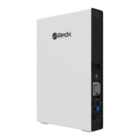
flamco FlexTherm Eco E3 User guide

Flamco B.V.
Amersfoortseweg 9
3751 LJ Bunschoten
the Netherlands
+31 33 299 75 00
info@flamco.nl
www.flamcogroup.com
Copyright Flamco B.V., Bunschoten, the Netherlands. No part of this publication may be reproduced or published in any way without explicit permission and mention of the source.
The data listed are solely applicable to Flamco products. Flamco B.V. shall accept no liability whatsoever for incorrect use, application or interpretation of the technical information.
Flamco B.V. reserves the right to make technical alterations.
18200_D_V1.0

Montage instructie & gebruikshandleiding 2
FlexTherm Eco
ENG Installation and operating instruction
NLD Montage- en gebruikshandleiding
DEU Montage- und Bedienungsanleitung
FRA Installation et mode d’emploi


We reserve the right to change designs and technical specifications of our products. 4
Content
1. Introduction 5
1.1 Advantages of FlexTherm Eco compact heat storage ................................................................................. 5
2. Technical Specifications 6
3. FlexTherm Eco_A2_ET Controller 8
3.1 Description.................................................................................................................................................... 8
3.2 PCB identification......................................................................................................................................... 8
3.3 Installer settings ........................................................................................................................................... 9
4. Design of cold and hot water supplies 10
4.1 General requirements ................................................................................................................................ 10
4.2 Water distribution network design............................................................................................................ 10
4.3 Hot water circuit including expansion vessel............................................................................................ 10
4.4 Hard water areas.........................................................................................................................................10
5. Installation Guide lines 10
5.1 General wiring recommendations............................................................................................................. 10
5.2 FlexTherm Eco E storage ............................................................................................................................ 11
6. Electrical wiring 11
6.1 Heat storage fitted with electric element.................................................................................................. 11
4
We reserve the right to change designs and technical specifications of our products.
ENG

Manual FlexTherm Eco
5
1. Introduction
The FlexTherm Eco range of advanced and compact heat storage use the Phase Change Materials (PCMs) to store heat for producing hot water
and for space heating in buildings. Flamco heat storage can be classified as primary thermal because the hot water is heated instantaneously
on demand by transferring heat from the PCM to the mains water flowing through it, and they function like buer vessels for space heating
applications.
The pipe connections and the construction of a FlexTherm Eco range of storage are shown in figure above. The phase change material (PCM)
and the heat exchangers are housed in a sealed enclosure called ‘The Cell’. Although the Cell is sealed, the pressure inside the Cell is around
the ambient atmospheric pressure i.e. about 1.0 bar absolute. The Cell is insulated using highly eicient vacuum insulation panels. The outer
case and hydraulic and electrical connections are designed so that multiple storage can either be stacked or positioned side by side and then
connected either in series or parallel.
The FlexTherm Eco range of heat storage have two independent hydraulic circuits and either or both can be used for charging or discharging
the heat storage. The heat is transferred between the PCM and the high power (HPC) and the low power (LPC) hydronic circuits by means of an
integrated heat exchanger inside the Cell.
The heat storage are fitted with temperature sensors for measuring the charge state and for controlling their operation when connected to the
controller. All standard models of the FlexTherm Eco range of heat storage are supplied with PCM58 which has a phase transition temperature
of 58 °C.
The heat storage models covered by this document are listed in table 1.1. This document does not complete cover sizing, selection,
configuration or design of the heating and hot water system in a building. It only covers installation and commissioning of the selected compact
heat storage and a few examples of dierent applications.
Table 1.1: FlexTherm Eco Range of heat storage
Generic range Description Models
FlexTherm Eco E These heat storage are heated by internal electric heating
elements only and therefore these heat storage are equivalent to
Direct vented or unvented hot water cylinders
FlexTherm Eco E3, FlexTherm Eco E6, FlexTherm
Eco E9
1.1 Advantages of FlexTherm Eco compact heat storage
1.1.1 FlexTherm Eco
The main benefits of the FlexTherm Eco, compact heat storage, compared with the traditional hot water cylinders and hot water only thermal
stores are:
a. The heat is stored in the Phase Change Material and therefore the stored water content in the storage is less than 11 Litres
and the hot water is heated instantaneously on demand. Therefore:
• Easy installation because of low expansion volume.
• The risks of legionella are significantly reduced.
b. Quicker and less costly installation.
c. No mandatory annual maintenance or inspection is required and therefore lower running costs.
d. Operational needs: Smaller space, typically 2 – 3 times smaller than the equivalent hot water cylinders and clean installation.

We reserve the right to change designs and technical specifications of our products. 6
2. Technical Specifications
The standard models of the Flamco compact heat storage are supplied with PCM58 and these heat storage can be used in combination with any
heat source which can run at flow temperature greater than 65 °C. The discharge temperature from these standard compact heat storage models
will be between 52 and 55 °C.
The overall dimensions and weights of the compact heat storage models in the FlexTherm Eco range are listed in table 2.1 and their technical
specification is listed in table 2.2. The pressure loss characteristics of the compact heat storage are tabulated in tables 2.3a, 2.3b, 2.3c.
Table 2.1. Overall dimensions and weights of FlexTherm Eco compact heat storage range
Overall dimensions [mm] Weight [1]
Width Depth Height [kg]
FlexTherm Eco 3E 360 570 445 70
FlexTherm Eco 6E 360 570 645 120
FlexTherm Eco 9E 360 570 880 170
[1] The PCM in standard heat storage has a phase transition temperature of 58 °C
Table 2.2: Technical specification of FlexTherm Eco heat storage range
Size 3 Size 6 Size 9
Storage capacity –
Standard storage with
PCM58 [1]
[kWh] 3.5 7.0 10.5
Water content – Low
power circuit (LPC) [3]
Water content – High
power circuit (HPC) [4]
[L]
[L]
1.30
2.24
2.36
4.48
3.46
6.76
Equivalent hot water
cylinder size [5]
[L] 71 142 212
V40, Volume of hot water
available at 40°C [6]
[L] 85 185 300
• Heat loss rate
• Heat loss rate
• ErP Rating class –
Hot water storage vessel
[kWh/24h]
[W]
[ - ]
0.449
18.7
A+
0.649
27.0
A+
0.738
30.7
A+
Recommended
maximum HW flow rate
[L/min] 6 15 20
Minimum cold water
supply pressure at inlet
to the heat storage
[bar]
[MPa]
1.00
0.10
1.50
0.15
1.50
0.15
Maximum working
pressure:
High power (HPC) and
Low power (LPC) circuits
[bar]
[MPa]
10.0
1.0
10.0
1.0
10.0
1.0
Pressure loss
characteristics
(See tables 2.3)
• KV Value for the Low
power circuit (LPC)
• KV Value for the High
power circuit (HPC)
[ - ]
[ - ]
1.623
2.871
1.255
2.356
1.066
1.951
ENG

Manual FlexTherm Eco
7
1) Storage operating as hot water heaters. Charged to 75 °C and then discharged using mains cold water at 10 °C until the hot water
outlet temperature dropped to 40 °C.
2) Storage operating as hot water heaters. Charged to 55 °C and then discharged using mains cold water at 10 °C until the hot water
outlet temperature dropped to 40 °C.
3) For FlexTherm Eco E type, the low power circuit (LPC) can be connected to external heat source e.g. a boiler.
4) For FlexTherm Eco compact heat storage, the high power circuit (HPC) is connected to the mains cold water supply for producing hot water.
5) Calculated from the storage capacity of the heat storage and assuming that the hot water cylinder thermostat is set at 60 °C, mains
cold water inlet temperature is at 10 °C and the stored energy utilisation factor of cylinder is 0.85.
6) Calculated from the storage capacity of the heat storage and assuming that the hot water outlet temperature is set at 40 °C, mains
cold water inlet temperature is at 10 °C and the stored energy utilisation factor of cylinder is 0.95.
7) To fully charge the heat storage, the source flow temperature should be set so that it does not start to cycle on its internal thermostat
and it should not be less than the value stated in table 4.2a. The storage will be fully charged when the storage return temperature is
about 5°C less than the heat source flow temperature.
8) Maximum constant heat source flow temperature when charging the heat storage.
9) Recommended setting for the hot water thermostatic blending valve.
10) Power supply to the heat storage/system controller via local 2-pole isolator.
11) Power supply for the standby electric heater vial local 2-pole isolator – Only for FlexTherm Eco E type of heat storage.
Table 2.3a: Pressure loss characteristic of FlexTherm Eco 3E storage
Flow rate Low power circuit (LPC) High power circuit (HPC) HPC & LPC Circuits in parallel
[l/s] [m3/h] [bar] [kPa] [bar] [kPa] [bar] [kPa]
0.10 0.360 0.049 4.920 0.016 1.572 0.006 0.640
0.20 0.720 0.197 19.680 0.063 6.289 0.026 2.560
0.30 1.080 0.443 44.280 0.142 14.151 0.058 5.760
0.40 1.440 0.787 78.721 0.252 25.157 0.102 10.240
Table 2.3b: Pressure loss characteristic of FlexTherm Eco 6E storage
Flow rate Low power circuit (LPC) High power circuit (HPC) HPC & LPC Circuits in parallel
[l/s] [m3/h] [bar] [kPa] [bar] [kPa] [bar] [kPa]
0.10 0.360 0.082 8.228 0.023 2.335 0.010 1.000
0.20 0.720 0.329 32.914 0.093 9.339 0.040 4.000
0.30 1.080 0.741 74.056 0.210 21.013 0.090 9.000
0.40 1.440 1.317 131.655 0.374 37.357 0.160 16.000
Table 2.3c: Pressure loss characteristic of FlexTherm Eco 9E storage
Flow rate Low power circuit (LPC) High power circuit (HPC) HPC & LPC Circuits in parallel
[l/s] [m3/h] [bar] [kPa] [bar] [kPa] [bar] [kPa]
0.10 0.360 0.114 11.405 0.034 3.405 0.014 1.424
0.20 0.720 0.456 45.620 0.136 13.619 0.057 5.695
0.30 1.080 1.026 102.644 0.306 30.643 0.128 12.814
0.40 1.440 1.825 182.478 0.545 54.477 0.228 22.781
Minimum heat source
flow temperature [7] [°C] 65 65 65
Maximum heat source
flow temperature [8]
[°C] 80 80 80
Hot water outlet
temperature at design
flow rate [9]
[°C] 50 - 55 50 - 55 50 - 55
Heat storage controller
• CC power supply rating
at 230V, AC, 50Hz [10]
• Electric heater supply
rating at 230V, AC, 50Hz
[11]
• Standby power
consumption – All
models
• Power rating of the
heater at 230V, AC, 50Hz
(‘e’ models only)
[A]
[A]
[W]
[W]
6
16
<1
2,800
6
16
<1
2,800
6
16
<1
2,800

We reserve the right to change designs and technical specifications of our products. 8
3. FlexTherm Eco_A2_ET Controller
3.1 Description
The FlexTherm Eco_A2_ET controller is housed in the unit. The controller parameters can be changed on-site.
The variants of the control boxes available to match the dierent heat storage types as described below.
Figure 3.1: Controller in FlexTherm Eco Units
Power
>50%
>100%
Heating
3.2 PCB identification
Location of the switches and LEDs is shown in the figure below. Wiring connections for remote control input are shown, using the 4-way plug in
connector.
Table 3.1: Controller connections
5V input/output 2 J1.6 (FV) Connect to GND for timed boost (user switch)
5V input/output 1 J1.7 (FT) Connect to GND to command element on (PV
inverter)
GND J1.8 (GND) Ground for i/o signals
Remote control input
Boost switch input
ENG

Manual FlexTherm Eco
9
Control PCB
Power relay
Blue
Yellow
Red
Green
Blue
Red
2 core
temperture probe
4 core
temperture probe
To main supply
230 ~ 16A
Manual reset overheat
thermostat Element 2.8 kW
3.3 settings
Options
Depending on the application, dierent options may be selected.
Holding switch SW1 down will show the current setting on the 4 LEDs. Holding this switch down for longer than 5 seconds will cause the LEDs
to cycle. Release switch SW1 when the wanted combination of LEDs is illuminated, and this choice will be stored.
Table 3.3: Controller options and explanation
LED # Option # Option description
Show/set by holding down SW1
Explanation
D4 4 Remote control Unit will only charge from electricity if the remote control input is active or boost
function is active.
D3 3 Maximum charge temperature
O=80 °C
On=65 °C
For electric heated units use 80 °C. For heat pumps and some gas boilers, use 65
°C.
D2 2 PV input
O = No eect
On = Always recharge
For use with PV diversion controllers, this option will enable charging again aer
very little heat has been used or lost
D1 1 Recharge level
O = Shallow discharge
On = Deep discharge
This is the threshold at which charging will be re-enabled due to water usage
aer the store was full. The default setting (shallow discharge) is suitable for most
applications.
Power
>50%
>100%
Heating

We reserve the right to change designs and technical specifications of our products. 10
4. Design of cold and hot water supplies
4.1 General requirements
a. Minimum dynamic mains water supply pressure = 1.5 bar
b. Maximum dynamic mains water supply pressure = 10.0 bar
c. Mains cold and hot water pipe sizes maximum 22mm copper or equivalent
d. Expansion vessel charge pressure (If fitted) = Incoming mains pressure (bar)
Note: Although the heat storage are designed for 10bar maximum working pressure, it is recommended that if the incoming mains pressure is
greater than 5bar, an approved pressure regulator set at 5.0bar should be fitted for comfort of the occupants.
4.2 Water distribution network design
a. The water distribution network should be sized and designed to comply with the requirements of the relevant sections of EN1717.
4.3 Hot water circuit including expansion vessel
A --> cold in HPC
B --> cold in LPC
C --> warm out (LPC)
D --> warm out (HPC)
4.4 Hard water areas
In hard water areas where mains water hardness can exceed 150 ppm Total Hardness, you must install a scale reducing device in the cold water
supply to the heat storage to reduce the rate of accumulation of limescale.
Wasserhärtgrad < 8,4 °dH
Hardheid water < 150 ppm
Classe de dureté de l‘eau < 15 °fH
5. Installation Guide lines
5.1 General
a) The heat storage must be earthed.
b) The point of connection to the mains should be readily accessible and adjacent to the heat storage installation.
c) See for general installation “Quick start guide “ FlexTherm Eco
d) Every FlexTherm Eco E unit is equipped with an automatic fuse to protect the heating element for overheating.
ENG

Installation and operating instruction
11 Manual FlexTherm Eco
11
Figure 5.1: FlexTherm Eco direct electrically heated battery
b
l
l
5.2 FlexTherm Eco E storage
5.2.1 Mains cold water and hot water supplies
The FlexTherm Eco E storage are designed for producing hot water in dwellings and are heated directly by electricity. Therefore, these heat
storage are equivalent to direct electrically heated hot water cylinders. The general requirements for designing hot water network are given in
section 4 of this document.
a. Pipe connections – All model in this range: 22mm copper.
b. Both heat exchangers must be connected and filled with water during the application, see also section 4.
c. For minimum and maximum working pressures see technical section and section 4.1.
6. Electrical wiring
6.1 Heat storage fitted with electric element
The heat storage will be supplied with a FlexTherm Eco_A2_ET internal control box.
Please contact Flamco if your application is not covered and you are not sure how to proceed.
Mains supply – Electric storage water heater
Run and connect mains power supply cable (16A, minimum 2.5mm2 CSA) from the local 2-pole isolator to the heat storage controller as
shown in figure 6.1.
• Brown (Live): Terminal 4 and Terminal 1 (Live)
• Blue (Neutral): Terminal 5 and Terminal 2 (Neutral)
• Green/Yellow (Earth): Terminal 6 (Earth)
Figure 6.1: Wiring for electric storage water heater applications
16 Amp
230 V

12
We reserve the right to change designs and technical specifications of our products.
Installatie- en bedieningshandleiding
1. Inleiding 13
1.1 Voordelen van de FlexTherm Eco compacte warmteopslag .................................................................... 13
2. Technische specificaties 14
3. FlexTherm Eco_A2_ET regelaar 16
3.1 Beschrijving ................................................................................................................................................ 16
3.2 PCB-identificatie......................................................................................................................................... 16
3.3 Installateur-instellingen ............................................................................................................................. 17
4. Ontwerp van de koud- en warmwatervoorziening 18
4.1 Algemene eisen........................................................................................................................................... 18
4.2 Ontwerp van het waterleidingnet.............................................................................................................. 18
4.3 Warmwatercircuit inclusief expansievat ................................................................................................... 18
4.4 Gebieden met hard water .......................................................................................................................... 18
5. Installatierichtlijnen 18
5.1 Algemeen .................................................................................................................................................... 19
5.2 FlexTherm Eco E opslag..............................................................................................................................19
6. Elektrische bedrading 19
6.1 Warmteopslag voorzien van elektrisch element....................................................................................... 19
We reserve the right to change designs and technical specifications of our products. 12
NLD

Manual FlexTherm Eco
13 Manual FlexTherm Eco
13
1. Inleiding
De FlexTherm Eco serie van geavanceerde en compacte warmteopslag gebruikt Phase Change Materials (PCM's) om warmte op te slaan
voor het produceren van warm water en voor de verwarming van gebouwen. Flamco warmteopslag kan worden geclassificeerd als primair
thermisch omdat het warme water op verzoek onmiddellijk wordt verwarmd door de warmte van de PCM over te brengen naar het
leidingwater dat er doorheen stroomt, en ze functioneren als buervaten voor verwarmingstoepassingen.
De leidingaansluitingen en de constructie van een FlexTherm Eco opslagsysteem zijn in de bovenstaande afbeelding weergegeven.
Het zogenoemde Phase Change Material (PCM, faseveranderingsmateriaal) en de warmtewisselaars zijn ondergebracht in een gesloten
behuizing genaamd 'de cel'. Hoewel de cel is afgesloten, ligt de druk in de cel rond de atmosferische omgevingsdruk, d.w.z. ongeveer 1,0
bar absoluut. De cel is geïsoleerd met zeer eiciënte vacuümisolatiepanelen. De buitenste behuizing en de hydraulische en elektrische
aansluitingen zijn zo ontworpen dat meerdere opslagen kunnen worden gestapeld of naast elkaar kunnen worden geplaatst en vervolgens
in serie of parallel kunnen worden geschakeld.
De FlexTherm Eco-serie warmteopslag hee twee onafhankelijke hydraulische circuits en kan worden gebruikt voor het laden of ontladen
van de warmteopslag. De warmte wordt overgedragen tussen de PCM en de hydronische circuits met hoog vermogen (HPC) en laag
vermogen (LPC) door middel van een geïntegreerde warmtewisselaar in de cel.
De warmteopslag is uitgerust met temperatuursensoren voor het meten van de laadtoestand en voor het regelen van de werking ervan bij
aansluiting op de regelaar. Alle standaardmodellen van de FlexTherm Eco-serie warmteopslag worden geleverd met PCM58, die een fase-
overgangstemperatuur van 58 °C hee.
De warmteopslagmodellen waarop dit document betrekking hee, staan vermeld in tabel 1.1. Dit document gee geen volledige
beschrijving van de dimensionering, selectie, configuratie of het ontwerp van de verwarmings- en warmwaterinstallatie in een gebouw.
Het omvat alleen de installatie en inbedrijfstelling van de geselecteerde compacte warmteopslag en enkele voorbeelden van verschillende
toepassingen.
Tabel 1.1: FlexTherm Eco-serie warmteopslag
Algemene serie Beschrijving Modellen
FlexTherm Eco E Deze warmteopslag wordt alleen verwarmd door interne
elektrische verwarmingselementen en daarom is deze
warmteopslag gelijk aan direct geventileerde of niet
geventileerde warmwaterboilers
FlexTherm Eco E3, FlexTherm Eco E6,
FlexTherm Eco E9
1.1 Voordelen van de FlexTherm Eco compacte warmteopslag
1.1.1 FlexTherm Eco
De belangrijkste voordelen van de FlexTherm Eco, compacte warmteopslag, in vergelijking met de traditionele warmwaterboilers en
warmwateropslag zijn:
a. De warmte wordt opgeslagen in het Phase Change Material en daardoor is het opgeslagen watervolume in de opslag minder dan 11 liter
en wordt het warme water op verzoek direct verwarmd. Dit leidt tot:
• Eenvoudige installatie door het geringe expansievolume.
• De risico's van legionella worden aanzienlijk verminderd.
b. Snellere en goedkopere installatie.
c. Er is geen verplicht jaarlijks onderhoud of inspectie nodig en dus lagere bedrijfskosten.
d. Operationele behoeen: Kleinere ruimte, meestal 2 tot 3 keer kleiner dan de equivalente warmwatercilinders en schone installatie.

14
We reserve the right to change designs and technical specifications of our products.
2. Technische specificaties
De standaard modellen van de Flamco compacte warmteopslag worden geleverd met PCM58 en deze warmteopslag kan worden gebruikt in
combinatie met elke warmtebron die bij een aanvoertemperatuur van meer dan 65 °C kan werken. De uitvoertemperatuur van deze standaard
compacte warmteopslagmodellen ligt tussen de 52 en 55 °C.
De totale afmetingen en gewichten van de compacte warmteopslagmodellen van de FlexTherm Eco-serie worden vermeld in tabel 2.1 en hun
technische specificaties staan in tabel 2.2. De drukverlieseigenschappen van de compacte warmteopslag zijn in de tabellen 2.3a, 2.3b en 2.3c in
tabelvorm weergegeven.
Table 2.1. Afmetingen en gewichten van het programma FlexTherm Eco compacte warmteopslag
Totale afmetingen [mm] Gewicht [1]
Breedte Diepte Hoogte [kg]
FlexTherm Eco 3E 360 570 445 70
FlexTherm Eco 6E 360 570 645 120
FlexTherm Eco 9E 360 570 880 170
[1] De PCM in standaard warmteopslag hee een fase-overgangstemperatuur van 58 °C
Tabel 2.2: Technische specificatie van de serie FlexTherm Eco warmteopslag
Grootte 3 Grootte 6 Grootte 9
Opslagcapaciteit -
Standaardopslag met
PCM58 [1]
[kWh] 3,5 7,0 10,5
Watervolume - circuit
met laag vermogen
(LPC) [3]
Watervolume - circuit
met hoog vermogen
(HPC) [4]
[L]
[L]
1,30
2,24
2,36
4,48
3,46
6,76
Gelijkwaardige grootte
van de warmwaterboiler
[5]
[L] 71 142 212
V40, Volume van warm
water beschikbaar bij
40°C [6]
[L] 85 185 300
• Warmteverlies
• Warmteverlies
• ErP
classificatieklasse -
Warmwateropslagvat
[kWh/24h]
[W]
[ - ]
0,449
18,7
A+
0,649
27,0
A+
0,738
30,7
A+
Aanbevolen maximale
HW-doorstroomsnelheid
[L/min] 6 15 20
Minimale
koudwatertoevoerdruk
bij de inlaat van de
warmteopslag
[bar]
[MPa]
1,00
0,10
1,50
0,15
1,50
0,15
Maximale operationele
druk:
Circuits met hoog
vermogen (HPC) en laag
vermogen (LPC)
[bar]
[MPa]
10,0
1,0
10,0
1,0
10,0
1,0
Kenmerken van het
drukverlies
(zie tabel 2.3)
•
KV-waarde voor het laag
vermogen circuit (LPC)
•
KV-waarde voor het hoog
vermogen circuit (HPC)
[ - ]
[ - ]
1.623
2.871
1.255
2.356
1.066
1.951
NLD

Manual FlexTherm Eco
15 Manual FlexTherm Eco
15
1) Opslag die als warmwaterverwarming werkt. Opgeladen tot 75 °C en vervolgens geloosd m.b.v. koud leidingwater van 10 °C tot de
uitvoertemperatuur van het warme water tot 40 °C is gedaald.
2) Opslag die als warmwaterverwarming werkt. Opgeladen tot 55 °C en vervolgens geloosd m.b.v. koud leidingwater van 10 °C tot de
uitvoertemperatuur van het warme water tot 40 °C is gedaald.
3) Bij het type FlexTherm Eco E kan het circuit met laag vermogen (LPC) op een externe warmtebron, bijv. een ketel, worden aangesloten.
4) Voor de compacte warmteopslag FlexTherm Eco wordt het circuit met hoog vermogen (HPC) aangesloten op de koudwaterleiding
voor het produceren van warm water.
5) Berekend op basis van de opslagcapaciteit van de warmteopslag en ervan uitgaande dat de warmwaterboilerthermostaat op 60 °C is
ingesteld, de koudwatertoevoertemperatuur van het leidingwater op 10 °C en de opgeslagen energiebenuttingsfactor van de boiler 0,85 is.
6)
Berekend op basis van de opslagcapaciteit van de warmteopslag en ervan uitgaande dat de uitvoertemperatuur van het warme water op 40 °C is
ingesteld, de koudwatertoevoertemperatuur van het leidingwater op 10 °C en de opgeslagen energiebenuttingsfactor van de boiler 0,95 is.
7) Om de warmteopslag volledig op te laden, moet de aanvoertemperatuur van de bron zo worden ingesteld dat de warmteopslag niet op de
interne thermostaat begint te draaien en mag de temperatuur niet lager zijn dan de in tabel 4.2a vermelde waarde. De opslag is volledig
opgeladen wanneer de retourtemperatuur van de opslag ongeveer 5°C lager is dan de aanvoertemperatuur van de warmtebron.
8) Maximale constante aanvoertemperatuur van de warmtebron bij het laden van de warmteopslag.
9) Aanbevolen instelling voor de thermostatische mengkraan voor het warme water.
10) Stroomtoevoer naar de warmteopslag/systeem-controller via een lokale 2-polige isolator.
11) Stroomvoorziening voor de elektrische verwarming via de lokale 2-polige isolator - Alleen voor FlexTherm Eco E-warmteopslag.
Tabel 2.3a: Kenmerken van het drukverlies bij FlexTherm Eco 3E-opslag
Doorstroomsnelheid Circuit met laag vermogen
(LPC)
Circuit met hoog vermogen
(HPC)
Parallelle HPC- en LPC-circuits
[l/s] [m3/h] [bar] [kPa] [bar] [kPa] [bar] [kPa]
0,10 0,360 0,049 4,920 0,016 1,572 0,006 0,640
0,20 0,720 0,197 19,680 0,063 6,289 0,026 2,560
0,30 1,080 0,443 44,280 0,142 14,151 0,058 5,760
0,40 1,440 0,787 78,721 0,252 25,157 0,102 10,240
Tabel 2.3b: Kenmerken van het drukverlies bij FlexTherm Eco 6E-opslag
Doorstroomsnelheid Circuit met laag vermogen
(LPC)
Circuit met hoog vermogen
(HPC)
Parallelle HPC- en LPC-circuits
[l/s] [m3/h] [bar] [kPa] [bar] [kPa] [bar] [kPa]
0,10 0,360 0,082 8,228 0,023 2,335 0,010 1,000
0,20 0,720 0,329 32,914 0,093 9,339 0,040 4,000
0,30 1,080 0,741 74,056 0,210 21,013 0,090 9,000
0,40 1,440 1,317 131,655 0,374 37,357 0,160 16,000
Tabel 2.3c: Kenmerken van het drukverlies bij FlexTherm Eco 9E-opslag
Doorstroomsnelheid Circuit met laag vermogen
(LPC)
Circuit met hoog vermogen
(HPC)
Parallelle HPC- en LPC-circuits
[l/s] [m3/h] [bar] [kPa] [bar] [kPa] [bar] [kPa]
0,10 0,360 0,114 11,405 0,034 3,405 0,014 1,424
0,20 0,720 0,456 45,620 0,136 13,619 0,057 5,695
0,30 1,080 1,026 102,644 0,306 30,643 0,128 12,814
0,40 1,440 1,825 182,478 0,545 54,477 0,228 22,781
Minimale
aanvoertemperatuur
van de warmtebron [7]
[°C] 65 65 65
Maximale
aanvoertemperatuur
van de warmtebron [8]
[°C] 80 80 80
Uitvoertemperatuur
warm water bij beoogde
doorstroomsnelheid [9]
[°C] 50 - 55 50 - 55 50 - 55
Warmteopslag-regelaar
• CC-voedingsspanning
bij 230V, AC, 50Hz [10]
• Voedingsspanning
elektrische verwarming
op 230V, AC, 50Hz [11]
• Stand-by
stroomverbruik - Alle
modellen
• Vermogen van de
verwarming op 230V,
AC, 50Hz (alleen 'e'
modellen)
[A]
[A]
[W]
[W]
6
16
<1
2,800
6
16
<1
2,800
6
16
<1
2,800

16
We reserve the right to change designs and technical specifications of our products.
3. FlexTherm Eco_A2_ET regelaar
3.1 Beschrijving
De FlexTherm Eco_A2_ET-regelaar bevindt zich in het apparaat. De regelaarparameters kunnen ter plaatse worden gewijzigd.
De beschikbare varianten van de regelkasten zijn afgestemd op de verschillende typen warmteopslag, zoals hieronder beschreven.
Afbeelding 3.1: Regelaar in FlexTherm Eco-eenheden
Vermogen
>50%
>100%
Verwarming
3.2 PCB-identificatie
De plaats van de schakelaars en LED's is weergegeven in de onderstaande afbeelding. De bedradingsaansluitingen voor de ingang van de
afstandsbediening worden weergegeven met behulp van de 4-wegconnector
Tabel 3.1: Regelaar-aansluitingen
5V invoer/uitvoer 2 J1.6 (FV) Verbinding maken met GND voor een tijdelijke
boost (gebruikersschakelaar)
5V invoer/uitvoer 1 J1.7 (FT) Aansluiten op GND om het besturingselement
aan te sturen (PV-omvormer)
GND J1.8 (GND) Massa voor ingaande/uitgaande signalen
Ingang voor afstandsbediening
Ingang voor boost-schakelaar
NLD

Manual FlexTherm Eco
17 Manual FlexTherm Eco
17
3.3 Installateur-instellingen
Opties
Afhankelijk van de toepassing kunnen er verschillende opties worden geselecteerd.
Houd de schakelaar SW1 ingedrukt om de huidige instelling op de 4 LED's weer te geven. Als u deze schakelaar langer dan 5 seconden
ingedrukt houdt, zullen de LED's gaan knipperen. Laat de schakelaar SW1 los zodra de gewenste combinatie van LED's brandt; deze keuze
wordt opgeslagen.
Tabel 3.3: Regelaar-opties en uitleg
LED # Optie # Beschrijving van de optie
Weergeven/instellen door SW1
ingedrukt te houden
Toelichting
D4 4 Afstandsbediening Het apparaat laadt alleen op van elektriciteit als de ingang van de
afstandsbediening actief is of als de boost-functie actief is.
D3 3 Maximale laadtemperatuur
Uit=80 °C
Aan=65 °C
Voor elektrisch verwarmde apparaten 80 °C gebruiken. Gebruik voor
warmtepompen en sommige gasketels 65 °C.
D2 2 PV-ingang
Uit = geen eect
Aan = altijd opladen
Bij gebruik met PV-omleidingsregelaars maakt deze optie het mogelijk om na zeer
weinig gebruik of verlies van warmte weer op te laden
D1 1 Oplaadniveau
Uit = Oppervlakkige ontlading
Aan = Diepe ontlading
Dit is de drempel waarna het opladen weer wordt ingeschakeld vanwege het
waterverbruik nadat de opslag vol was. De standaardinstelling (oppervlakkige
ontlading) is geschikt voor de meeste toepassingen.
Vermogen
>50%
>100%
Verwarming
Controle PCB
Vermogensrelais
Blauw
Geel
Rood
Groen
Blauw
Rood
Temperatuursonde
met 2 kernen
Temperatuursonde
met 4 kernen
Naar
stroomvoorziening
230 ~ 16A
Handmatige reset
oververhittingsthermostaat Element 2.8 kW

18
We reserve the right to change designs and technical specifications of our products.
4. Ontwerp van de koud- en warmwatervoorziening
4.1 Algemene eisen
a. Minimale dynamische netdruk van de drinkwatervoorziening = 1,5 bar
b. Maximale dynamische netdruk van de drinkwatervoorziening = 10,0 bar
c. Koud- en warmwaterleidingen met een maximale diameter van 22 mm (koper of een equivalent)
d. Laaddruk expansievat (indien aanwezig) = inkomende netdruk (bar)
Let op: Hoewel de warmteopslag is ontworpen voor een maximale operationele druk van 10 bar, wordt aanbevolen om bij een inkomende
netdruk van meer dan 5 bar een goedgekeurde drukregelaar te monteren die is ingesteld op 5,0 bar voor het comfort van de bewoners.
4.2 Ontwerp van het waterleidingnet
a. Het waterleidingnet moet zodanig zijn gedimensioneerd en ontworpen dat het voldoet aan de eisen van de relevante paragrafen van EN171717.
4.3 Warmwatercircuit inclusief expansievat
A --> koud in HPC
B --> koud in LPC
C --> warm uit (LPC)
D --> warm uit (HPC)
4.4 Gebieden met hard water
In gebieden met hard water waar de hardheid van het leidingwater meer dan 150 ppm kan bedragen, moet u een kalkreducerende
voorziening in de koudwatertoevoer naar de warmteopslag installeren om kalkaanslag te verminderen.
Wasserhärtgrad <8,4 °dH
Hardheid water < 150 ppm
Classe de dureté de l'eau <15 °fH
5. Installatierichtlijnen
5.1 Algemeen
a) De warmteopslag moet geaard zijn.
b) Het aansluitpunt op het elektriciteitsnet moet gemakkelijk toegankelijk zijn en zich naast de warmteopslaginstallatie bevinden.
c) Zie voor de algemene installatie „Quick Start Guide“ FlexTherm Eco
d) Elke FlexTherm Eco E is uitgerust met een automatische zekering om het verwarmingselement tegen oververhitting te beschermen.
NLD

Installation and operating instruction
19 Montage- en gebruikshandleiding
19 Manual FlexTherm Eco
19
Afbeelding 5.1: FlexTherm Eco direct elektrisch verwarmde batterij
b
l
l
Over-
verhittings
thermostaat
5.2 FlexTherm Eco E opslag
5.2.1 Netleidingen voor koud en warm water
De FlexTherm Eco E opslag is ontworpen voor de productie van warm water in woningen en wordt direct verwarmd door middel van
elektriciteit. Deze warmteopslag is daarom gelijkwaardig aan directe elektrisch verwarmde warmwaterboilers. De algemene eisen voor het
ontwerp van het warmwaternetwerk worden in paragraaf 4 van dit document gegeven.
a. Leidingaansluitingen - Alle modellen uit deze serie: 22mm koper.
b. Beide warmtewisselaars moeten tijdens de toepassing worden aangesloten en met water worden gevuld, zie ook paragraaf 4.
c. Voor de minimale en maximale operationele druk zie het technische gedeelte en punt 4.1.
6. Elektrische bedrading
6.1 Warmteopslag voorzien van elektrisch element
De warmteopslag wordt geleverd met een FlexTherm Eco_A2_ET interne controlebox.
Neem contact op met Flamco als uw toepassing niet wordt vermeld en u niet zeker weet hoe u verder moet gaan.
Stroomvoorziening - Elektrische warmwaterbolier
Voer de netvoedingskabel (16A, minimaal 2,5mm2 CSA) van de lokale 2-polige isolator naar de warmteopslag-regelaar (zie afbeelding 6.1)
en sluit hem aan.
• Bruin (Live): Terminal 4 en Terminal 1 (Live)
• Blauw (Neutraal): Terminal 5 en Terminal 2 (Neutraal)
• Groen/geel (Aarde): Terminal 6 (Aarde)
Afbeelding 6.1: Bedrading voor elektrische warmwaterboilers
16 Amp
230 V

20
We reserve the right to change designs and technical specifications of our products.
Installations- und Betriebsanleitung
1. Einleitung 21
1.1 Vorteile des Kompakt-Wärmespeichers FlexTherm Eco........................................................................... 21
2. Technische Daten 22
3. FlexTherm Eco_A2_ET Steuerung 24
3.1 Beschreibung.............................................................................................................................................. 24
3.2 Übersicht über die PCB .............................................................................................................................. 24
3.3 Installateur-Einstellungen.......................................................................................................................... 25
4. Auslegung der Kalt- und Warmwasserzuleitungen 26
4.1 Allgemeine Anforderungen ........................................................................................................................ 26
4.2 Auslegung des Wasserverteilungsnetzes .................................................................................................. 26
4.3 Warmwasserkreis einschließlich Ausdehnungsgefäß .............................................................................. 26
4.4 Regionen mit hartem Wasser..................................................................................................................... 26
5. Installationshinweise 26
5.1 Allgemeines................................................................................................................................................. 27
5.2 FlexTherm Eco E Wärmespeicher............................................................................................................... 27
6. Elektrische Verkdrahtung 27
6.1 Wärmespeicher mit elektrischem Element............................................................................................... 27
20
We reserve the right to change designs and technical specifications of our products.
DEU
This manual suits for next models
3
Table of contents
Languages:
Popular Storage manuals by other brands
Panasonic
Panasonic WJHDE300 - DIGITAL DISK RECORDER Service manual
HP
HP C7745NB - SureStore DLT Tape Autoloader 1/9 manual

Western Digital
Western Digital WDBALG5000ABK Specifications
Maxtor
Maxtor DiamondMax Plus9 60GB AT product manual
Western Digital
Western Digital Ultrastar Data102 Configurations
IBM
IBM 4146 T30 manual
