Flame mQMCV User manual

µQMCV MIDI to CV interface
MANUAL
Version 1.00
FLAME

Manual FLAME QMCV Version 1.00
2
Contents
1. Short description................................................................ 3
2. Hardware / connections...................................................... 3
2.1 Connection to the modular system (Doepfer bus) 3
2.2 Module overview 4
2.3 MIDI connections 5
3. Handling ........................................................................... 6
3.1 Quad MIDI to CV interface 6
3.2 Multimode 7
3.3 Modulation / Pitchbend outputs 8
3.4 RUN / 1/16th outputs8
3.5 Settings via SYSEX files 9
3.6 SYSEX data format 10
4. Appendix and technical informations .............................. 12
4.1 Technical details
4.2 Warrenty
4.3 Terms of production
4.4 Disposal
4.5 Support
4.6 Acknowledgment

1. Short description
2. Hardware / connections
The "µQMCV" module is a compact up to 4 voice MIDI-to-CV interface with additional CV out-
puts for modulation and pitch bend, as well as two MIDI clock outputs for RUN and 16th clock.
The range of notes is 8 octaves. The MIDI interface is multi-mode capable, which means that
the individual voices can be used separately on different MIDI channels in defined modes in
groups. For example, voices 1-3 can be used in three voices on one midi channel and the
remaining fourth voice can be used monophonically on another midi channel. The module uses
the “Round Robin” algorythm for polyphonic voice assignment.
The module is programmable via LEARN function with a MIDI keyboard or via SYSEX data (via
computer). Some SYSEX files with default settings already exist.
The module has two MIDI sockets (mini jacks in TRS-B standard) INPUT and THRU. The data
received at MIDI-IN is forwarded via MIDI-THRU. Additional MIDI modules can then be con-
nected there.
3
2.1 Connection to the euro rack modular system (Doepfer bus)
The module is delivered with a connected
ribbon cable for the Doepfer bus. The red
lead marks -12 volt. Connecting the module
please note the right polarity!
If the module is poled accidentally wrong
safety diodes avoid the immediate destruc-
tion of the module but further damages can-
not be excepted.
So please pay attention: Check the con-
nection various times before switching on!
The current consumption of the module is on
average +70mA.
CAUTION!
Do not accidentally connect the MIDI THRU
output to high CV voltages! This can possibly
damage the hardware!
-12V
Ground
Ground
Ground
+12V

4
2.2 Module overview
u
|}
x
y
{
v
w
~
~
z
LEARN button
Gate Note/Velocity CV outputs voice 1
Gate Note/Velocity CV outputs voice 2
Gate Note/Velocity CV outputs voice 3
Gate Note/Velocity CV outputs voice 4
MIDI Clock RUN output
1/16th MIDI Clock output
MIDI Input (MIDI TRS-B Standard)
MIDI THRU Output (MIDI TRS-B Standard)
CV outputs Modulation and Pitchbend
u
w
v
x
y
{
z
|
}
~

KEYBOARD/CONTROLLER
2.3 MIDI connections
The module has two MIDI sockets (TRS-B standard mini jacks) INPUT and THRU. Connect the MIDI
input to the MIDI output of your keyboard / controller or computer. The data received at MIDI-IN is
forwarded via MIDI-THRU. Acorresponding commercially available adapter (MIDI-DIN to Mini TRS-
B) or a 3.5mm (1/8 inch) stereo jack cable is used for the MIDI connection.
Examples of possible connections:
Forwarding the MIDI data via
THRU to other MIDI modules
5
3,5mm (1/8 inch) mini jack
stereo cabel
COMPUTER
Adaptor schemata
MIDI DIN jack to
3,5mm (1/8 inch) mini jack
MIDI TRS-B standard

6
3. Handling
The module is preset as a four-way MIDI-to-CV interface on midi channel 1. The two controllers
MODULATION and PITCHBEND also work on this midi channel. Send notes from a connected
MIDI keyboard over an 8 octave range of note numbers 12-108. The module can output the
GATE and CV voltages for up to 4 notes at the same time. The “Round Robin” algorythm is used.
If more than 4 notes are pressed at the same time, the last played note replaces the first play-
ed note.
Classic standard connection in the modular system:
Connect the GATE output of a voice to the GATE input of an ADSR generator, the NOTE output
to the 1V / octave input of a VCO and the VELOCITY output to the CV input of a VCA. You need
this four times for all voices.
The CV output MODULATION can be used for filter modulation and the PITCHBEND output for
pitch changes of the VCOs.
How to change the MIDI channel:
Press the LEARN button once (until it flashes). Then send 4 notes in succession on the same
desired midi channel (the GATE LEDs light up in succession when they are received). After
receiving the fourth note, the LEARN function ends automatically (LEARN key stops flashing).
The new midi channel is saved permanently. This now also applies to the two CV outputs
MODULATION and PITCHBEND.
3.1 Quad MIDI-to-CV Interface
MIDI KEYBOARD
to the GATE-IN ADSR (0/+5v)
to the 1V/oct input VCO (0..+8v)
to the CV input VCA (0..+5v)
CV MODULATION (0..+5v)
CV PITCHBEND (0..+2v)

7
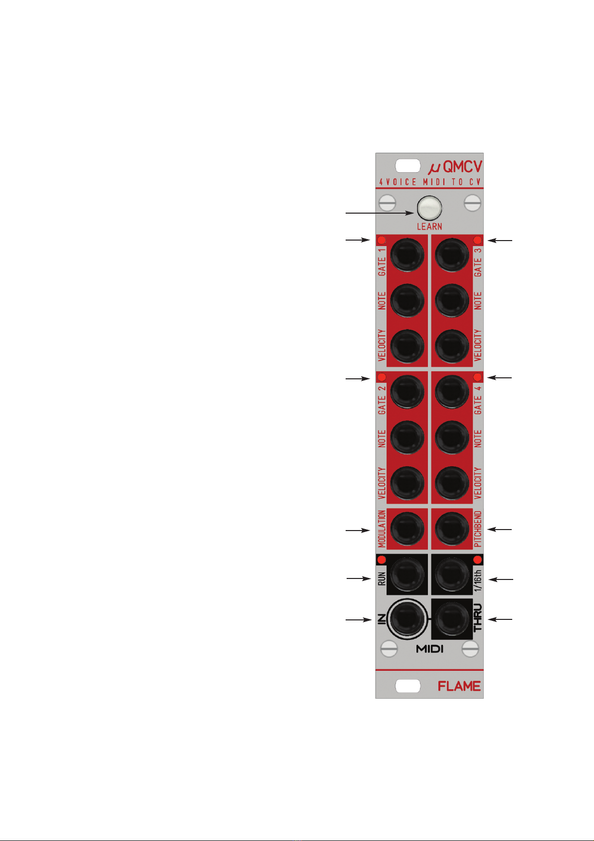
The four voices of the module (each with GATE / NOTE / VELOCITY outputs) can also be used
separately in other defined groups. To do this, the voices must be assigned to other midi chan-
nels. There are 5 modes that can be set with the LEARN function (or via SYSEX):
Aquad polyphon (all same midi channel) -> see also chapter 3.1
BVoices 1-3 polyphonic and voice 4 monophonic (2 different midi channels)
CVoices 1 + 2 duophones and voices 3 + 4 duophones (2 different midi channels)
DVoices 1 + 2 duophones, voices 3 and 4 monophonic (3 different midi channels)
EVoices 1-4 monophonic (all different midi channels)
Note: The voices of the module can only be used in these 5 combinations. So it is not possible
eg. use voice 1 monophone and voice 2-4 in three voices!
How to change the MODE with LEARN:
Press the LEARN button once (until it flashes). Then send 4 notes in succession on the desired
midi channels in the correct order, as mentioned above in point A-E (the GATE LEDs light up in
succession when they are received). The corresponding mode is automatically recognized by
the module. After receiving the fourth note, the LEARN function ends automatically (LEARN key
stops flashing). The new midi channels (and thus the Mode) are saved permanently.
Caution: If the midi channels of the sent notes were sent in the wrong order, the LEARN mode
is aborted with the LED flashing twice. The old settings are retained!
Note: To simplify the operation of the LEARN function, the midi channel of the first voice is auto-
matically assigned to the two CV outputs MODULATION and PITCHBEND. However, it is pos-
sible to set the midi channel of these two CV outputs individually via SYSEX.
Example 1:
With LEARN, send a note twice on midi channel 1, then a third note on midi channel 2 and a
fourth note on midi channel 16. The module recognizes Mode D with the following settings:
- Voices 1 + 2 duphone on midi channel 1
- Voice 3 monophonic on midi channel 2
- Voice 4 monophonic on midi channel 16
- CV outputs modulation and pitch bend on midi channel 1
Example 2:
With LEARN, send a note on midi channel 3 three times and then the fourth note on midi chan-
nel 10. The module uses this to recognize mode B with the following settings:
- Voices 1-3 three-part polyphonic on midi channel 3
- Voice 4 monophonic on midi channel 10
- CV outputs modulation and pitch bend on midi channel 3
3.2 MULTIMODE

8
The module has two additional CV outputs:
The CV output MODULATION reacts to MODWHEEL (Control Change No. 1) and supplies a
voltage of 0 .. + 5V
The CV output PITCHBEND reacts to the pitch bend wheel and supplies a voltage of 0 .. + 2v.
After switching on, the voltage is set to + 1v (middle position of the pitch bend wheel). If the pitch
bend wheel is turned down, the voltage drops to zero volts, if it is turned up, the voltage rises to
a maximum of + 2v. The module only evaluates the MSB data byte (since most pitch benders
do not use the high resolution).
Midi channel setting:
Normally, the two CV outputs are automatically assigned to the midi channel of the first voice.
However, you can also change the midi channel for both individually using the SYSEX file.
-> see chapter SYSEX
CONTROL CHANGE number setting:
The CV output MODULATION is set to control change number 1. This number can also be chan-
ged using SYSEX.
-> see chapter SYSEX
3.3 MODULATION / PITCHBEND CV outputs
The module has two additional clock / gate outputs:
The GATE output RUN is switched on when a MIDI STARTor CONTINUE command is recei-
ved and switched off when a MIDI STOP is received.
The clock output 1/16th delivers 16th clock impulses which are generated from the received
MIDI clock. The impulses have a duty cycle of 50% (32nd note length). The clock is only output
after receiving MIDI STARTor CONTINUE.
Both outputs deliver approximately + 5v in the ON state.
3.4 RUN and 1/16th outputs

As an alternative to the LEARN function, the module can also be programmed via SYSEX.
Some SYSEX files are available for this. These can be loaded with a MIDI SYSEX dump pro-
gram (e.g. MIDI-OX or Elektron C6) from a computer via MIDI. After receiving the SYSEX file,
the data is saved permanently.
NOTE:
When the SYSEX data is received, the LEARN LED lights up permanently and goes out when
reception is successful. If the SYSEX reception was faulty, the LED flashes several times in
quick succession, it is then not saved and the old data are retained. The reception can also be
canceled with the LEARN key.
DETAILS:
There are three types of files:
Type 1: change all data
Type 2: set midi channel and control change number from the MODULATION output
Type 3: set midi channel from the PITCHBEND output
You can download some ready-made SYSEX files from the FLAME website.
You can also create your own SYSEX files (for example with the freeware program MIDI-OX).
An overview and documentation of the implemented SYSEX data formats can be found in the
next chapter.
3.5 Settings via SYSEX files
9

10
3.6 SYSEX Data format
The assignment of the MIDI data for the voices (and thus the multimodes 1-5) and for the two
controller outputs (modulation and pitch bend) can be done with the help of SYSEX data. The
module understands different types of SYSEX files:
Typ 1: SYX file for all data
Typ 2: SYX file for setting the control change number and the
midi channel from CV output modulation
11110000 F0 Exclusive Status
01111101 7D Header Flame module
000010110C Flame module “µQMCV”
00000001 01 version 1
00000110 06 data type 1 (dump all data)
0000xxxx nch1 4 data bytes MIDI channels for voices 1-4
| | (range: 00=channel 1 .. 0F=channel 16)
0000xxxx nch4
0xxxxxxx ccnr 1 data byte control change number of Modulation output
(range: 00=CCnr 0 .. 7F=CCnr 127)
0000xxxx ccch 1 data byte MIDI channel of Modulation output
0000xxxx pbch 1 data byte MIDI channel of Pitchbend output
(range: 00=channel 1 .. 0F=channel 16)
11110111 F7 End of Exclusive
(total 13 bytes)
11110000 F0 Exclusive Status
01111101 7D Header
000010110C Flame module “µQMCV”
00000001 01 version 1
00000111 07 data type 2 (dump data Modulation output)
0xxxxxxx ccnr 1 data byte control change number of Modulation output
(range: 00=CCnr 0 .. 7F=CCnr 127)
0000xxxx ccch 1 data byte MIDI channel of Modulation output
(range: 00=channel 1 .. 0F=channel 16)
11110111 F7 End of Exclusive
(total 8 bytes)

11
Typ 3: SYX file for setting the midi channel from the CV output pitch bend
11110000 F0 Exclusive Status
01111101 7D Header
000010110C Flame module “µQMCV”
00000001 01 version 1
00000111 08 data type 3 (dump midi channel pitchbend output)
0000xxxx pbch 1 data byte MIDI channel of Pitchbend output
(range: 00=channel 1 .. 0F=channel 16)
11110111 F7 End of Exclusive
(total 7 bytes)

12
4. Appendix
4.1. Technical details
Connections:
Ribbon cable adapter for Doepfer bus +/-12Volt
Inputs: 1x MIDI (TRS-B standard) 1/8th inch stereo jack
Outputs: 1x MIDI (TRS-B standard) 1/8th inch stereo jack
4x CV 0..+8V, 1/8th inch mono jacks
5x CV 0..+5V, 1/8th inch mono jacks
1x CV 0..+2V, 1/8th inch mono jack
6x GATE/Clock 0/5V, 1/8th inch mono jacks
Control elements:
1 push button with LED (LEARN key)
Current consumption: ca. + 70mA / - 20 mA
Size: Euro rack format 3U / 6HP 30x128,5x40 mm
4.2 Warrenty
Beginning from the date of purchase a 2-year warranty is guaranteed for this device in case of
any manufacturing errors or other functional deficiencies during runtime.The warranty does not
apply in case of:
- damage caused by misuse
- mechanical damage arising from careless treatment (dropping, vigorous shaking, mishandling, etc)
- damage caused by liquids penetrating the device
- heat damage caused by overexposure to sunlight or heating
- electric damage caused by improper connecting
(wrong power supply/ jacks/ MIDI connections/ voltage problems).
If you have any complaints please contact your dealer or send an e-mail to:
service@flame-instruments.de
4.3 Terms of production
conformity: CE, RoHS, UL
4.4 Disposal
The device is produced with RoHS-conformity (subject to the regulations of the European Union)
and is free of hazardous substances (like mercury, plumb, cadmium and hexavalent chrome).
But electronical scrap is hazardous waste. Please don't add this to consumer waste. For an
environment friendly disposal of waste please contact your distributor or specialist dealer.
4.3 Support
Updated and additional informations, updates, downloads and more see:
www.flame-instruments.de
4.4 Acknowledgment
For help and assistance big thanks to: Alex4 and Schneiders Büro Berlin, Shawn Cleary
(Analogue haven, Los Angeles), Thomas Wagner, Robert Junge, Anne-Kathrin Metzler, Lena
Bünger and Alex Wolter.
Table of contents
Popular Accessories manuals by other brands

Lowrance
Lowrance LMF-200 Installation and operation instructions

Sharp
Sharp NA-V128H5 Specifications

Miller Edge
Miller Edge ME123 installation instructions

Techne
Techne Barloworld Scientific HB-1D Operator's manual

Adexa
Adexa SC80B instruction manual

Energizer
Energizer CONNECT EOX3-1001 quick start guide