FLAMENT INNOVATIONS BFP-ICARUS User manual

1
BFP-ICARUS Manual
Gen 3 - 4
V1.0 (6/17/20)

2
Table of Contents
Introduction......................................................................................................................................................... 3
Quick Fact Guide.............................................................................................................................................. 4
Quick Start Guide............................................................................................................................................. 5
Unboxing............................................................................................................................................................ 6
Component Names and Locations..................................................................................................................7
Touchscreen Interface.....................................................................................................................................10
Initial Setup and Calibration ........................................................................................................................11
Tools and Accessories..........................................................................................................................12
Leveling the Machine...........................................................................................................................12
Powering the Unit On, Off, and Troubleshooting ..........................................................................13
Bed Height Adjustment and Automatic Leveling.............................................................................15
Automatic Bed Leveling and Baby Z Stepping ..............................................................................16
Moving the Printhead..........................................................................................................................17
System Preheating ...............................................................................................................................18
Filament Loading..................................................................................................................................19
Software and Internet Setup........................................................................................................................21
WiFi Connectivity.................................................................................................................................22
Duet Web Control................................................................................................................................24
Software Slicers and Profiles.............................................................................................................25
Offline File Uploading and Printing.................................................................................................27
Maintenance and Support ............................................................................................................................28
General Maintenance .........................................................................................................................29
General Cleaning.....................................................................................................................29
Oiling and Lubrication .............................................................................................................29
Acrylic Cleaning........................................................................................................................29
PEI Plate Prep and Use............................................................................................................30
Z-Offset Tuning.....................................................................................................................................31
Heater/PID Tuning...............................................................................................................................33
ICARUS Print Out..................................................................................................................................34
Wiring....................................................................................................................................................35
Helpful Links and Documentation ......................................................................................................39
Frequently Asked Questions (FAQ)...................................................................................................40
3
Introduction
To our newest Filament Innovations customer,
Congratulations on owning your very own BFP-ICARUS 3D Printer! These 3D
Printers are built to fill a clear need in the 3D Printing sector: large-scale,
affordable, and reliable machines. These 3D Printers combine the latest
technology and hardware into one unit. By using this unit, you are
supporting American business and manufacturing, while helping to push
innovation in numerous fields such as medical research, education,
manufacturing, and rapid prototyping.
Filament Innovations is dedicated to making sure that your experience
with our 3D Printers goes smoothly. Extra support is always available
through these easy methods:
Website: https://filamentinnovations.com/pages/support
E-Mail: information@filamentinnovations.com
Phone/Text: (610)640-5699
Tech Hours: M-Th: 8:00am –5:00pm EST
F: 8:00am –12:00pm EST
We thoroughly hope you enjoy using your Filament Innovations 3D Printer.
Please remember your machine was built by hand via trained individuals
in Pennsylvania –supporting American Manufacturing.
Welcome to Industry 4.0!
Happy printing!
The Filament Innovations Team

4
Quick Fact Guide
The following quick fact guide will give you a brief overview of your printer
and its components.
Machine Size:
ICARUS Size: 47 x 29 x 72 (in)
Right Door Swing: 27 (in)
Front Door Swing: 37 (in)
Print Envelope:
ICARUS Print Area: 470 x 381 x 915 (mm)
18.5 x 15 x 36 (in)
Mechanical Components:
X, Y and Z Motion: HiWin Linear Rail and C7 Precision Ballscrews
Motors: CNC Grade Stepper/Servo Hybrid NEMA23s
for X, Y, and 10:1 Geared NEMA23s for Z
Hotend Nozzle: Hardened Tungsten Carbide: 0.6mm
Filament Diameter: 1.75mm
Electronic Components:
Wall Power: 110VAC
Minimum Breaker: 15A
Amperage Draw: 14A
System Voltage:
Printer Electronics: 24VDC & 48VDC
Heated Bed: 110VAC
LEDs: 24VDC White and Blue
Camera: Wyze IP/Internet Webcam
Motherboard: Duet 2 Wifi with Duet Duex2 Expansion Board
Screen: PanelDue7i and Microsoft Surface

5
Quick Start Guide
The following guide allows you to check and monitor the progress of
setting up your ICARUS unit. It is recommended to check each step off
here to ensure everything is done in order and correctly.
1. Remove the four L-brackets from the bottom of the printer that attach
it to the crate. Adjust the casters, so the wheels are on the pallet.
2. Remove the machine from the pallet by gently rolling it off and move
the machine to the general area where it will be used.
3. Remove the shrink wrap from the machine and open the main door.
Inside the printer. Please remove your included filament and any other
boxes you see. Check under the blue bearing plate for boxes.
4. Level the machine using the included bubble level in the toolbox
(located inside the machine at the time of shipping).
5. Plug the 110VAC cord into the wall which is located on the rear right of
the unit, twist the red emergency stop clockwise to disengage it, and
flip the red toggle switch. The unit should now be powered on.
6. From the touch screen, temporarily disable to WiFi by pressing:
Console > Keyboard Icon > Type “M552 S0” > Enter
Note: This step is not relevant if you have the CAT5/6 version.
7. From the touch screen, select and run the following macro by pressing
the Macro button:
Macro > “Bed Leveling” > “Mesh Bed Leveling - RT”
8. Connect to a Wifi Network (page 21). Check that you can connect to
the Duet Web Control interface afterward (detailed in this manual).
Install the webcam, if desired, following the instructions from the Wyze
Cam app on your phone or tablet.
9. Install the slicer profiles from the website and –HAPPY PRINTING

6
Unboxing
The BFP-ICARUS 3D Printer ships in a wooden crate, weighing between 500
- 550 lbs. The crate dimensions are as follows:
ICARUS-X Crate Size: 56 x 48 x 76 (in)
Using the tools and instructions listed below, you should be able to easily
remove your ICARUS from the palette and remove the shrink wrap. The
unboxing process will require two people.
Required Tools Not Included for Unboxing
•Powered Drill with a #2 Philips bit
•Crowbar or Hammer
•Basic metric Allen key set
•19 mm or adjustable wrench
Steps for Unboxing
1. To remove the outside panels, use a crowbar or hammer to remove the
staples around the outside of the box.
2. Once the panels are removed, use a hammer or crowbar to remove
the wooden frame around the printer.
3. Once the crate is open, locate the metal L-brackets securing the
printer to the pallet. Remove the pallet side of the bracket using a drill
and the printer side using a number 4 Allen key
4. Use the 19 mm wrench to raise the stabilizer feet so the wheels are
touching the floor of the crate.
5. You and another person can now remove the printer from the crate by
carefully rolling it off. The printer should still be in the shrink wrap at this
time.
6. Move the printer approximately where it will be operated and remove
all the shrink wrap from the machine. After the shrink wrap is removed,
move the printer into its final position. As a reminder, the filament
chamber is on the right side of the machine and needs an additional
27 inches to open properly.
7
Component Names and Locations
Before we go any farther, let us take a few minutes to understand the
various components of your ICARUS unit. These components will be
referenced later in the manual. At this time, the unit should NOT be
powered on.
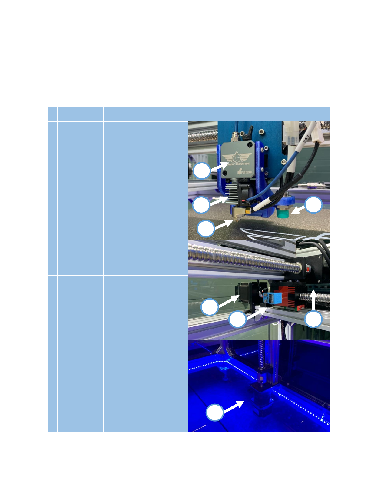
#
Component
Description
Image
1
Extruder
Stepper motor that pushes
filament through the
hotend.
2
Hotend
Component that heats up
filament to melting
temperature.
3
Nozzle
Small opening that filament
comes out of to print with.
4
Inductive
Probe
German designed sensor
that detects the distance
from the nozzle to the bed –
teal tip.
5
Endstop
Sensor that detects the x
home position of the printer.
There are two y endstops on
the front of the machine.
6
X Motor
Stepper motor responsible
for moving print head
assembly left to right.
7
Y Motor
Stepper motor responsible
for moving print head
assembly front to back.
There are two of these.
8
Z Motor
One motor on each side
controlling up and down
movement of the bed.
These have a 10:1 gear box
on them to increase power.
There are two of these.
8
7
3
2
4
6
1
5

8
9
Filament
Sensor
Detects when filament has
run out and cleans it as it
passes through. This is found
in the control case on the
right side.
10
Casters
Allows the printer to roll or
be locked in place with
retractable feet. The feet
can be raised and lowered
by rotating the leveling feet.
11
Switch Panel
Controls the printer power:
See the Powering the Printer
On section to see what
each control does.
12
Control Case
Houses all of the electronics
for the printer. This includes
power supply, duet board,
relays, and cooling fans.
13
Duet 2 Wifi
Screen
The interface used to
interact with the printer.
14
Heated Bed
Indicator
Red indicator light that turns
on when the heated bed is
above 40C. The PEI Print
Plate should not be
removed if this light is on
15
Hotend
Indicator
Red indicator light that turns
on when the hotend is
above 40C.
10
9
15
5
12
11
13
1
14

9
16
PEI Print Plate
Removable print surface for
easy remove prints.
17
MIC6 Plate
The plate that is heated by
the heated bed.
18
Insulation
Retains heat from the
heated bed.
19
Leveling
Springs
Adjustable bed levelers.
These are factory set by
Filament Innovations staff.
20
Base Plate
Creates a stable base for
the print bed.
21
Filament
Chamber
Used to house up to 5 spools
of filament at a controlled
temperature and a low
humidity.
22
Temperature
Control
Interface used to control
the temperature of the
filament chamber. This is set
to maintain temperature at
35C.
23
Filament
Chamber
Indicator
Light
A red indicator light that
lights up when the heater is
on to maintain the chamber
temperature.
24
Heater
The 120 V heater that
maintains the temperature
of the dry chamber set by
the temperature control.
25
Main
Chamber
Indicator
Indicates the temperature
and humidity of the main
chamber.
17
19
18
16
20
23
23
21
24
24
22
ffff
25
25
10
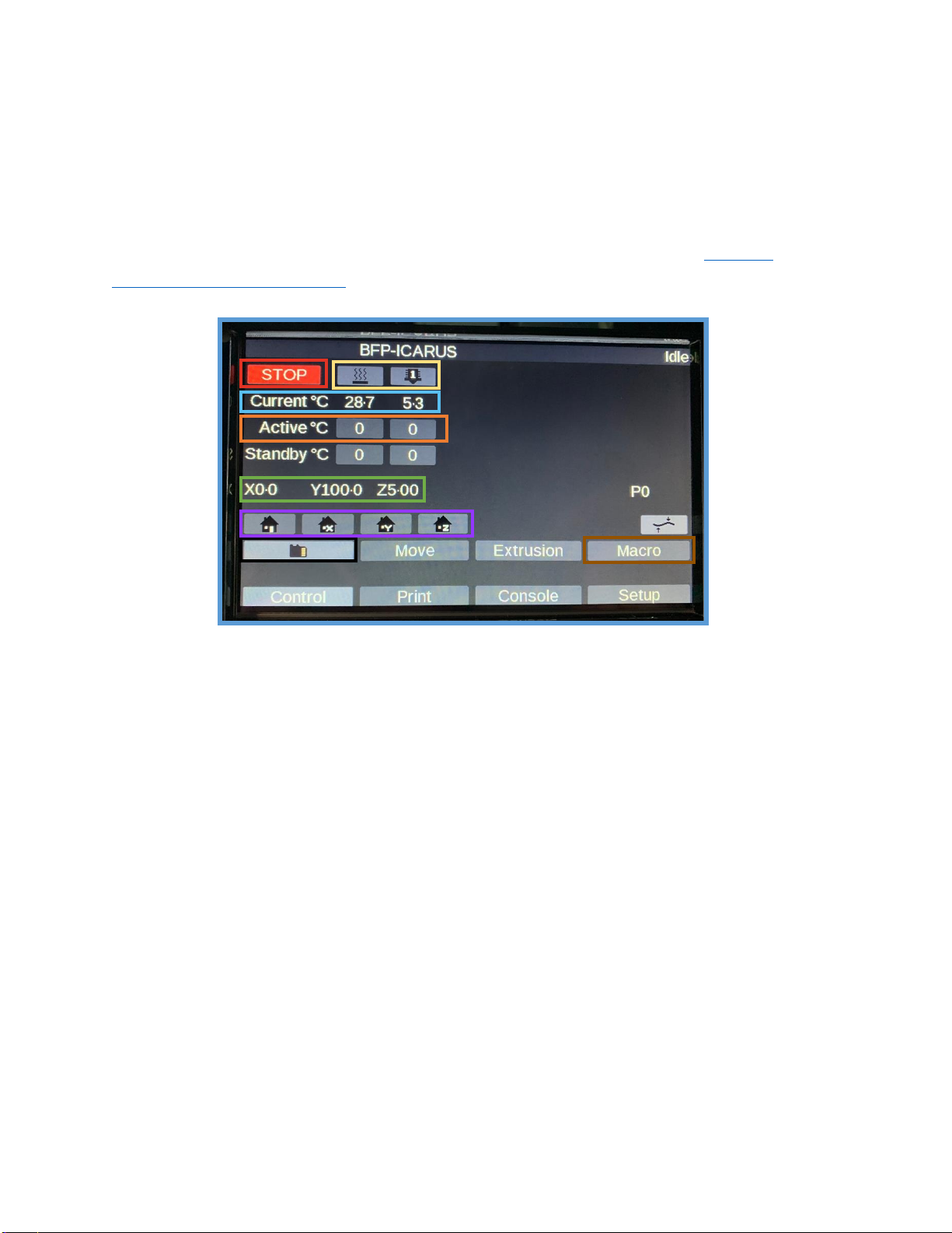
Touchscreen Interface
The BFP-ICARUS is equipped with a 7” PanelDue7i LCD touchscreen from
Duet3D to easily interact with the printer. In this section, we will cover the
basics required to understand how to operate your printer using the
touchscreen. For more in depth documentation, refer to the Official
Duet3D Documentation.
Red: Software controlled emergency stop.
Yellow: Heated Bed (Left) and Hotend (Right) icons.
Blue: Current temperature in Celsius.
Orange: Temperature the printer is set to.
Green: Current position of the X, Y, and Z axis in millimeters.
Purple: Home command for each axis. The left icon is a Home All.
to home all three axes. You must Home All before attempting
to use the Move commands. You can individually home each
axis with the other three buttons.
Black: All gCode files for printing that are stored on the onboard 4 GB
MicroSD card. These gCode files are loaded via the Duet
Web control interface on a computer browser.
Brown: The Macro button is used to store custom commands that can
be written and stored via the Duet Web control interface.
Some basic Macros are included to help with setup.
11
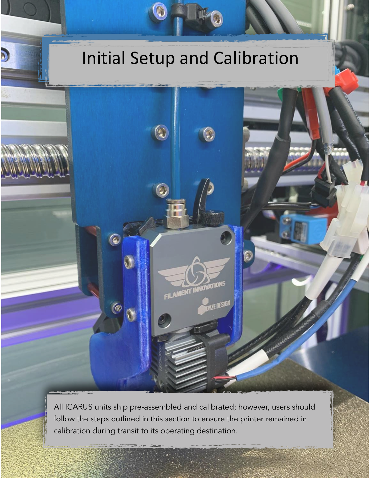
Initial Setup and Calibration
Initial Setup and Calibration

12
Tools and Accessories
Your printer has come with the following tools and accessories:
Toolbox Contents
•
Metric Allen Key Set
•
Bubble Level
•
Snips/Pliers
Accessories
•
110VAC Power Cord
•
Filament
•
Wyze IP/Internet WebCam
Leveling the Machine
Using the supplied bubble level, a 19 mm wrench, and the stabilizer feet
on the bottom, level the machine with the earth. Do this by placing the
bubble level on the top of each side of the machine and adjusting the
stabilizer feet as needed. During this, the stabilizer feet will be lowered and
the casters raised in the air. The machine is level when the bubble is
between the two lines, pictured below.
Before Adjusting the Casters: After Adjusting the Casters:

13
Powering the Unit On, Off, and Troubleshooting
The ICARUS printers run on 110 VAC power, the standard USA household
electricity –the unit needs a 15A circuit for operation. The switches on the
front of the control box are responsible for turning on and off the printer.
As a reminder, the function of each control is listed below.
•Red Toggle Switch: Controls power to the printer (Red Arrow)
•Blue Toggle Switch: Controls internal LED lighting (Blue Arrow)
•Emergency Stop: Kills all power in case of emergency. If pressed, turn
the button clockwise to disengage. (Green Arrow)
•Main Power Plug: Plug for 110 VAC power cord. (Yellow Arrow)
Steps for Turning on your ICARUS
1. Use the supplied 110 VAC power cord to plug the printer into a wall
outlet. The unit should be on a minimum 15 amp breaker; however, we
strongly suggest a 20 amp breaker.
2. Ensure that the emergency stop is disengaged. If engaged, turn
clockwise to disengage the button.
3. Flip the red toggle switch to turn on the printer. At this point the screen
and the cooling fans on the control box should turn on. You may also
turn on the LED’s using the blue toggle switch.
REAR
FRONT

14
Steps for Turning off your ICARUS
1. Press the System Cool Down button on the home screen to turn off the
heated bed and hotend.
2. Wait for the red Heated Bed and Hotend indicator lights to turn off.
3. Flip the red toggle switch down to power the unit off.
Troubleshooting the Power
The BFP-ICARUS is a straight forward machine to power on and off,
however there may be times when troubleshooting may occur.
•20amp Breaker –A breaker is located inside the control box, on the
bottom right. If the unit does not turn on, there may have been a
power surge on the electrical line the printer is plugged into. Please
check to see if the breaker has a green(off) or red (on) color on it. If
it is green, please flip the breaker to power the unit back on
•Emergency Stop –Is the emergency stop pressed in? This will cut
power immediately to the unit. Turn this clockwise to disengage it.
•Power Plug –Please check that the plug is fully inserted into the
control case on the back of the machine.
15
Bed Height Adjustment and Automatic Leveling
Keeping a level bed is critical for accurate 3D Printing. Every ICARUS unit
comes equipped with mesh bed leveling to ensure a flat bed. Even
though your bed leveling, and Z-offset is factory set, it is important to
check that no damage occurred during shipping.
Steps for Checking Bed Height and Leveling
1. Every ICARUS unit ships with light tension springs with locks nuts. Check
that all four are on the bed plate, one in each corner with a locknut
underneath it. These are factory set as level and every ICARUS ships
within 200-300 micron bed variance.
2. Use the Home All button to home the X, Y, and Z axes. The printer axes
will now start to move. This is shown in yellow
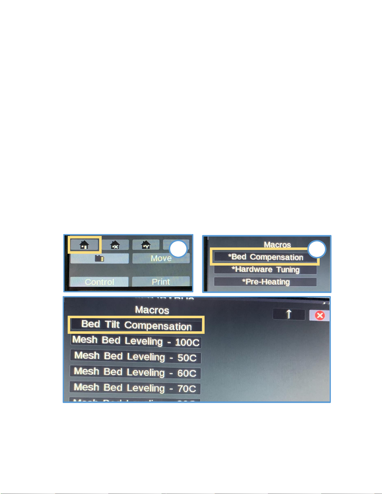
3. Navigate to the Bed Tilt Compensation macro by going to:
Macros > Bed Compensation > Bed Tilt Compensation
2
3

16
Automatic Bed Leveling and Baby Z Stepping
3D Printing requires a very flat bed surface for large, successful prints.
Because of this, we have included two forms of bed leveling for your
machine. This section of the guide is to inform you of what these two bed
leveling options do.
Inductive Probe: This durable and extremely accurate German
designed sensor is responsible for detecting the metal PEI print plate to
allow for the following functions to be run. This sensor can be found on
the hotend with the circular green cap at the bottom where it senses.
Tilt Compensation: Prior to every print, the ICARUS will automatically
perform a Tilt Compensation which probes the left center and right
center of the print bed. The software will automatically calculate the
deviations of the bed and independently adjust one of the Z motor
ballscrews to level the bed to ensure your print bed is flat every time.
Mesh Bed Leveling: Changes in bed temperatures from printing with
different filaments will slightly effect the levelness of the bed. A Mesh
Bed Compensation is a 5 minute Macro that will probe the bed at
numerous points, twice, and create a virtual height map of the bed. It
is found under:
Macros > Bed Compensation > “Mesh Bed Leveling”.
Run this macro every time you load a new filament to ensure a proper
print surface. There are presets from 50C through 100C bed
temperature, choose the temperature that best suits your printing
needs. Our ICARUS units come pre-calibrated with a mesh variance
under 300 microns.
Baby Step: To ensure you get the perfect first layer every print, the Duet
system allows you to move the print bed up or down at the beginning
of a print to account for small variations in bed leveling from normal
use. When a print is started, a button on the lower right of the
touchscreen called “Baby Step” will allow you to adjust the spacing of
the print head to the print bed in 0.02mm increments. The two arrows
pointing together will raise the print bed to the nozzle. The two arrows
pointing away will lower the print bed from the nozzle.
17
Moving the Printhead
The print head can be moved using the Move tab on the touchscreen.
After selecting the Move button on the home screen on the touchscreen,
the Move window appears. This gives a variety of options for moving the
printer a certain number of millimeters in all directions.
The printer must be homed before it can be
moved manually. If a move button is pressed
without the printer being homed, an error
message will appear. This is necessary to
prevent damage to the machine by moving
the printer too far in one direction.
Moving in the X and Y Direction
The X and Y direction moves the PRINTHEAD. Once the printer is homed, it
can be moved in the X and Y direction freely without fear of moving the
printer too far in either direction.
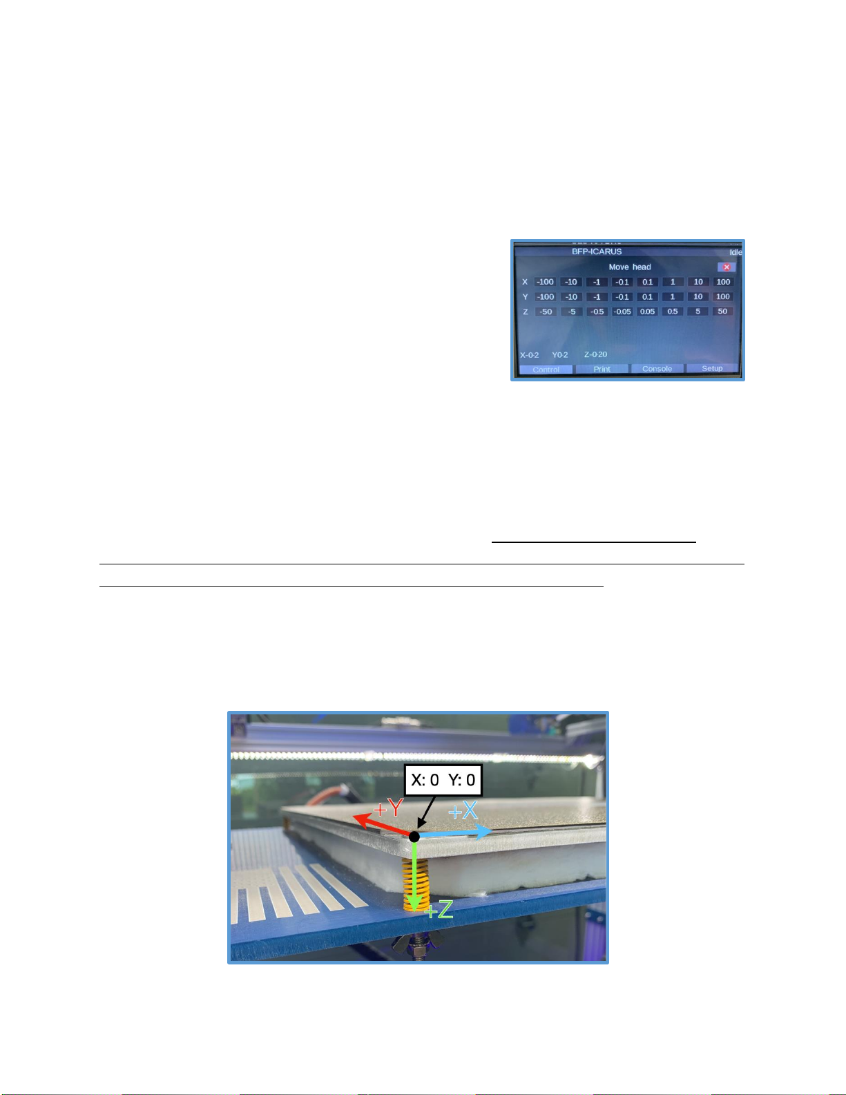
Moving in the Z Direction
The Z direction moves the BED up and down. More caution has to be
given when moving in the Z direction because it is possible to ram the bed
into the nozzle which can SEVERELY damage the machine. Take extra
caution when moving the Z axis. The negative Z buttons move the print
bed UP while the positive Z buttons move the print bed DOWN.
The diagram below shows what the positive direction of movement is for
each axis. The origin of the x and y axis of the printer is in the front left.

18
System Preheating
In order to preheat the entire system, the desired temperature needs
to be set for the hotend and heated bed individually. Other than
preheating for a print, the heated bed must be preheated for Mesh
Bed Leveling, and the hotend must be preheated when changing
filament. For more information about preheating instructions when
changing filament, see the next section Filament Loading.
Steps to Preheating the Bed and Hotend
1. Press the temperature button in the “Active”
row for the hotend.
2. Use the + and –buttons to select the desired
temperature and then press the “Set”button.
3. Initiate the heating process by pressing the
hotend icon. The hotend will start to heat up.
4. The same process is followed for preheating
the heated bed. Press the temperature button
in the “Active” row for the heated bed, set
the desired temperature, and press the
heated bed icon to initiate the process.
Alternative Method for Preheating
There are also Macros made for system
preheating ABS, ASA, Nylon, PETG, PLA, TPU and
more. When one of these is engaged, the system
will heat the heated bed first and then the
hotend. Find these under
Macros > “Pre-Heating”
Always print at the manufacturer’s suggested
temperatures. Our preheating macros should be
treated as guidelines for that polymer.
1
2
3

19
Filament Loading
To begin printing with your printer, or to change filament, it is important to
know how to load filament into your ICARUS. Follow the two guides below
for Loading Filament for the First Time and Changing Filament.
Loading Filament for the First Time
1. Put the desired spool of filament on
any of the filament holders in the
filament chamber.
2. Preheat the hotend to the correct
temperature for that filament.
3. Cut the end of the new filament at a
45 degree angle to allow it to more
easily be fed through the tube.
4. Push the lever on the extruder to the
left (Green Box) and push the small
lock knob to the right (Blue Box) –this
opens the gear inside the extruder.
5. Start feeding the filament through the
tube, through the sensor, and
continue feeding it until you feel it stop
–it has now entered the extruder.
6. With the hotend heated and
filament in the extruder, release the
filament lever by pushing it to the left
to release it. The lever should now be
tilted to the right (Red Box).
7. On the Duet Screen, press the Extrusion
button to extrude 100mm of filament
at 5mm/s –twice –so you extrude
200mm of filament. If the extruder does
not move, then press the Home All
button to home all the axes as a safety
precaution and repeat this step.
7
1
4
6
3
5

20
Steps to Changing Filament
1. Preheat the hotend to the correct temperature. If you are switching
between different materials (i.e. PETG to PLA), it is suggested to load the
filament at a temperature between the two ranges. This will soften the
PETG enough for getting it out of the hotend and the PLA will not be
burned when you load it.
2. Push the lever on the extruder to the left and engage it into place with
the lock knob.
3. Remove the existing filament by spinning the spool backwards. You can
also remove the blue PTFE tube, at the connector on the hotend, if it is
easier to pull the filament directly out of the extruder.
4. Once the old filament has been pulled out of the tube, put the new
spool of filament on and follow the filament loading steps from the prior
section.
5. When printing, immediately after changing the filament, remember to
preheat the hotend and heated bed to the appropriate temperature
for the new filament.
Once filament has been loaded into the printer, the initial setup and
calibration has been completed. The next section will provide more
information on setting up the software and internet connectivity of the unit.
Other manuals for BFP-ICARUS
1
Table of contents
Other FLAMENT INNOVATIONS 3D Printer manuals


