Flamerite Fires Little Atom User manual

Page 1 of 4
Flamerite Little Atom Electric Stove
1. Installation of Stove
WARNING: Please ensure the following are strictly adhered to upon installation.
A minimum clearance of 40mm is required around the top, both sides and to the rear of the stove. If not this may cause
the heater to cut out.
The Stove must be positioned so that the plug socket is accessible once installed. In the unlikely event of breakdown access
must be allowed to the rear of the Stove so that it may be serviced. The mains cable must therefore be long enough to
allow this. If the removal of the plug is absolutely necessary for installation, cut off within 100mm only of the plug itself.
Any further may affect your warranty.
Where the Stove is being used in an existing chimney, it is very important that the chimney and its drawn airflow are
completely blocked off to prevent directional airflow problems with the heater as well as the thermal cut out to activate.
Positioning the Stove.
Your Stove has primarily been designed for use as part of a fireplace suite although it may be used freestanding. Due to its weight
The Little Atom comes with its cast iron top and door packed separately so it may be better manoeuvred into position. If using in
conjunction with one of our Fireplace suites, a piece of glass is also supplied which should be placed on the hearth for the stove to
sit on.
(Optional) 150mm Fireplace Deeper Stove Insert
Before final fitting of the fireplace the Stove Insert must be attached to the mantle. We recommend this be done as close as
possible to the hole the fireplace is to be fitted.
Push the two together and screw the back panel to the mantle using the screws in the bag labelled red into the holes only
marked in red.
Secure the base with the screws in the bag labelled black into the holes only marked in black.
Next unscrew the connection box on the inside of the mantle leg (this should be left unscrewed) and connect the wires,
Live (brown) to Live (brown) and Neutral (blue) to Neutral (blue) from the stove insert. (12v)
Now gently push the fireplace into position.
Coal Fuel Effect Layout
The stove is supplied with two pieces of orange fuel bed, 1 flat, 1 U-Shaped, 8 orange coals, 6 small, 5 medium and 4 large ceramic
coals.
Place the flat orange fuel bed into the recess above the light bulbs, followed by the U-Shaped part onto and against the
back of the chamber, open area down. Fig.1
Next proceed with placing the 8 orange coals in any order into the chamber, 4 on top of the U-Shaped part and 4 in front
on the flat orange fuel bed. Fig.2
The 6 small ceramic coals, place in the chamber in front of the 4 most forward orange coals. Fig.3
The medium size ceramic coals, place all 5 across the middle of the fuel bed to the rear of the small ceramic coals, on top of
the front 4 orange coals. Fig.4
Continue laying the 4 remaining larger ceramic coals to the rear of the 5 ceramic coals just laid on top of the second set of
orange coals. Fig.5
The coal formation is subjective to the end user but we recommend the above steps to give the most authentic look. Please spend
time adjusting to suit.

Page 2 of 4
Fig.1 Fig.2 Fig.3 Fig.4 Fig.5
Log Fuel Effect Layout
The stove is supplied with a 1 piece flat orange fuel bed, a 1 piece moulded log effect fuel bed and 5 clay-moulded logs.
Place the flat orange fuel bed into the recess above the light bulbs, followed by the 1 piece moulded log effect fuel bed
against the back of the chamber.
The log formation is subjective to the end user but we recommend following the image in Fig.6 to give the most authentic
yet random look. Please spend time adjusting to suit.
Fig.6
Fitting the Cast Door and Cast Top
Unpack the door, top, 2 fixing pins and handle. Place the door on the stove at 45 degrees open and drop in a pin at the
bottom then the top through each swing bolt attached to the stove. Fig.7 the door will not openfully.
Close the door and turn the handle clockwise onto the exposed thread. Press down to tighten (do not over tighten) and
release to bring the handle into a downward position.
The cast top has four lugs at its base towards its rear, these will line up with corresponding holes on the very top of the
stove. Gently place the cast top on the stove. Fig.8
Fig.7 Fig.8
Fitting (Optional) Stove Flue Pipe
An optional flue pipe is available and may be used with the 150mm deeper stove insert. Quite simply place the round block
supplied with the flue pipe, magnets facing down into the recess on the cast top. Next place the flue pipe on top of the block. An
elongated hole in the top of the fireplace insert allows the stove and pipe to be centralised.
Electrical Connections
Your appliance comes fitted with a plug that incorporates a 13A fuse. The replacement fuses must be 13A and ASTA approved. If the
fuse cover is lost the plug must not be used until a replacement cover, of the same colour, is obtained from an electrical retailer.
The appliance is fitted with a moulded plug if it is necessary cut off the plug, for any reason, it must be discarded immediately
with the fuse removed. Under no circumstances should any attempt be made to reuse the plug, do not insert into any 13A
socket as this could cause a hazard. If the mains cable is damaged it must be replaced by the manufacturer or an authorised
technical service centre.

Page 3 of 4
WARNING THIS APPLIANCE MUST BE EARTHED
IMPORTANT
The wires in the mains lead are coloured in accordance with the following code.
Green and yellow:
EARTH
Blue:
NEUTRAL
Red:
LIVE
As the colours of the wires in the mains lead of this appliance may not correspond with the colour markings in your plug proceed as
follows: -
The wire which is coloured green and yellow must be connected to the terminal in the plug which is marked with the
letter E, or coloured green or coloured green and yellow, ormarked with the earth symbol
The wire which is coloured blue must be connected to the terminal in the plug which is marked with the letter N, or
coloured black.
The wire which is coloured brown must be connected to the terminal in the plug which is marked with the letter L,
or coloured red.
2. Operating the fire
The Little Atom’s controls are located at the back of the stove towards the top right hand corner. Further functions can be
operated either by remote handset or keypad or manually.
Controls (Remote)
The main on/off switch is marked with I/O and will need to be switched to I to operate the stove and illuminate the
fuel bed only. In this position you will be unable to operate the stove further unless the button on the remote or
keypad is pressed first.
To operate the flame effect (and further functions) simply press and release button on the remote or keypad.
To set the flame effect to your desired brightness press then release + or - buttons marked either side of the
icon.
For 1KW of heat, press then release the button marked O/I. To increase the temperature to 2KW press then
release button marked I/II. You may alternate from 1KW to 2KW by pressing I/II at anytime. To turn the
heater off, press then release the button marked O/I. The heater will always start in the lower setting
To turn the flame effect off and deactivate the heater and dimmer functions press then release the button
marked .
To turn the stove off completely the main on/off switch on the back of the stove must be switch back to O.
3.2 Controls (Manual)
The main on/off switch is marked with I/O and will need to be switched to I to operate the stove and illuminate the
flame effect.
For heating the controls are located under the on/off switch. For 1kw of heat push the switch marked with a single
bar I. For 2kw of heat push the switch marked with the double bars II. Both switches have to be depressed for 2kw
of heat. The flame effect has to be illuminated for the heater to work.
Areas around the fire will become hot when activated. We strongly recommend small children be kept away from having any direct
contact with the appliance by means of fitting a fireguard. This appliance is not intended for use by persons (or children) with reduced
physical sensory or mental capabilities or lack of experience or knowledge unless they have been given supervision or instruction
concerning the use of the appliance by the person responsible for their safety. Children should be supervised to ensure they do not
play with this appliance.
3. Maintenance
Warning: Before any maintenance/cleaning is undertaken always disconnect the fire from the mains power supply.
Replacing the fuel effect lamps
Your Stove uses two 7w E14 lamps to illuminate its fuel effect. Replacement lamps are available from Flamerite Fires and its
stockists (see top of page 1). Please note that replacement lamps are not covered under warranty.
Unscrew the door handle by applying pressure and turning anti-clockwise; open the door (will not open fully).
Remove the fuel effect and the two orange fuel beds. A hole will be visible to allow a thin electrical screwdriver to be insert
enabling the base fuel bed to be removed.
Unscrew the lamp and replace.
Replace the orange fuel bed and fuel effect. See section 2.3 & 2.4 under installation.

Page 4 of 4
Replacing LED Projection lamp
Tool Needed, Phillips Screwdriver. Your Stove uses a 6w LED 4000k GU10 lamp with a 25 degree beam angle for its flame effect.
Replacement LED lamps are available from Flamerite Fires and its stockists (see top of page 1). Please note that replacement LED
lamps are only covered by a two year warranty.
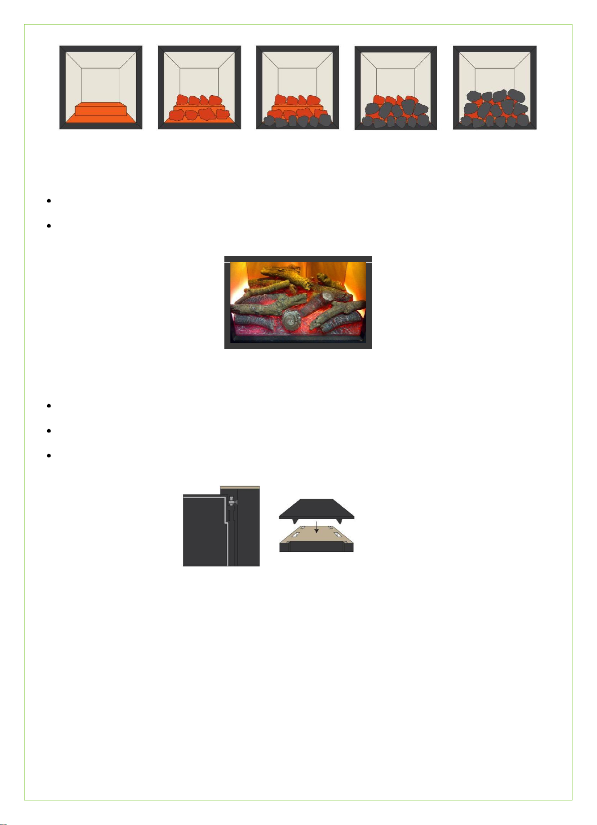
To gain access the cast top must first be removed Fig. 8 See section 2.5 under installation. Remove the ten screws from
around the perimeter of the top plate and lift along with the projector carefully out of the stoveFig.9.
Separate the lamp connecter from the lamp by twisting it anti-clockwise and remove the screw from the clamp holding the
lamp. Fig.10
Release the lamp by pulling upward then away, the clamp will bend forward. Fig.11.
Insert the new LED GU10 pushing down making sure it clicks into place, replace the screw in the clamp and reattach the
lamp connector. Fig.12
Carefully replace the projector back into the stove and replace the screws. Fig.9.
Finally gently reposition the cast top. Fig.8. See section 2.5 under installation.
Fig.9 Fig.10 Fig.11 Fig.12
Changing battery in the remote
Your remote uses a CR2032 Lithium Battery, replacements are available from Flamerite Fires stockists, most electrical or
photographic stores. Ensure battery is disposed of safely. Do not dispose of in fire, do not swallow and keep away from children.
Cleaning
The stove can be cleaned with a lint free cloth and a non abrasive cleaner. To prolong the life of the fan heater, we recommend
vacuuming areas around the inlet vent to the rear of the stove and the outlet vent beneath regularly to remove dust from around or
on the impellor.
4. Warnings
Do not use the stove in the vicinity of a bath shower or swimming pool.
Never use the stove to dry laundry.
Never install the stove directly underneath a fixed main socket.
Never cover the appliance during the operation of the stove.
The use of an extension lead is not recommended.
Particular caution should be applied to ensure that children do not play with the fuel effects.
As with any electrical appliance whilst the instructions aim to cover as many eventualities as possible, caution and common
sense should be applied when operating your appliance, particularly in the vicinity of small children.
5. Problem solving
No power to the stove: Check the wall socket, plug, fuse and lamps.
No illumination: Make sure stove is turned on. Check heater is working, if so check lamps, if not see above.
Illumination but no heat: The safety cut may have operated. See below*. Check there is a gap to the rear of the stove to
the back of the fireplace, minimum 40mm.
Noise when illuminated: Due to moving parts, the electric stove will make a noise.
Noise from the heater when in use: The sound of rushing air is normal.
*Automatic safety cut out: The heater is fitted with an automatic cut out to prevent any damage due to overheating. The
element will continually and automatically cut out if the airflow is obstructed. Never cover the air inlets or outlets. To
reset, switch the stove off, disconnect from the mains supply, remove the cause of overheating and allowed to cool for a
suitable period then switch the stove back on. Caution: In order to avoid a hazard due to inadvertent resetting of the
thermal cut out, the appliance must not be supplied through an external switching device, such as a timer, or connected to
circuit regularly switched on and off by a utility.
Table of contents
Other Flamerite Fires Stove manuals