FLAMMA F65 Eagle Operating and maintenance manual

®
®
FIAMMASTORE
fiamma.comfiamma.com
MARKISEN
AWNINGS
STORES
TENDALINI
TOLDOS
Montage und
Gebrauchsanleitung
Installation
and use instructions
Instructions de montage
et mode d’emploi
Instrucciones
de montaje y uso
Istruzioni
di montaggio e d’uso
DE
EN
FR
ES
IT
POLAR WHITE
TITANIUM
12Vdc12Vdc
A0\IS\98690-209 rev.A
2
®
®
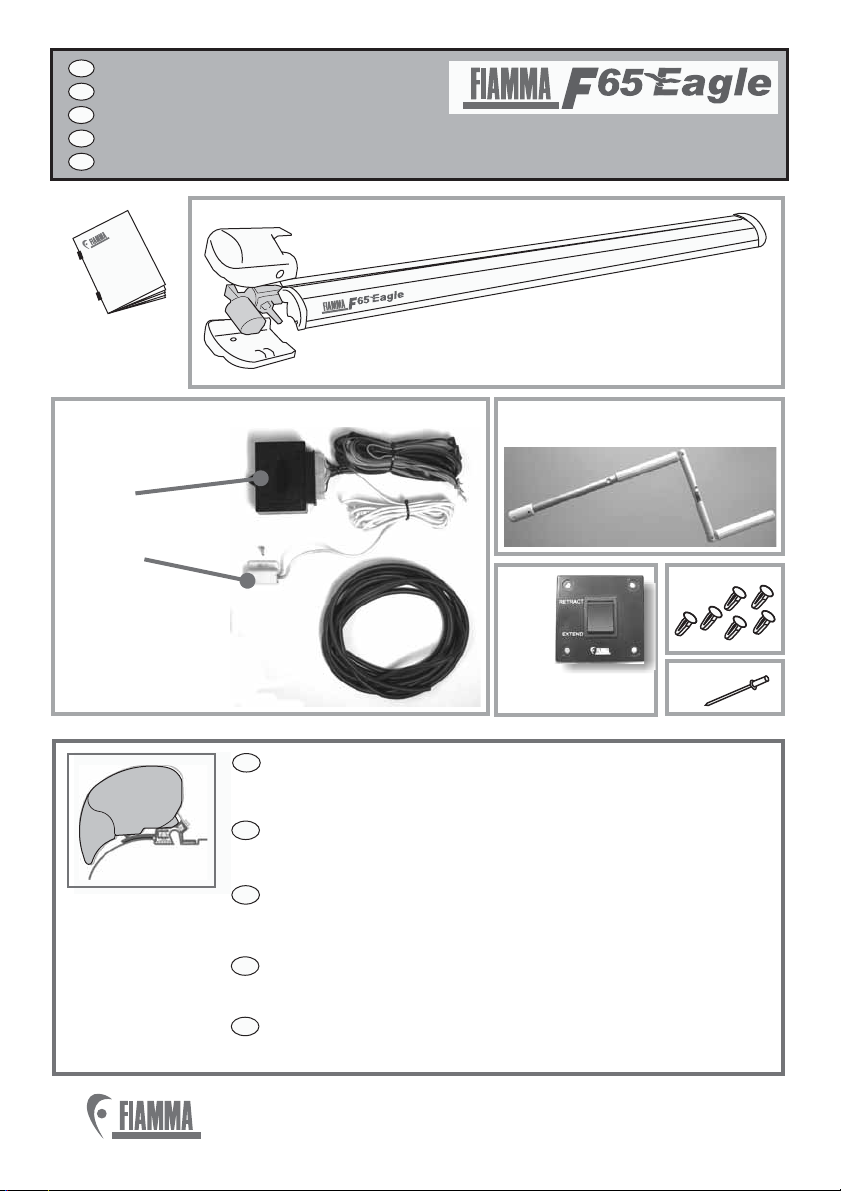
VERPACKUNGSINHALT
PACKAGE CONTENTS
CONTENU DE L’EMBALLAGE
CONTENIDO DEL EMBALAJE
CONTENUTO DELL’IMBALLO
DE
EN
FR
ES
IT
1x
1x
N
O
Control System
®
®
P
Control
Unit
and
Sismic
Sensor
E2
E1
Um die Halterungen zu befestigen, befolgen Sie bitte
die jeweiligen Montageanleitungen.
To install the bracket, not included, pls. follow the specific
installation instructions
Pour fixer la patte, non fournie, nous vous conseillons de
vous tenir aux instructions de montage spécifiques.
Para la fijación del estribo, no suministrado,
atenerse a las instrucciones específicas por cada modelo
Per il fissaggio della staffa, non fornita, attenersi alle
istruzioni di montaggio specifiche per modello.
DE
EN
FR
ES
IT
Adapter F65 EAGLE
R
S

®
®
3
®
®
3
Um die Markise optimal nutzen zu k , lesen Sie bitte die Bedienungsan-
leitung aufmerksam durch und bewahren sie zur sp
To use the awning in the best way, read the user’s instructions carefully and
keep them on hand for consultation in the future.
Pour tirer le meilleur parti de votre store, nous vous invitons
d’emploi et les conserver pour toute consultation ult
önnen äteren Verwendung gut auf.
lire attentive-
ment les notices érieure.
à
à
Para usar el toldo en lo mejor de los modos, os invitamos a leer atentamente
las instrucciones de uso, guardándolas en caso de necesidad.
Per utilizzare al meglio il tendalino, vi invitiamo a leggere attentamente le
istruzioni d’uso e a conservarle in caso di necessita’.
DE
EN
FR
ES
IT
SISMIC
SENSOR
MICRO
SWITCH
E2
OCONTROL
SYSTEM
E1
BATTERY
12V
P
CONTROL UNIT
ENGINE
CONTROL
UNIT
4
®
®
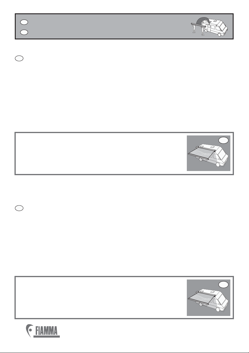
MONTAGEANLEITUNG
INSTALLATION INSTRUCTION
DE
EN
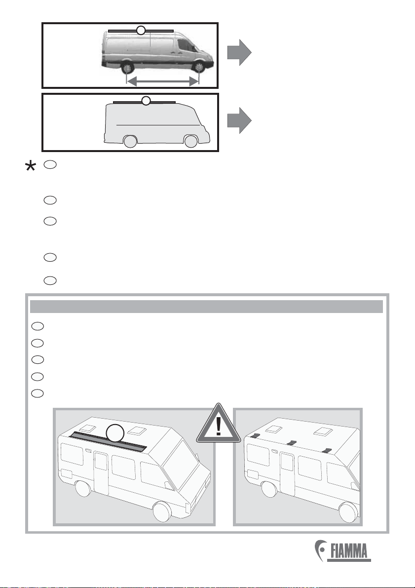
1. Die Montage soll von fachkundigem Personal durchgeführt werden.
2. Suchen Sie zur Anbringung der Markise die Stellen mit den
Wandverstärkungen aus.
3. Die Markisenkassette muss waagerecht montiert werden.
4. Vergewissern Sie sich vor dem Bohren der Montagelöcher,
dass im Inneren des Fahrzeugs an den vorgesehenen Stellen keine
Hindernisse, insbesondere Gas- oder Stromleitung, liegen.
5. Ziehen Sie die Blockierschrauben der Halterung nicht zu fest an.
6.
.
Positionieren Sie die Blockierschraube auf die Halterung und befestigen
Sie diese
1. The installation must be carried out by qualified persons.
2. Check the wall of the vehicle and verify the position of the reinforced
points or request this information from the seller of your vehicle.
3. Make sure that the awning is installed horizontally.
4. Before drilling, make sure that there are no obstacles inside.
(e.g. Electric cables, gas pipes etc).
5. Fasten the bracket, but be careful not to over tighten the lock nuts.
6. Place the awning on the bracket and fasten it.
DE
EN
DE
EN
Die EAGLE ist eine selbsttragende Markise, vergewissern Sie
sich daher bitte, dass die Fahrzeugwand stabil genug ist, um
die Markise und das dazugehörende Zubehör tragen zu
können; bitte nur mit den im Lieferumfang beigefügten
Halterungen, die für diese Markise bestimmt sind, anbringen.
EAGLE is a special awning with self supporting arms: make
sure that the wall of the vehicle is solid enough to support the
awning and its pressures;use only the standard delivered
brackets especially designed for this product.
®
®
5
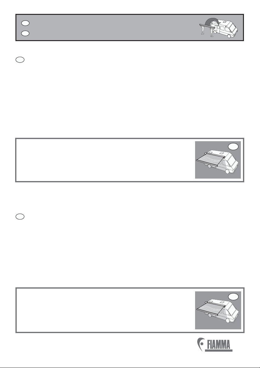
INSTRUCTIONS DE MONTAGE
INSTRUCCIONES DE MONTAJE
FR
ES
ES
FR
1. Le montage doit être effectué par des techniciens compétents
2. Testez la paroi du véhicule et vérifiez la position des points d’ancrage ou
informez-vous auprès du revendeur de votre véhicule.
3. Montez le store en position horizontale.
4. Avant de percer, assurez-vous qu’il n’y ait pas d’obstacles à l’intérieur du
véhicule (par ex. câbles électriques, tubes de gaz, etc.)
5. Fixez en faisant attention à ne pas serrer
excessivement les écrous de blocage.
6.
l’étrier
Placez le store sur l’étrier et fixez-le.
1. El montaje tiene que ser efectuada por el personal competente
2. Sondar la pared del vehículo y verificar los puntos reforzados o
informarse cerca del revendedor del propio vehículo.
3. Montar el toldo perfectamente horizontal.
4. Antes que taladrar, asegurarse que no haya obstaculos en el interior
(cables electricos, tubos..).
5. Fijar el estribo, poniendo atención en no estrechar
excesivamente los dados de blocaje.
6. Colocar el toldo sobre el estribo y fijarlo.
EAGLE est un store spécial avec bras autoportants :
s'assurez-vous que la paroi du véhicule est assez solide pour
soutenir aussi bien le store que ses sollicitations.
Utilisez uniquement les pattes conçues pour cet article.
FR
ES
EAGLE es un toldo especial con brazos autoportantes:
asegurarse de que las paredes del vehículo sean bastante
sólidas para sostener el peso del toldo y sus solicitaciones;
usar exclusivamente los estribos para este producto.
6
®
®
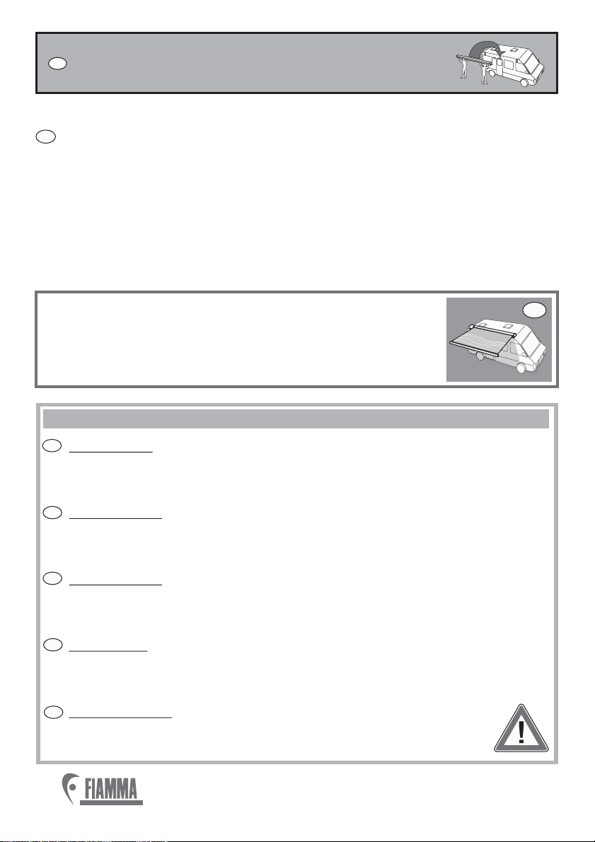
ISTRUZIONI DI MONTAGGIO
IT
1. Il montaggio deve essere eseguito da personale competente.
2. Prima di effettuare l’installazione, sondare la parete del mezzo verifican-
done i punti rinforzati e informarsi presso il rivenditore del proprio mezzo.
3. Accertarsi che il tendalino venga sempre montato orizzontalmente.
4. Prima di forare, accertarsi che non vi siano ostacoli all’interno come cavi
elettrici, tubi passaggio gas, etc.
5. Fissare la staffa facendo attenzione di non stringere eccessivamente i dadi
di bloccaggio.
6. Solo dopo aver verificato i punti di cui sopra, posizionare il tendalino sulla
staffa e fissarlo.
IT
La F65 EAGLE è un tendalino speciale a braccia autoportanti:
assicurarsi che le pareti del mezzo siano sufficientemente
solide per supportare sia il tendalino che le sue sollecitazioni;
usare esclusivamente .le staffe dedicate a questo prodotto
IT
DE
EN
FR
ES
IT
ACHTUNG -
ATTENTION -
ATTENTION -
CUIDADO -
ATTENZIONE -
Regelmässig die Befestigung der Halterungen kontrollieren.
Achten Sie vor allem nach dem ersten sicherstellen darauf, dass
Periodically check the brackets to make sure it is firmly
attached (especially after the first kilometers) make sure the belts are not
loose and that holding brackets have not shifted.
Contrôlez périodiquement l’état de fixation des pattes
(surtout après les premiers kilomètres) en vous assurant que les
supports de fixation n’aient pas bougé.
Controlar periodicamente el estado de fijación de los
estribos (sobretodo después de los primeros Kms) asegurándose que
no se desplacen.
Controllare periodicamente lo stato di fissaggio
delle staffe (soprattutto dopo i primi chilometri) assicurandosi che
Le stesse non si siano mosse e che i serraggi siano corretti.
sich
die Haltebügel nicht verschoben haben.
IMPORTANT WICHTIG CUIDADO IMPORTANTE
®
®
7
ADAPTER MERCEDES
SPRINTER F65 400
CODE: 98655-768
ADAPTER F65 EAGLE 400
CODE: 98655-969
DE
EN
FR
ES
IT
DE
EN
FR
ES
IT
OK
A
NO
IMPORTANT WICHTIG CUIDADO IMPORTANTE
ACHTUNG: Bitte ausschliesslich die Adapter der F65 EAGLE verwenden.
CAUTION: Use only the adapters for the F65 EAGLE.
PRECAUCION: Usar solo los soportes para el F65 EAGLE.
ATTENZIONE: Usare esclusivamente gli adapter per la F65 EAGLE.
ATTENTION : Utilisez exclusivement les étriers conçus pour le F65 EAGLE.
Bitte informieren Sie sich bei Ihrem Händler hinsichtlich der
verstärkten Punkte am Fahrzeug.
Check with your dealer the reinforced points of your vehicle.
Adressez-vous au concessionnaire du véhicule pour des informations sur
les points d’ancrage.
Verificar con su distribuidor los puntos reforzados del vehículo.
Informarsi presso il rivenditore del proprio mezzo sui punti rinforzati.
A
MOTORHOME
MERCEDES
SPRINTER
A
4325 mm
8
®
®
A
A
A
DE
EN
FR
ES
IT
ANBRINGUNG DER HALTERUNG AM FAHRZEUG
INSTALLATION DE L’ÉTRIER SUR LE VÉHICULE
INSTALLATION OF THE BRACKET ON THE VEHICLE
MONTAJE DEL ESTRIBO EN EL VEHICULO
MONTAGGIO DELLA STAFFA SUL MEZZO
Um die Halterungen zu befestigen, befolgen Sie bitte
die jeweiligen Montageanleitungen.
To install the bracket, not included, pls. follow the specific
installation instructions
Pour fixer la patte, non fournie, nous vous conseillons de
vous tenir aux instructions de montage spécifiques.
Para la fijación del estribo,no suministrado, atenerse
a las instrucciones específicas por cada modelo.
Per il fissaggio della staffa, non fornita, attenersi alle
istruzioni di montaggio specifiche per modello.
DE
EN
FR
ES
IT
Adapter F65 EAGLE
1

®
®
9
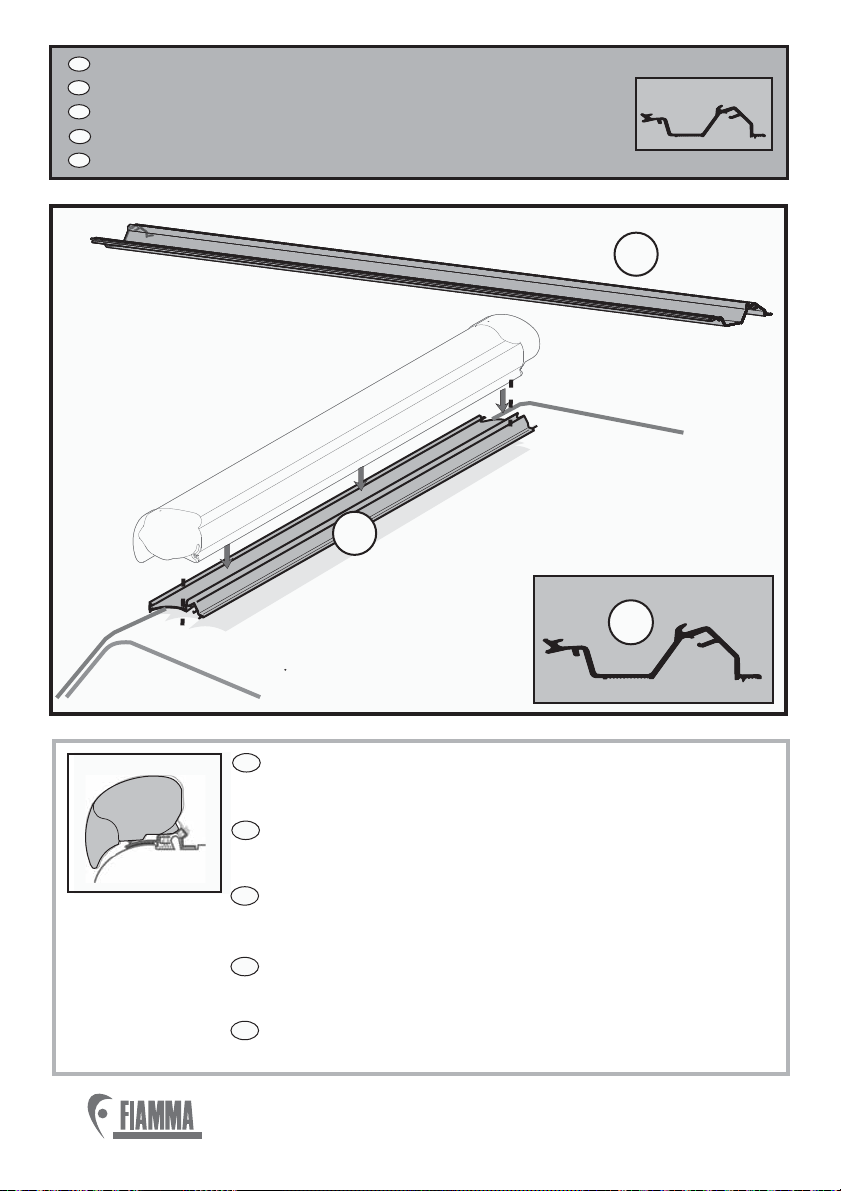
ANBRINGUNG DER MARKISE AN DEN HALTERUNGEN
INSTALLATION DU STORE SUR L’ÉTRIER
FIXING OF THE AWNING ON THE BRACKET
MONTAJE DEL TOLDO SOBRE EL ESTRIBO
MONTAGGIO DEL TENDALINO SULLA STAFFA
DE
EN
FR
ES
IT
A
Bitte immer die Sicherheits-
schrauben benützen.
Please use always the
security screws.
Utilisez toujours les vis
de sécurité.
Poner siempre los
tornillos de seguridad.
Mettere sempre le viti
di sicurezza.
DE
EN
FR
ES
IT
23
4

10
®
®
N
Öffnen der Markise
Open the awning
Ouvrir le store
Abrir el toldo
Aprire il Tendalino
DE
EN
FR
ES
IT
5
IMPORTANT WICHTIG CUIDADO IMPORTANTE
DE
EN
FR
ES
IT
Attenzione Sicurezza Rimuovere questa etichetta di sicurezza solo
dopo aver fissato il tendalino sulla staffa.
Achtung Sicherheit Entfernen Sie die Etikette
nur nachdem die Markise an der Halterung
befestigt wird.
Attention Security Remove this label only after fixing the awning on
the bracket.
Attention Sécurité Enlevez l’étiquette seulement après la fixation du
store à l’étrier.
Atención-Seguridad Quitar esta etiqueta de seguridad solo después
de fijar el toldo sobre el estribo.
SUPPORT SUPPORT
6
IT
ES
FR
EN
DE
®
®
11
DE
EN
FR
ES
IT
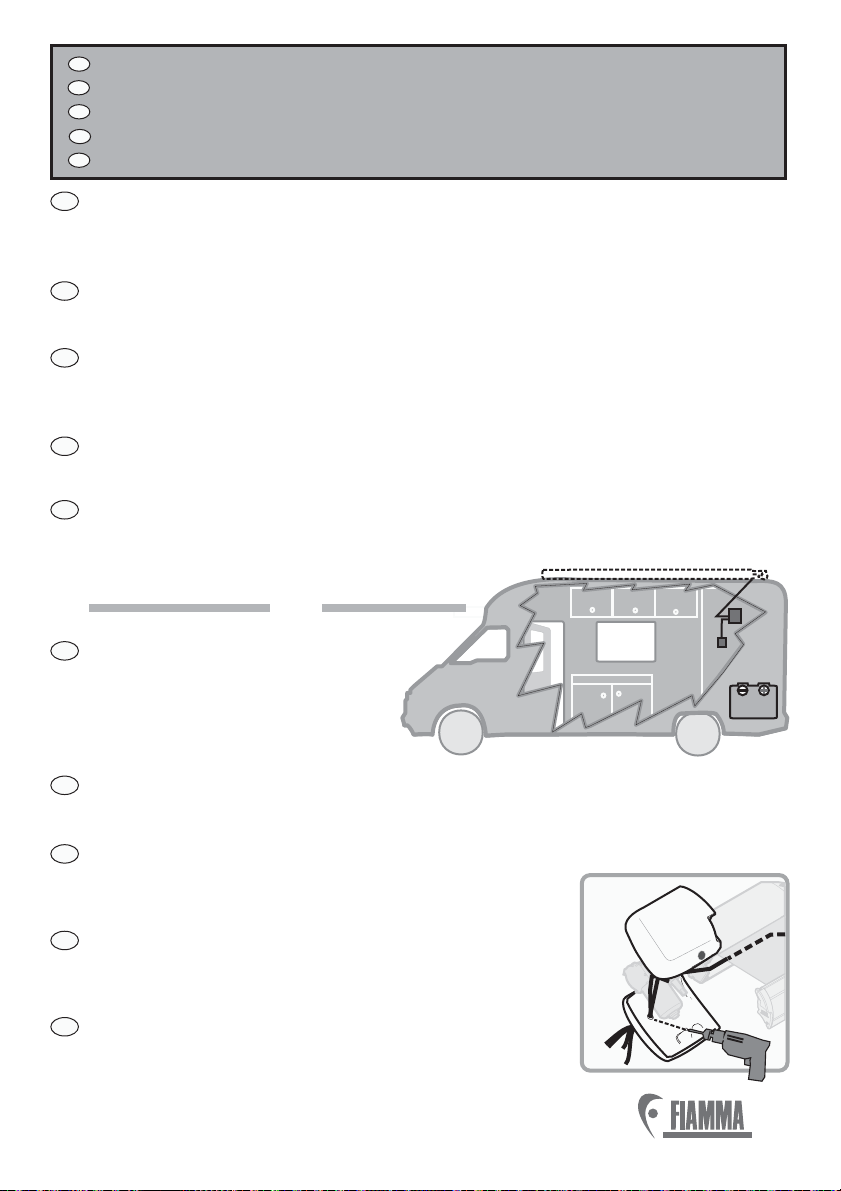
BEFESTIGUNG UND VERKABELUNG DES STEUERGERÄTES.
FIXATION ET CÂBLAGE DU BOÎTIER ÉLECTRONIQUE.
FIXING AND WIRING OF THE CONTROL UNIT.
FIJACION Y CABLEADO DE LA CENTRALINA.
FISSAGGIO E CABLAGGIO DELLA CENTRALINA.
7
ACHTUNG! Die Steuerung E1 muss im Innern des Fahrzeuges enstprechend
dem Motor angebracht werden. Die elektrische Installierung muss von
fachkundigem Personal durchgeführt werden.
ATTENTION ! Fixez de fixer le boîtier électronique (E1)àl’intérieur du
véhicule en correspondance du moteur. L’installation électrique doit être
effectuée par des techniciens.
ATTENTION! Fix the Control Unit E1 inside the vehicle by the motor.
The electrical system must be carried out by a qualified person.
¡ATENCION! Fijar la centralina E1 por dentro del vehículo a nivel del motor.
La conexión eléctrica tiene que ser efectuada por el personal competente.
ATTENZIONE! Prevedere di fissare la Centralina E1 all’interno del mezzo in
corrispondenza del motore. Il collegamento elettrico deve essere eseguito
da personale competente.
Control Sistem
Motor
Control Unit
E1
O
F65 EAGLE
BATTERY
12V
IT
ES
FR
EN
DE Vor der Verkabelung eine Bohrung
an der hinteren Motorabdeckung
durchführen, um dann die Kabel
des Sensors, des Motores und
des Mikroswitch durchzuziehen.
Before wiring, make a cable outlet on the back of the engine rear cover and
run the cables of the sensor, of the motor and the micro-switch.
Antes de cablear, hacer un agujero pasacables en la
parte posterior de la tapa trasera del motor y pasar
los cables del sensor, del motor y del micro-interruptor.
Prima di cablare fare un foro passacavi, sul retro
della cuffia-motore inferiore e far passare i cavi
del sensore, del motore e del micro-switch.
Avant de câbler, faites un orifice passe-câbles sur l’arrière du cache du moteur
inférieur et y faire passer les câbles du détecteur, du
moteur et du micro-interrupteur.

12
®
®
8
IT
ES
FR
EN
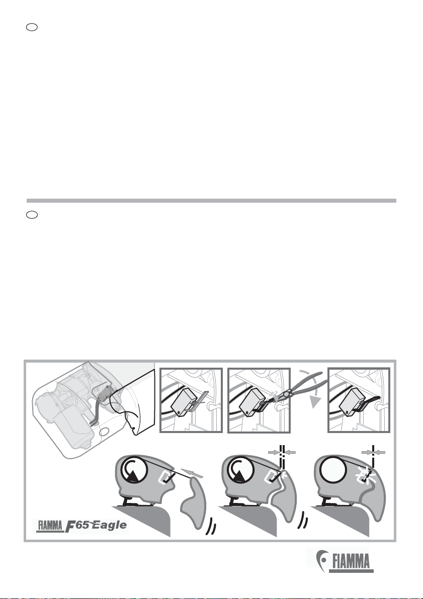
DE
Das Kabel des Sensor am Gelenkarm entlang einführen und mit der Führung P
blockieren. Am Gehäusekasten entlang bis zum Motor weiterführen und
dann das Kabel abschneiden.
Placez le fil du détecteur à l’intérieur du bras en le bloquant avec la gaine P.
Continuez le long du boîtier jusqu’au moteur et coupez le câble.
Insertar el Cable del Sensor a lo largo del brazo, bloqueándolo con la funda P,
seguir en el armazón hasta el motor y cortar el cable
Inserire il filo del Sensore lungo la sede del braccio bloccandolo con la guaina
P, seguire sul cassonetto fino al motore e tagliare il cavo.
Insert the wire of the sensor along the housing of the arm blocking it with
sheath P, go on to motor and then cut the cable.
MICRO
SWITCH
SISMIC
SENSOR E2
E1
P
E2
10 cm
ENGINE

13
®
®
9
Den Sensor im Innern der Frontblende positionieren und mit den
Schrauben befestigen.
Placez et fixez le détecteur à l’intérieur du bandeau frontal avec de la colle.
E2
E2
Position and fix the sensor , inside the lead bar with glue.E2
Poner y fiyar el Sensor en el interior del frontal con cinta adhesiva.
Posizionare e fissare il Sensore sull’interno del frontale con adesivo.
E2
E2
DE
EN
FR
ES
IT
10
E2
Q
E2
P

14
®
®
11
OK NO NO NO
SISMIC SENSOR
P
SISMIC
SENSOR
E2
DE
EN
FR
ES
IT
Um den SISMIC SENSOR anschliessen zu können, die Abdeckung öffnen
und das Kabel, welches von der Vermittlungsstelle hergeht, anschliessen. Den
Zylinder des Sensores regulieren, wobei der Zeiger nach oben positioniert
werden muss, die Abdeckung schliessen und alles dann mit beidseitigem
Klebestreifen oder Kleber an der Frontblende der Markise befestigen.
To connect the SISMIC SENSOR open the cover and connect the cable from
the controller. Adjust the cylinder of the sensor, positioning the arrow up, close
the lid and fix everything on the front bar of the awning with double sided tape
or glue.
Para conectar el SISMIC SENSOR abrir la tapa y conectar el cable de la
centralina. Ajustar el cilindro del sensor, colocando la flecha hacia arriba;
cerrar la tapa y fijar todo en la tapa frontal del toldo con cinta de doble cara o
pegamento.
Per collegare il SISMIC SENSOR aprire il coperchietto e collegare il cavo che
proviene dalla centralina. Regolare il cilindro del sensore, posizionando la
freccia verso l’alto; chiudere il coperchietto e fissare il tutto sul frontale della
veranda con il biadesivo o della colla.
Pour brancher le SISMIC SENSOR, ouvrez le petit couvercle et relier le câble
provenant du boîtier électronique. Régler le cylindre du capteur en plaçant la
flèche vers le haut. Fermer le petit couvercle et fixez le tout sur le bandeau
frontal du store avec du scotch double-face ou de la colle.
DE
EN
FR
ES
IT
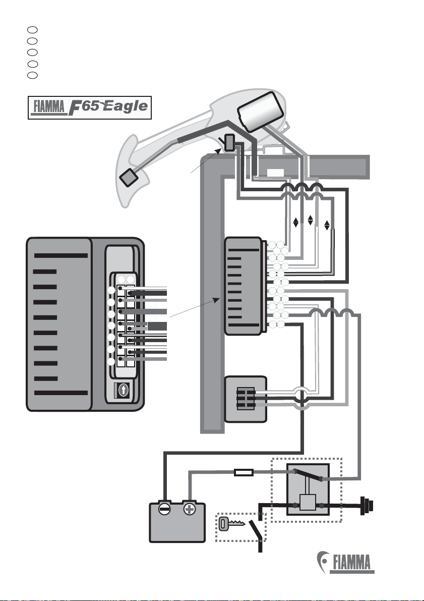
GRAFISCHE DARSTELLUNG DER ELEKTRISCHEN VERBINDUNG.
GRAPHIC REPRESENTATION OF THE ELECTRICAL CONNECTIONS
.
.
SCHÉMA DES BRANCHEMENTS ÉLECTRIQUES
REPRESENTACION GRAFICA DE LAS CONEXIONES ELECTRICAS.
RAPPRESENTAZIONE GRAFICA DEI COLLEGAMENTI ELETTRICI.
15
®
®
CONTROL UNIT
CONTROL UNIT
98155-070 rev.B
AB
1
3
4
2
5
6
7
SISMIC
SENSOR
MICRO
SWITCH
CONTROL
SYSTEM
Red
Red
Blue
Red
Purple
Purple/White
Black
Black
Black
Black
Orange
Orange/White
RELÈ
12 V 20A
1 FORM C
RELÈ
12 V 20A
1FORM C
86
85
87
87a 30
*
+12V
START
FUSE 16 AFUSE 16 A
O
E1
Black
Red
BATTERY
12V
Red
E2
Blue
RETRACT
EXTEND
A
1
A
2
A7
A6
B
B
B5
AB
44
6
1
A3
Red
Blue/Black
A5
CONTROL UNIT
98155-070 rev.B
ENGINE

ALLGEMEINE GEBRAUCHSANWEISUNG
Dieser Artikel funktioniert auf 12 V Achtung: Niemals an eine andere Spannung
verbinden.
Die Kabel werden nicht mitgeliefert. Es wird empfohlen, Kabel mit einem
Mindestdurchmesser von 1,5 mm² zu verwenden.
Nach Anbringung des elektrischen Systemes eine generelle Probe wie folgt
durchführen:
- Vergewissern Sie sich, dass die Markise, wenn sich der Schalter in der Position
EXTEND befindet, öffnet und das sich die Markise, wenn der Schalter in der Position
RETRACT befindet, schliesst; sollte das Gegenteil eintreten, muss die Polarität
umgekehrt werden.
-ö ü
ü
Die Verbindung des Mikroschalters zur Endkappe weder unterbrechen noch ändern.
Andernfalls erlischt die Gewährleistung.
Keine anderen Schalter, als den in der Ausstattung enthaltenen, verwenden.
Die Markise komplett ffnen. Daraufhin schliessen und pr fen, dass der Mikroschalter,
wenn gedr ckt, die Bewegung unterbricht. Sollte dies nicht erfolgen, dann laut
folgendem Schema (S.17) fortfahren.
GENERAL PRECAUTIONS
This product works on 12Vdc. Never connect it at different voltage.
The cables are not supplied. It is recommended to use cables minimum 1,5
.
After the electrical system has been installed, test the good functioning of it:
- Make sure that the awning opens with the switch in position and that it
closes when the switch is in position ;on the contrary, invert the polarity.
-
Do not disconnect or change the micro switch on the end cap. On the contrary, warranty
will be no longer valid.
Do not use different switches than the one supplied.
mm²
diameter
EXTEND
RETRACT
Fully open the awning and then close it again making sure that the micro switch stops
the movement if pressed in case this does not happen follow the next diagram
-
,; , .
INSTRUCTIONS GENERALES
Cet article fonctionne à 12Vdc. Ne la branchez jamais à une tension
différente.
Les câbles ne sont pas fournis. Nous vous conseillons des câbles de minimun
de diamètre.
Après avoir terminé l’installation électrique, effectuez un essai de fonctionnement
général, en procédant aux tests suivants :
- Assurez-vous que le store s’ouvre avec l’interrupteur en position EXTEND et qu’il se
ferme
avec l’interrupteur en position RETRACT. Dans le cas contraire, inverser la polarité.
-
Ne séparez ni changez le micro-interrupteur sur le cache, dans le cas contraire la
garantie ne sera pas considerée comme valable.
N’utilisez pas d’interrupteurs autres que ceux livrés de série.
1,5 mm²
Ouvrez complètement le store puis refermez-le en vérifiant que le micro-interrupteur
interrompt le mouvement quand on appuie dessus. Si ce n’est pas le cas, suivez les
consignes indiquées dans le schéma suivant.
DE
EN
FR
16
®
®
AVVERTENZE GENERALI
Questo prodotto funziona a 12Vdc. Non collegare mai una tensione diversa.
Per i cavi non forniti, si consiglia di utilizzare cavi di sezione minima 1,5 mm².
Dopo il montaggio del sistema elettrico, fare una prova generale di funzionamento
eseguendo i seguenti test:
-Assicurarsi che il tendalino si apra con l’interruttore in posizione EXTEND e si chiuda
con l’interruttore in posizione RETRACT; in caso contrario invertire la polaritá
all’ingresso del motore;
-Aprire completamente il tendalino e successivamente richiuderlo verificando che il
micro-switch interrompa il movimento, se premuto; in caso questo non avvenga, agire
come da schema successivo.
Non scollegare ne’ cambiare il micro-switch sulla spalletta. In caso contrario, la
garanzia non è valida.
Non utilizzare interruttori diversi da quello in dotazione.
ADVERTENCIAS GENERALES
Este producto funciona a 12 Vdc. No conectar nunca a una tensión de funcionamiento
diferente.
Los cables no son suministrados de serie. Se aconseja utilizar los cables de diámetro
mínimo 1,5 mm² y.
Después del montaje del sistema eléctrico, hacer una prueba general de
funcionamiento:
- asegurarse que el toldo se abre completamente con el interruptor en posición
EXTEND y que se cierre con el interruptor en posición RETRACT; en caso
contrario invertir la polaridad en la entrada del motor.
-á
No desconectar ni cambiar el microswitch sobre la contratapa.
En caso contrario, la garantía no es más válida.
No usar interruptores diferentes de los suministrados de serie.
Abrir completamente el toldo y cerrarlo de nuevo, asegur ndose de que el micro-
interruptor detenga el movimiento, si se pulsa; en caso de que esto no suceda, seguir el
esquema siguiente.
ES
IT
17
®
®
123
MICRO-SWITCH
18
®
®
DE
EN
FR
ES
IT
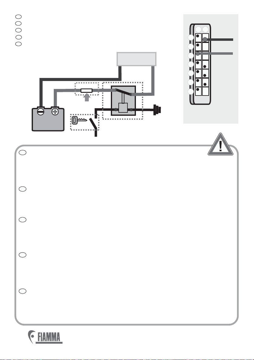
Anschluss an die 12 V Stromzufuhr.
Supply connection 12V.
Branchement d’alimentation 12V.
Conexión de alimentación 12V.
Collegamento alla alimentazione 12V.
CONTROL
AB
1
3
4
2
5
6
7
Red
Black
UNIT
Black
RELÈ
12 V 20A
1 FORM C
RELÈ
12 V 20A
1FORM C
86
85
87
87a 30
*
+12V
START
FUSE 16 AFUSE 16 A
Red
BATTERY
12V
CONTROL
UNIT
DE
EN
FR
ES
IT
Es wird empfohlen, die elektrische Verbindungen laut dem Schema
auszuführen. Sobald Sie den Zündschlüssel drehen, trennt das Relais
(*nicht mitgeliefert) den Strom von dem elektrischen Motor der Markise, um somit
ein versehentliches Öffnen der Markise während der Fahrt zu verhindern.
Eine Sicherung (16 A) an der Stromzufuhr vorsehen.
We advice to make the electric connections as indicated on the diagram. When the
ignition key is turned, the relay (*not supplied) cuts off the current to the electric
motor, to avoid any accidental opening of the awning when the vehicle is moving.
ea e e( A) n e r y.Provid protectiv fus 16 o th powe suppl
Nous vous conseillons d’effectuer les branchements électriques comme indiqué sur
le schéma. Après avoir tourné la clé de contact en position de mise en route, le
relais (*non fourni) coupe le courant du moteur électrique afin d’éviter toute
ouverture accidentelle du store quand le véhicule est en mouvement.
Prévoir un fusible de protection (16A) sur l’alimentation.
Aconsejamos efectuar las conexiones eléctricas como en el esquema indicado,
una vez girada la llave de puesta en marcha en la posición de encendido, el relais
(*no suministrado de serie) corta la corriente al motor eléctrico, para evitar cualquier
apertura casual del toldo con el toldo en movimento.
Se necesita un fusible de protecciòn (16A) sobre la alimentaciòn.
Si consiglia di effettuare i collegamenti elettrici come da schema indicato. Una volta
ruotata la chiave di avviamento in posizione di accensione, il relè (*non fornito)
taglia la corrente al motore elettrico, così da evitare qualsiasi apertura accidentale
del tendalino a mezzo in movimento. Prevedere un fusibile di protezione (16A)
sull’alimentazione.

DE
EN
FR
ES
IT
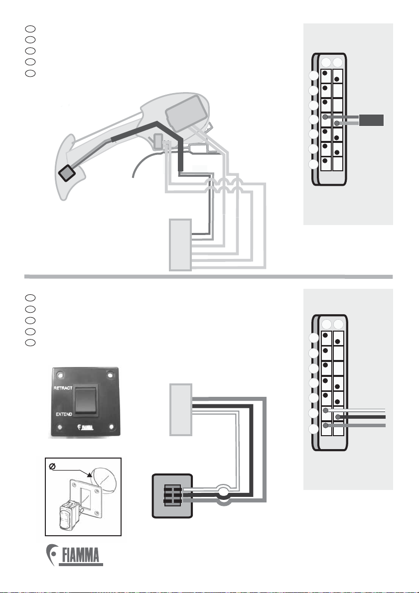
Motorverbindung.
Engine connection.
Branchement du moteur.
Conexión del motor.
Collegamento del motore.
DE
EN
FR
ES
IT
Mikroswitchverbindung.
Micro switch connection.
Branchement du micro-interrupteur.
Conexión del micro interruptor.
Collegamento del micro switch.
Purple
1
3
4
2
5
6
7
ABPurple/white
AB
1
3
4
2
5
6
7
Blue/black
Black
CONTROL
UNIT
CONTROL
UNIT
MICRO
SWITCH
Red
Black
Black
MOTOR
Red
Blue/Black
CONTROL
UNIT
®
®
19
Blue
Red
Purple
Blue
Purple/White
Red
CONTROL
UNIT
ENGINE
DE
EN
FR
ES
IT
Sismic Sensor Verbindung.
Connection of the sismic sensor.
Branchement du sismic sensor.
Conexión del sismic sensor.
Collegamento del sismic sensor.
DE
EN
FR
ES
IT
Control System Verbindung.
Control system connection.
Branchement du control system.
Conexión del control system.
Collegamento del control system.
CONTROL
UNIT
AB
1
3
4
2
5
6
7
CONTROL
UNIT
AB
1
3
4
2
5
6
7
Blue
Red
CONTROL
UNIT
E2SISMIC
SENSOR
RETRACT
EXTEND
CONTROL
SYSTEM
Orange
Orange/White
O
Black
CONTROL
UNIT
20
®
®
O
CONTROL SYSTEM
45 mm45 mm
Table of contents
Other FLAMMA Accessories manuals


