Flare Fireplaces Flare Front 30-100" User manual

INSTALLER: Leave this manual with appliance
CONSUMER: Retain this manual for future reference.
Installation & servicing of this appliance MUST be performed by a qualified NFI certified technician.
MASSACHUSETTS: The piping and final gas connection must be performed by a licensed plumber gas fitter in
the state of Massachusetts.
Modern Gas Fireplaces –Linear Fireplaces
FLARE FIREPLACES | POWER VENT INSTALLATION MANUAL
[SIT CS7 SYSTEM] HIGH VOLTAGE VERSION 6.0
NOTICE
WARNING: IF THE INFORMATION IN THESE INSTRUCTIONS
ARE NOT FOLLOWED EXACTLY, A FIRE OR EXPLOSION MAY
RESULT , CAUSING PROPERTY DAMAGE, PERSONAL INJURY,
OR LOSS OF LIFE.
-DO NOT STORE OR USE GASOLINE OR OTHER
FLAMMABEL VAPORS AND LIQUIDS IN THE VICINTY OF
THIS OR ANY OTHER APPLIANCE.
-WHAT TO DO IF YOU SMELL GAS?
•DO NOT TRY TO LIGHT ANY APPLIANCE
•DO NOT TOUCH ANY ELECTRICAL SWITCH; DO NOT
USE ANY PHONE IN YOUR BUILDING.
•IMMEDIATELY CALL YOUR GAS SUPPLIER FROM A
NEIGHBOR’S PHONE. FOLLOW THE GAS SUPPLIERS’
INSTRUCTIONS.
•IF YOU CANNOT REACH YOUR GAS SUUPLIER, CALL
THE FIRE DEPARTMENT.
-INSTALLATION AND SERVICE MUST BE PERFORMED BY A
QUALIFIED INSTALLER, SERVICE AGENCY OR GAS
SUPPLIER.

2 | P a g e
CONTENTS
SAFTEY INFO AND WARNINGS ..........................................................................................................................................................................3
FLARE FIREPLACES –FRAMELSS IN EVERY WAY .................................................................................................................................................4
SAFETY ............................................................................................................................................................................................................4
MANUAL MODEL LIST & INFORMATION............................................................................................................................................................4
POWER VENTING OVERVIEW............................................................................................................................................................................5
POWER VENT DRAWINGS.................................................................................................................................................................................5
HORIZONTAL END OF LINE POWER VENT DRAWING........................................................................................................................................................5
HORIZONTAL END-OF-LINE POWER VENT FRAMING DIMENSIONS .................................................................................................................................6
HORIZONTAL POWER VENT MOUNTING AND FINISHING FLANGES.................................................................................................................................7
HORIZONTAL POWER VENT PARTS LIST............................................................................................................................................................................8
VERTICAL END OF LINE POWER VENT DRAWING..............................................................................................................................................................9
VERTICAL POWER VENT PARTS LIST................................................................................................................................................................................11
IN-LINE POWER VENT DRAWING ....................................................................................................................................................................................12
IN-LINE POWER VENT PARTS LIST ...................................................................................................................................................................................13
VENT ADAPTER CONVERSION ......................................................................................................................................................................... 14
CLEARANCES TO POWER VENT ....................................................................................................................................................................... 17
CLEARANCES TO VENT PIPE............................................................................................................................................................................ 17
MINIMUM CLEARANCE TO COMBUSTIBLES FROM VERTICAL VENT .................................................................................................................. 18
MULTIPLE VERTICAL TERMINATION POINTS .................................................................................................................................................... 19
MULTIPLE HORIZONTAL TERMINATION POINTS...............................................................................................................................................19
VENT TERMINATION CLEARANCES.................................................................................................................................................................. 20
VENT RESTRICTOR SETUP ............................................................................................................................................................................... 21
VENT RESTRICTOR TROUBLESHOOTING .......................................................................................................................................................... 21
POWER VENT ELECTRICAL CONNECTION......................................................................................................................................................... 22
SIT PROFLAME 2 CONNECTIONS .....................................................................................................................................................................24
FIREPLACE ELECTRICAL DRAWING (WITH POWER VENT –SIT PROFLAME II).................................................................................................................25
POWER VENT ELECTRICAL WIRING DRAWING .................................................................................................................................................26
DOUBLE GLASS BOARD AND FAN SWITCHES ..................................................................................................................................................................27
STARTING UNIT.............................................................................................................................................................................................. 28
VENTING .......................................................................................................................................................................................................28
CONNECTING 3X5 PIPE...................................................................................................................................................................................30
REPLACEMENT PARTS .................................................................................................................................................................................... 31
APPENDIX......................................................................................................................................................................................................32
YEARLY SERVICE REQUIREMENTS.................................................................................................................................................................... 32
PILOT MAINTENANCE......................................................................................................................................................................................................33
BURNER MAINTENANCE .................................................................................................................................................................................................33
VENT MAINTENANCE ......................................................................................................................................................................................................33
DOUBLE GLASS FANS.......................................................................................................................................................................................................33
MAINTENANCE LOG....................................................................................................................................................................................... 34
WARRANTY POLICY ........................................................................................................................................................................................ 35
3 | P a g e
SAFTEY INFO AND WARNINGS
•
Series, in
Canada.
•This appliance is only for use with the type(s) of gas indicated on the rating plate. A conversion kit is supplied
with the appliance.
•
At High Altitude
•
from hot surfaces
•
•
•
result causing property damage,
personal injury, or loss of life.
•
supplier
.
•
appliance.
WARNING!

4 | P a g e
FLARE FIREPLACES –FRAMELSS IN EVERY WAY
Flare Fireplaces is where innovation, quality and luxury come together to form new ideas. By combining superior raw materials,
contemporary design, creative technology, and a frameless way of thinking, we have created a full line of direct-vent fireplaces
that are luxurious, simple to operate and efficient. Our Fireplaces are distinguished by their clean design, superior build quality
and unique features.
SAFETY
CSA CERTIFICATION
All our fireplaces are tested and have been certified to meet stringent CSA guidelines, ensuring optimum quality, safety, and
efficiency. All our fireplaces have been certified and tested to work with Natural Gas or Propane. Certification Information:
ANSI Z21.88/CSA 2.33-2014- Vented Gas Fireplace Heaters
CSA CLASSES:
CLASS 2901 84 / CLASS 2901 04
MANUAL MODEL LIST & INFORMATION
The Following manual should be used for Flare Fireplaces Models:
•Flare Front 30-100 “
•Flare See-Through 30-100”
•Flare Corner Right and Left 30-100”
•Flare Double Corner 30-100”
•Flare Room Definer 45-100”
To simplify the installation and operation, all models above share the same gas valve system, remote, gas connection, glass type.
All warnings and instructions apply to all models. Flare Fireplaces Power Vent system must only be connected to M&G 3x5
venting system. For detailed chimney installation information please use the M&G DuraVent direct vent installation manual:
https://www.duravent.com
Installation
MUST
comply with local,regional, state and national codesand regulations.Consult insurance carrier,
local building
inspector, fire officials or authorities having jurisdiction over restrictions, installation inspection and
permits.
This installation mustconform to local codes. In the absence of local codes, you must comply with the
National Fuel Gas Code,
ANSIZ223.1-Latest Edition inthe U.S.A.andtheCAN/CGAB149 Installation Codes in Canada.
Improper installation, adjustment,alteration, serviceor maintenance can cause injury or property damage. For
assistance or
additional information,consulta qualified service technician, service agencyor your dealer.

5 | P a g e
POWER VENTING OVERVIEW
In the event of a vent route that is unsupported based on the Gravity Vent Tables shown in the Flare Install Manual, Flare
Fireplaces may use a power vent to accommodate any extremely long, or negative degree venting routes. The 3 power vent
options allow the fireplace to operate in vent conditions that would not be possible without the powered fan. With a power-vent
you can install a 90-elbows right off the top of the fireplace. When using the power vent system, it is critical that the vent path
remain completely sealed for the power vent system to operate. The vent length and restrictor level should be set based on
number of feet, number of elbows, and the vent termination.
The system is designed and tested with DuraVent 3x5 gasket direct vent pipes. It is critical for the safety and operation of the
system to use the DuraVent 3x5 gasket system. See the link below for a DuraVent catalog & vent parts with part numbers:
https://www.DuraVent.com/docs/product/CVS_Catalog.pdf
All three Flare Power Vent systems can be installed to include 8 elbows and run up to 100ft vent run.
-A minimum length of 12ft venting is required between the Fireplace and the PV, Flare Fireplaces sizes 30”-70”. A minimum
length of 15ft,Flare sizes 80”-100”, is required between the fireplace and the PV.
-Elbows, whether 45 or 90 degrees, do not count towards the minimum distance requirements.
-Do not install any Power Vent system if the minimum length is below listed above. The three Power Vent systems can be
installed with a maximum of 5ft vent run below the fireplace.
-Do not install any of the Flare Power Vent fans inside the fireplace cavity, as this increases the risk of overheating
-Do not snake 3x5 vent pipe within cavity to achieve minimum length, as this will lead to increased heat buildup.
POWER VENT DRAWINGS
HORIZONTAL END OF LINE POWER VENT DRAWING

6 | P a g e
HORIZONTAL END-OF-LINE POWER VENT FRAMING DIMENSIONS
ROUGH OPENING CUT-OUT DIMENSIONS: 13 ½ W x 14 ½ H

7 | P a g e
HORIZONTAL POWER VENT MOUNTING AND FINISHING FLANGES
8 | P a g e
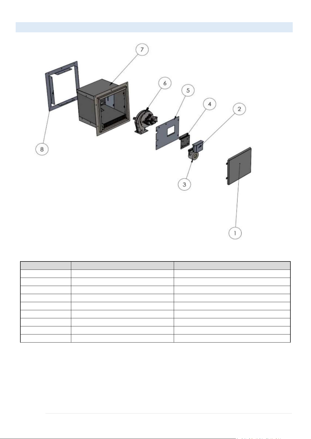
HORIZONTAL POWER VENT PARTS LIST
HORIZONTAL POWER VENT PART LIST:
ITEM NUMBER
PART Name
DESCRIPTION
1
W-F-08
PV External Cover
2
W-F-14
PV Board Cover
3
Draft Switch
HUBA control to measure fan pressure
4
Elec. Holder
Electrical wiring holder
5
Motor inner cover
Internal cover motor
6
Exhaust Blower
Main Exhaust Fan
7
Housing of Exhaust Blower
PV Whole Block
8
W-F-10
Bracket for fixing PV hole.
9
Exhaust Blower Carrier
Exhaust Outlet Holder

9 | P a g e
VERTICAL END OF LINE POWER VENT DRAWING
ROOF
Exhaust Outlet
110V AC Cable

10 | P a g e
11 | P a g e
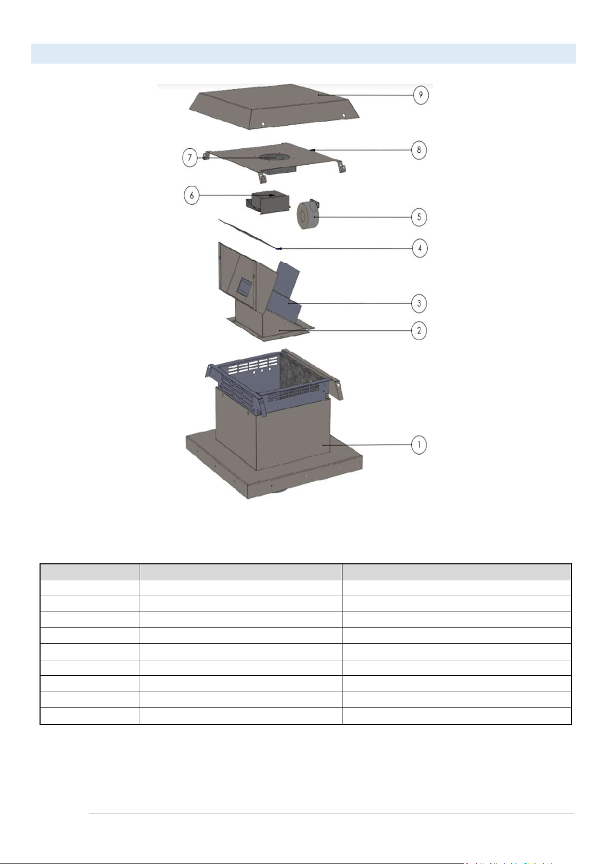
VERTICAL POWER VENT PARTS LIST
VERTICAL POWER VENT PARTS LIST:
ITEM NUMBER
PART NUMBER
DESCRIPTION
1
Housing of Exhaust Blower - Vertical
The whole block for vertical power vent
2
Fan | 03 + 04
Main Fan Holder
3
Exhaust Blower
Main Exhaust Fan
4
Fan | 08
Inner upper cover for exhaust outlet
5
Draft Switch
HUBA Control for pressure measuring
6
Electric Board
Electrical Board Cover
7
Fan
Cooling Fan
8
Fan | 12
Cooling Fan Holder
9
Fan | 06
External Upper Cover

12 | P a g e
IN-LINE POWER VENT DRAWING
PLEASE NOTE THAT THE INLINE POWER VENT MUST BE MOUNTED TO A STRUCTURE AND CANNOT JUST FLOAT
USING THE VENT PIPE
13 | P a g e
IN-LINE POWER VENT PARTS LIST
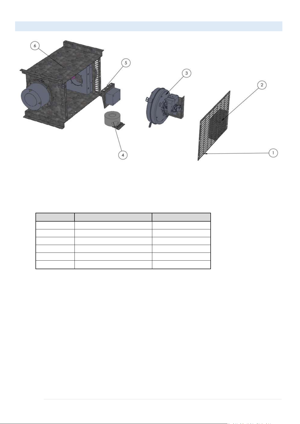
IN-LINE POWER VENT PARTS LIST:
ITEM NUMBER
PART Name
DESCRIPTION
1
FanExNet
External Cover
2
C-Fan
Cooling Fan
3
Exhaust Blower
Main Fan
4
Draft Switch
(HUBA Control) Pressure Switch
5
FanExDish
Electrical Wiring Holder
6
House of Exhaust Blower In-Line
In-Line Whole Block
Part List
ITEM NUMBER
PART NUMBER
DESCRIPTION
1
FanExNet
External Cover
2
Fan
Cooling Fan
3
Exhaust Blower
Main Fan
4
Draft Switch
HUBA Control
5
FanExDish
Electronic Board Holder
6
House of Exhaust Blower In-Line
In-Line Whole Block
14 | P a g e
VENT ADAPTER CONVERSION
In the event a fireplace is shipped with a standard collar and needs to be converted to support a CVS 3x5
collar, follow the steps below:
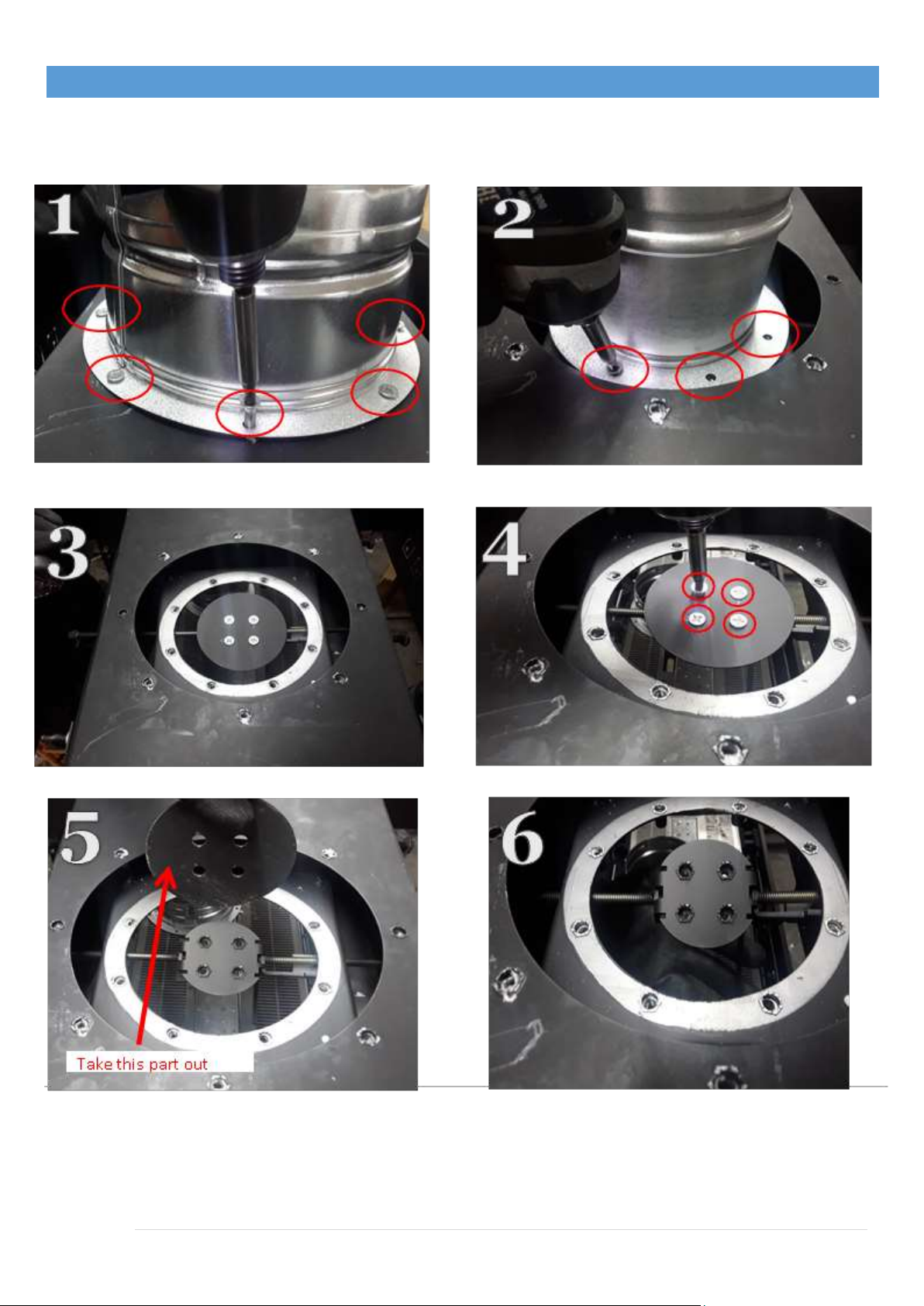
1. Remove the 4x6/5x8 Vent adapter from the top of the fireplace as shown in the pictures below:
15 | P a g e
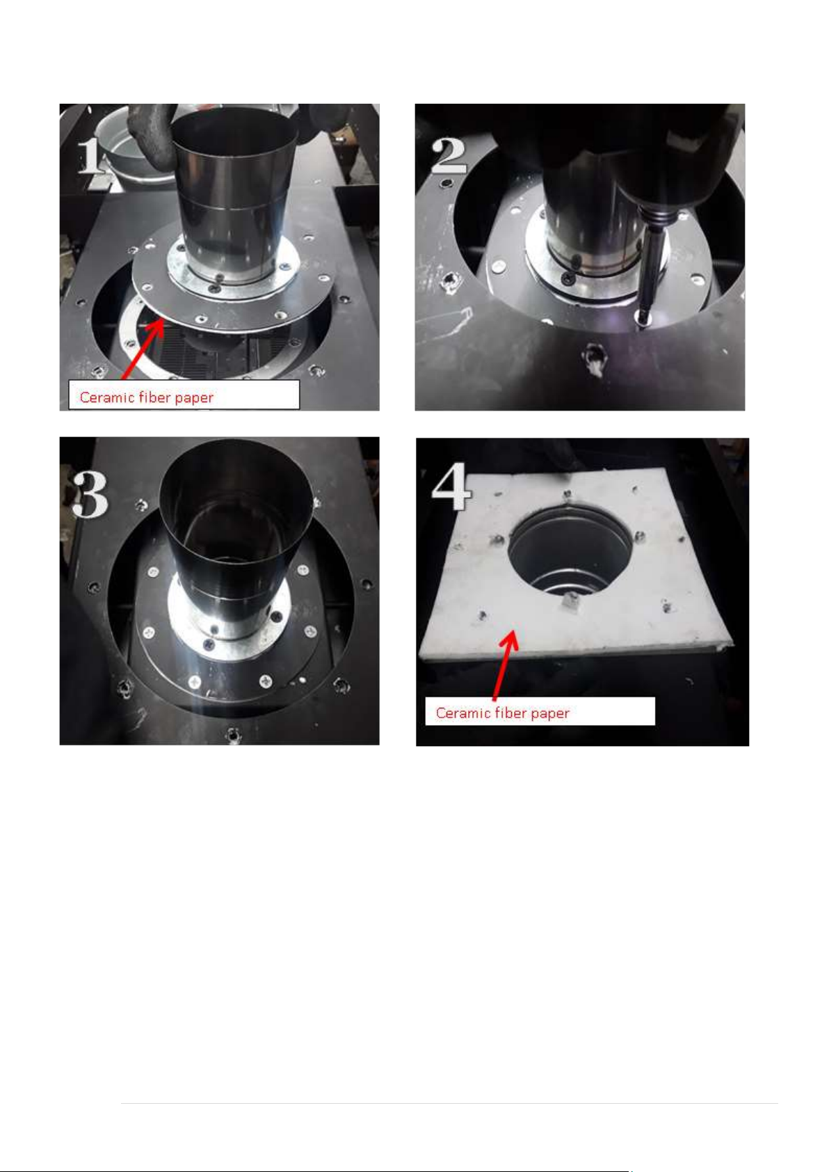
2. Install 3x5 Vent adapter:
a. Attach the 3inch Female (inner) part first as shown in step1, then tighten the screws as shown in step 2.
b. Use 3mm ceramic fiber paper to isolate the vent adapter as shown in steps 1 and 4.
c. Step 4 shows the 5-inch male part base after using the ceramic fiber paper

16 | P a g e
3. Place the 5 Inch Male Adapter in place and tighten down screws to secure to unit.

17 | P a g e
CLEARANCES TO POWER VENT
This section describes the Flare Fireplaces Power Vent system clearance dimensions for building materials.
1. Clearance diagram is displayed below.
a. 24-inch clearance in front of access panel (Inline only) for service and removal.
b. 12-inch clearance above axillary fan for cooling (if axillary fan is part of fan box assembly).
c. 2-inch clearance on Flare Fireplaces Power Vent sides and bottom.
2. Access Panel for Flare Fireplaces Power Vent –Inline PV Only
a. Minimum 18-inch x 18-inch access panel required for service.
b. The Flare Fireplaces Power Vent must be in an area with a minimum 8 cubic feet of free air space to keep
the component operating temperature cool. In addition, the access panel must be louvered to allow for a
minimum of 75 sq. inches of free air space.
3. Flare Fireplaces Power Vent Mounting
a. Mount the Flare Fireplaces Power Vent per local code requirements, and follow the manufacturer’s
instructions for securing venting
CLEARANCES TO VENT PIPE
Clearance between the vent pipe and combustible materials must be maintained at 3” inches top and 1”
for side and below. Maintain the same clearance from the power vent box to any combustible materials.
a. HORIZONTAL VENT CLEARANCES: A minimum clearance of 3” (76mm) to the top and 1” (51mm) to
the sides and bottom of the vent pipe on all horizontal runs to combustibles is required.
b. VERTICAL VENT CLEARANCES: A minimum of 1” (25mm) all around the vent pipe on all vertical runs
to combustibles is required except for clearances in appliance enclosure.
18 | P a g e
MINIMUM CLEARANCE TO COMBUSTIBLES FROM VERTICAL VENT
POWERVENT UNIT MUST BEINSTALLED BYA QUALIFIED INSTALLERINACCORDANCE WITH THESE INSTRUCTIONS. CAUTION! FAILURE TOINSTALL,
OPERATE, AND MAINTAIN THE POWER VENTING SYSTEM INACCORDANCE WITH MANUFACTURER'S
INSTRUCTIONS WILL RESULTINCONDITIONS
WHICH MAYPRODUCE BODILY INJURY AND/OR PROPERTYDAMAGE

19 | P a g e
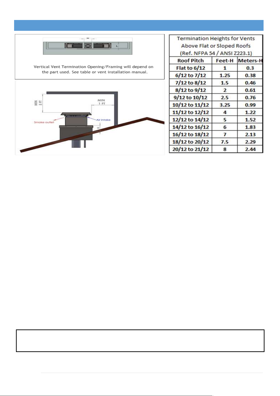
MULTIPLE VERTICAL TERMINATION POINTS
•If using decorative cap cover/s, this distance may need to be increased. Refer to the installation
instruction supplied the decorative cap cover.
•In a staggered installation with both gas and wood or fuel oil termination, the wood or fuel oil
termination cap must be higher than.
MULTIPLE HORIZONTAL TERMINATION POINTS
Exhaust Outlet

20 | P a g e
VENT TERMINATION CLEARANCES
^ Vent shall not terminate directly above a sidewalk or paved driveway, located between two single
family dwellings, serving both dwellings.
** Only permitted if veranda, porch, deck, or balcony is fully open on a minimum of 2 sides beneath the
door.
*Clearance in accordance with local installation codes and the requirements of the gas supplier.
*As specified in CGA B149 Installation Codes, note local Codes or Regulation may require different
clearances.
*For U.S.A. Installations follow the current National Fuel Gas Code, ANSI Z223.1
*** Horizontal vent termination minimum clearance to adjacent structure or fence is 48”.
**** Minimum 24” horizontal clearance to any surface (such as an exterior wall) for vertical terminations.
A
^12 inches (30 cm) min.
Clearances above grade, veranda, porch, deck, or balcony
B
**12 inches (30 cm) min.
Clearance to window or door that may be opened
C
12 inches (30 cm) min.
Clearance to permanently closed window recommended to prevent
condensation on window
D
12 inches (30 cm) min.
18 inches (46cm) for vinyl surfaces
Vertical clearance to ventilated soffit located above the terminal within
a horizontal distance of 2 feet (60 cm) from the edge of the terminal
E
12 inches (30 cm) min.
18 inches (46cm) for vinyl surfaces
Clearance to unventilated soffit.
F
6 inches (15 cm) min.
Clearance to outside corner
G
6 inches (15 cm) min.
Clearance to inside corner
H
3 feet (90 cm) min.
*Not to be installed above a meter/regulator assembly within 3 feet (90 cm)
horizontally from the centerline of the regulator
I
3 feet (90 cm) min.
Clearance to service regulator vent outlet
J
*12 inches (30 cm) min.
Clearance to non-mechanical air supply inlet to building or the combustion air
inlet to any other appliance
K
*6 feet (1.8 m) min.
Clearance to a mechanical air supply inlet
L
***7 feet (2.1 m) min.
Clearance above paved sidewalk or a paved driveway located on public
property
M
****20 inches (51 cm) min.
Clearance under veranda, porch, deck, or balcony
Other manuals for Flare Front 30-100"
1
This manual suits for next models
40
Table of contents


