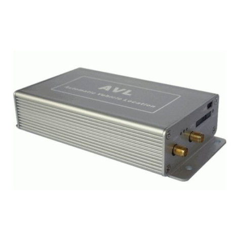
FleetData FD420-GSM User manual

FleetData Pty Ltd yABN 85 084 389 257.
P.O. Box 886 Mt Ommaney QLD, Australia 4074
Telephone: +61-7-3712-0444 yFax: +61-7-3712-0555
© Copyright 2006 FleetData Pty Ltd. All Right Reserved. Page 1of 3
FD420-GSM &FD420-CDMA
Mobile Tracking and Telemetry Unit
DESCRIPTION
The FD420-GSM Online Tracking Module is an intelligent GPS to GSM device with logging
capabilities. The device provides 4 digital inputs for recording specific asynchronous events and 2
digital outputs for controlling specific devices.
When not within range of a GSM network device the FD420-GSM can log up to 32,000 points of
tracking information for later retrieval using non-volatile circular buffer memory.
CONTENTS
The FD420-GSM is supplied with the following items:
FD420-GSM device. GPS Antenna, 3V Active.
Interface and power cable. 1A 3AG fuse and fuse holder.
This information sheet…
SPECIFICATIONS
Operating voltage: 12VDC +/-20% or 24VDC +/-20%
Current consumption: 400mA MAX. 20mA when ignition off (if enabled)
Operating frequency: GSM (or CDMA) Network
FD420-GSM INSTALLATION INFORMATION
FD420-GSM CONNECTION DIAGRAM
Assembled Unit

FleetData Pty Ltd yABN 85 084 389 257.
P.O. Box 886 Mt Ommaney QLD, Australia 4074
Telephone: +61-7-3712-0444 yFax: +61-7-3712-0555
© Copyright 2006 FleetData Pty Ltd. All Right Reserved. Page 2of 3
FD420-GSM CONNECTION DETAILS
WIRE COLOUR DESCRIPTION
POWER
RED +12VDC or +24VDC (note 1 & 5)
BLACK Chassis Ground
INPUTS
YELLOW INPUT #1 – 12V/24V Switched Accessories Power (note 2,4)
BLUE INPUT #2 – Customer use (note 3,4)
BROWN INPUT #3 – Customer Use (note 3,4)
GREEN INPUT #4 – Customer Use (note 3,4)
OUTPUTS
PURPLE OUTPUT #1 - Customer Use (note 3,4)
ORANGE OUTPUT #2 - Customer Use (note 3,4)
WARNING: DO NOT CONNECT POWER UNTIL
ALL OTHER CONNECTIONS ARE IN PLACE
NOTES:
1. Connection to 12VDC must be fused using supplied 1 amp automotive fuse and fuse
holder.
2. Switched Accessory Power must be connected to input #1 if the smart power- save
feature is enabled. Please consult your software manual for enabling this feature.
3. The use of these inputs is user selectable. They are general purpose inputs that
must be pulled to 12VDC to change their state otherwise they are read as off.
4. The inputs are sampled over a 1 second period, so for a state change to be
recorded the event change must be present for at least 1 second.
5. The unit is suitable for connection to either a 12VDC or 24VDC system.
CONNECTING THE ANTENNAS
The supplied GPS antenna must be connected to the FD420-GSM correctly in order to obtain a
valid satellite fix. The following must be considered when connecting the antenna.
1. Connect the GPS antenna to the gold FD420-GSM labelled GPS.
2. Connect an appropriate GSM antenna to the gold FD420-GSM labelled MDM.
3. Finger tighten the screw connectors to a positive stop.
Do not over tighten
GPS ANTENNA PLACEMENT
The position of the antenna mounting is crucial to the optimal performance of the GPS receiver.
The GPS antenna must be mounted in such a way as to ensure it has as much an uninterrupted
view of the sky as possible. The rear parcel shelf or front dash board of a sedan may be suitable.
The base of the antenna is magnetic thus it can be mounted external to the vehicle. Be careful
while laying the cable not to crease, cut, twist or kink the cable as this may break the internal
conductors or significantly affect its operation.

FleetData Pty Ltd yABN 85 084 389 257.
P.O. Box 886 Mt Ommaney QLD, Australia 4074
Telephone: +61-7-3712-0444 yFax: +61-7-3712-0555
© Copyright 2006 FleetData Pty Ltd. All Right Reserved. Page 3of 3
The antenna plane should be parallel to the geographic horizon and must have a full view of the
sky ensuring a direct line-of-sight with as many visible satellites as possible.
DO… …
do
mount the GPS antenna where it will see the most sky.
…
do
mount the antenna horizontal.
…
do
mount the antenna outside and on the vehicles roof where possible.
…
do
mount the antenna in an area with a good ground plane. A suitable ground
plane should provide for at least 15cm of metal in all directions.
DO NOT…
…
do no
mount the GPS antenna where it will be on an angle. It should be mounted
horizontal to see as much of the sky as possible.
t
tttt
tt
…
do no
kink or tightly wrap excess cable or
…
do no
pinch or trap cable when refitting trim to the vehicle.
…
do no
over tighten the GPS antenna. Tightening by hand is normally adequate.
…
do no
place the antenna close to other electronic equipment such as engine
management and control systems.
…
do no
place or mount the antenna where it will be covered or blocked by metal.
…
do no
mount antennas where they are close to people (> 30cms).
ADDITONAL NOTES…
… Fibreglass airfoils on trucks and Taxis can attenuate the GPS signal.
… Some automotive windscreens have a metallic coating. GPS reception in such cars
may not be possible. Sometimes there is a small section spared for GPS and mobile
phone antennas behind the rear view mirror.
EXAMPLES OF ANTENNA PLACEMENT
Recommended Antenna Placement Suitable but not ideal Antenna Placement
Performance may be degraded.
This placement gives a clear view of the sky and
provides the antenna with a good ground plane. Window and roof reduce GPS signal and
obstruct the sky view.
Fibreglass airfoil attenuates the GPS signal.
This manual suits for next models
1
Table of contents
