FLENDER Zapex ZWBT User manual

FLENDER COUPLINGS
ZWBT, ZWBG, ZWB, ZWH, ZWHD
Operating instructions 3502 en
Edition 10/2017
ZAPEX
- - - - - - - - - - - - - - - - - - - - - - - - - - - - - - - - - - - - - - - - - - - - - - - - - - - - - - - - - - - - - -
- - - - - - - - - - - - - - - - - - - - - - - - - - - - - - - - - - - - - - - - - - - - - - - - - - - - - - - - - - - - - -
- - - - - - - - - - - - - - - - - - - - - - - - - - - - - - - - - - - - - - - - - - - - - - - - - - - - - - - - - - - - - -
- - - - - - - - - - - - - - - - - - - - - - - - - - - - - - - - - - - - - - - - - - - - - - - - - - - - - - - - - - - - - -
flender.com


FLENDER COUPLINGS
Operating instructions
ZAPEX
3502 en
ZWBT, ZWBG, ZWB, ZWH, ZWHD
Edition 10/2017
Translation of the original operating instructions
T
echnical data
Spare parts,
customer service
Maintenance
and repair
Faults, causes
and remedy
Operation
Start-up
Fitting
T
echnical description
T
ransport and storage
Safety instructions
General notes
1
11
10
9
8
7
6
5
4
3
2
Flender GmbH
Alfred-Flender-Straße 77
46395 Bocholt
GERMANY
Document number: 3502 en
10/2017 Subject to alterations
Copyright © Flender GmbH 2017
All rights reserved
Legal notes
Warning note concept
This manual comprises notes which must be observed for your personal safety and for preventing material
damage. Notes for your personal safety are marked with a warning triangle or an "Ex" symbol (when applying
Directive 2014/34/EU), those only for preventing material damage with a "STOP" sign.
WARNING! Imminent explosion!
The notes indicated by this symbol are given to prevent explosion damage.
Disregarding these notes may result in serious injury or death.
WARNING! Imminent personal injury!
The notes indicated by this symbol are given to prevent personal injury.
Disregarding these notes may result in serious injury or death.
WARNING! Imminent damage to the product!
The notes indicated by this symbol are given to prevent damage to the product.
Disregarding these notes may result in material damage.
NOTE!
The notes indicated by this symbol must be treated as general operating information.
Disregarding these notes may result in undesirable results or conditions.
WARNING! Hot surfaces!
The notes indicated by this symbol are made to prevent risk of burns due to hot surfaces
and must always be observed.
Disregarding these notes may result in light or serious injury.
Where there is more than one hazard, the warning note for whichever hazard is the most serious is always used.
If in a warning note a warning triangle is used to warn of possible personal injury, a warning of material damage
may be added to the same warning note.
Qualified personnel
The product/system to which this documentation relates may be handled only by persons qualified for the work
concerned and in accordance with the documentation relating to the work concerned, particularly the safety and
warning notes contained in those documents.
Qualified personnel must be specially trained and have the experience necessary to recognise risks associated
with these products and to avoid possible hazards.
Proper use of Flender products
Observe also the following:
Flender products must be used only for the applications provided for in the catalogue and the relevant technical
documentation. If products and components of other makes are used, they must be recommended or approved
by Flender. The faultfree, safe operation of the products calls for proper transport, proper storage, erection,
assembly, installation, startup, operation and maintenance. The permissible ambient conditions must be
adhered to. Notes in the relevant documentations must be observed.
Trade marks
All designations to which the registered industrial property mark ® is appended are registered trademarks of
Flender GmbH. Other designations used in this document may be trademarks the use of which by third parties
for their own purposes may infringe holders’ rights.
Exclusion of liability
We have checked the content of the document for compliance with the hard and software described.
Nevertheless, variances may occur, and so we can offer no warranty for complete agreement. The information
given in this document is regularly checked, and any necessary corrections are included in subsequent editions.
Explanation regarding Machinery Directive 2006/42/EC
The couplings described here are “components” in accordance with the Machinery Directive and do not require
a declaration of incorporation.

5
ZAPEX 3502 en
Operating instructions 10/2017
Contents
1. Technical data 7.....................................................
1.1 Types ZWBT and ZWBG 7.............................................................
1.2 Type ZWB 9.........................................................................
1.3 Types ZWH and ZWHD 11..............................................................
2. General notes 13.....................................................
2.1 Introduction 13........................................................................
2.2 Copyright 13..........................................................................
3. Safety instructions 14.................................................
3.1 Obligations of the user 14...............................................................
4. Transport and storage 15.............................................
4.1 Scope of supply 15....................................................................
4.2 Transport 15..........................................................................
4.3 Storage of the coupling 15..............................................................
4.3.1 Storage of the coupling parts 15.........................................................
4.3.2 Storage of the DUO sealing rings 15......................................................
4.3.2.1 General 15............................................................................
4.3.2.2 Storage area 15.......................................................................
5. Technical description 16..............................................
5.1 General description 16.................................................................
5.1.1 Types ZWBT, ZWBG, ZWB 16..........................................................
5.1.2 Types ZWH and ZWHD 17..............................................................
6. Fitting 18.............................................................
6.1 Instructions for applying the finished bore and fitting the axial retaining means,
set screws and balancing 18............................................................
6.1.1 Finished bore for parallel-key connection 18...............................................
6.1.1.1 Parallel keyway 19.....................................................................
6.1.2 Axial securing in case of parallel-key connection 19.........................................
6.1.3 Set screws in case of parallel-key connection 20...........................................
6.1.4 Balancing 22..........................................................................
6.2 General information on fitting 22.........................................................
6.3 Fitting coupling parts (1/2) in case of shaft-hub connection with parallel key 22..................
6.4 Fitting coupling parts (1/2) in case of a cylindrical and tapered interference fit
set up for removal by oilhydraulic shrinking off 24..........................................
6.5 Fitting the coupling 25..................................................................
6.6 Alignment 26..........................................................................
6.7 Possible misalignments 27..............................................................
6.7.1 Axial misalignment 28..................................................................
6.7.2 Angular misalignment as a function of operating torque and operating speed 28................
6.7.3 Radial misalignment 28.................................................................
6.8 Alignment values 29....................................................................
6.9 Correspondence of the tightening torques and wrench widths 30.............................

6
ZAPEX 3502 en
Operating instructions 10/2017
7. Startup 31...........................................................
7.1 Recommended lubricants 31............................................................
7.2 Oil quantity, grease quantity 32..........................................................
7.3 Procedure before startup 32............................................................
8. Operation 33.........................................................
8.1 General operating data 33..............................................................
9. Faults, causes and remedy 34.........................................
9.1 General information on faults and malfunctions 34..........................................
9.2 Possible faults 34......................................................................
10. Maintenance and repair 35............................................
10.1 General 35............................................................................
10.2 Oil change and/or grease change 35.....................................................
10.3 Replacement of wearing parts 35........................................................
10.4 Demounting the coupling parts (1/2) in case of shaft-hub connection with parallel key 36.........
10.5 Demounting coupling parts (1/2) in case of cylindrical and tapered interference fit
set up for hydraulic shrinking off 36.......................................................
10.6 Demounting the coupling parts with stepped bore for removal by oilhydraulic shrinking off 38.....
11. Spare parts, customer service 39......................................
11.1 Spare parts and customerservice addresses 39...........................................
7
ZAPEX 3502 en
Operating instructions 10/2017
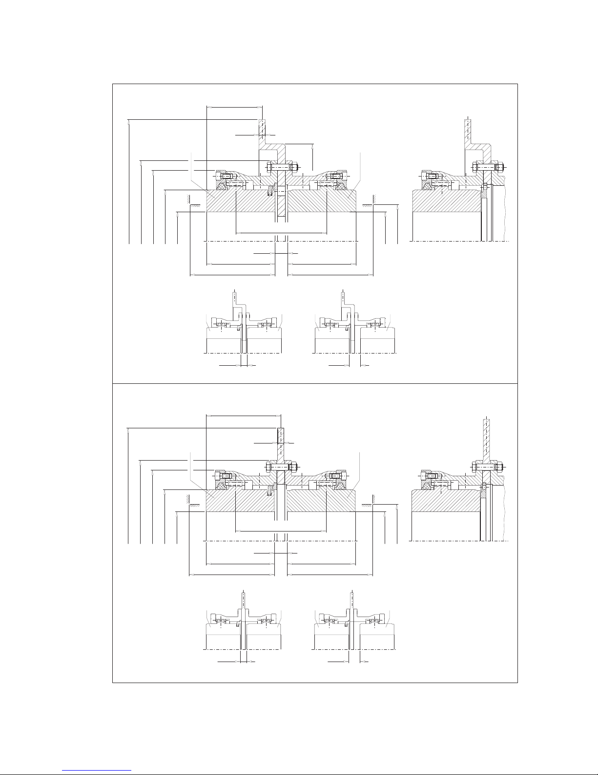
1. Technical data
1.1 Types ZWBT and ZWBG
D1
P
d3
d4
da
P
ll
D2
d6
e1
12.7
S14 S15
121 2
Design A Design AB
d1
S14
VA9
d2
12
D1
P
d3
d4
da
P
ll
D2
d6
e3
12.7
S14 S15
1212
Sizes 112 and 128
Design A Design AB
d1
S14
VA9
12
Sizes 112 and 128
ZWBT
ZWBG

8
ZAPEX 3502 en
Operating instructions 10/2017
Size
Rated
torque Speed Bore
2)
perm.
mis‐
align
ment
Brake disk Weight
TNnmax. D1D2dad3d4d6l P VA9 S14 S15 S14,
S15 d1d2e1e3ZWBT ZWBG
1) from up to up to 3) 3) 4) 4)
Nm 1/min mm mm mm mm mm mm mm mm mm mm mm mm mm mm mm mm mm kg kg
112 1300 3800 0 45 45 143 65 110 45 50 85 69 19 - +0.5 300 181 36.35 64.5 14 14
112 1300
3200
0 45 45 143 65 110 45 50 85 72 22 - +0.5
356 210
26.35 66 17.5 17
128 2500 0 55 55 157 80 128 60 60 105 89 22 29 +0.5 31.35 71 20.5 20
128 2500
2800
0 55 55 157 80 128 60 60 105 86 19 26 +0.5
406 260
28.35 69.5 23.5 22.5
146 4300 0 60 65 177 95 146 75 75 120 101 19 26 +0.5 43.35 84.5 28 27
175 7000 0 70 80 215 112 175 85 90 140 117 21 27 +0.5 59.35 100.5 39 38
146 4300
2500
0 60 65 177 95 146 75 75 120 104 22 29 +0.5
457 311
46.35 86 33 31
175 7000 0 70 80 215 112 175 85 90 140 120 24 30 +0.5 62.35 102 44 42
198 11600 0 85 95 237 135 198 110 100 150 135 24 35 +0.5 72.35 112 55 52
175 7000
2200
0 70 80 215 112 175 85 90 140 120 24 30 +0.5
514 368
62.35 102 49 46
198 11600 0 85 95 237 135 198 110 100 150 135 24 35 +0.5 72.35 112 60 57
230 19000 0 100 110 265 160 230 135 110 160 146 24 36 +0.5 82.35 122 77 72
255 27000 0 115 125 294 185 255 160 125 175 166 26 41 +0.8 98.35 138 98 93
230 19000
1850
0 100 110 265 160 230 135 110 160 146 24 36 +0.5
610 464
82.35 122 88 81
255 27000 0 115 125 294 185 255 160 125 175 166 26 41 +0.8 98.35 138 110 100
290 39000 70 130 145 330 210 290 180 140 200 186 26 46 +0.8 113.35 153 135 125
315 54000 80 145 160 366 230 315 200 160 220 206 26 46 +0.8 133.35 173 165 160
290 39000
1600
70 130 145 330 210 290 180 140 200 189 29 49 +0.8
711 565
116.35 154.5 150 140
315 54000 80 145 160 366 230 315 200 160 220 209 29 49 +0.8 136.35 174.5 180 170
342 69000 90 160 180 392 255 340 225 180 240 241 31 61 +0.8 157.35 195.5 225 205
375 98000 100 180 200 430 290 375 260 200 260 261 31 61 +0.8 177.35 215.5 285 270
415 130000
1400
120 200 220 478 320 415 285 220 300 319 37 99 +0.8
812 660
203.35 238.5 390 355
465 180000 140 225 250 528 360 465 325 240 320 361 41 121 +1.0 225.35 260.5 490 450
Table 1.1: Torques TN, speeds nmax., dimensions and weights
1) The specified torques relate to the teeth and not the shaft-hub connection. This must be checked separately.
2) Max. bore with keyway to DIN 6885/1.
3) Space required for alignment of the coupling parts and replacement of the sealing rings.
4) Weights apply to mean bores.
The rated torques TNapply to:
• daily operating cycle of up to 24 h
• operation within the specified alignment
• operation over the temperature range of between 30 °C and + 80 °C (ambient temperature and/or
temperature of shaft ends).
• up to 25 starts per hour where double the torque is permissible during the start.
For sustained faultfree operation the coupling must be designed with an application
factor appropriate to the application. In the event of a change in operating conditions
(output, speed, changes to the prime mover and driven machine) the design must
always be checked.

9
ZAPEX 3502 en
Operating instructions 10/2017
1.2 Type ZWB
D1
P
d3
d4
da
P
ll
D2
d6
d1
S5S6S7
121212
12
b1
Design A Design AB Design B
S5
VA10
10
ZAPEX 3502 en
Operating instructions 10/2017
Size
Rated
torque Speed Bore2)
perm.
misali
gnment
Brake disk Weight
TNnmax D1/ D2dad3d4d6l P VA10 S5S6S7S5, S6,
S7d1b1
1) from up to 3) 3) 4)
Nm 1/min mm mm mm mm mm mm mm mm mm mm mm mm mm mm mm kg
128 2500 2500 0 55 157 80 128 60 60 105 83 16 23 30 +1 200 75 14
128 2500 2000 0 55 157 80 128 60 60 105 83 16 23 30 +1
250 95
17.5
146 4300 2000 0 65 177 95 146 75 75 120 98 16 23 30 +1 22
146 4300 1600 0 65 177 95 146 75 75 120 100 18 25 32 +1
315 118
29
175 7000 1600 0 80 215 112 175 85 90 140 116 20 26 32 +1 40
198 11600 1600 0 95 237 135 198 110 100 150 131 20 31 42 +1 50
175 7000 1250 0 80 215 112 175 85 90 140 118 22 28 34 +1
400 150
52
198 11600 1250 0 95 237 135 198 110 100 150 133 22 33 44 +1 62
230 19000 1250 0 110 265 160 230 135 110 160 144 22 34 46 +1 78
230 19000 1000 0 110 265 160 230 135 110 160 145 23 35 47 +1
500 190
97
255 27000 1000 0 125 294 185 255 160 125 175 165 25 40 55 +1.5 115
255 27000 1000 0 125 294 185 255 160 125 175 168 28 43 58 +1.5
630 236
155
290 39000 1000 70 145 330 210 290 180 140 200 188 28 48 68 +1.5 180
290 39000 750 70 145 330 210 290 180 140 200 188 28 48 68 +1.5 710 265 210
Table 1.2: Torques TN, speeds nmax., dimensions and weights
1) The specified torques relate to the teeth and not the shaft-hub connection. This must be checked separately.
2) Max. bore with keyway to DIN 6885/1.
3) Space required for alignment of the coupling parts and replacement of the sealing rings.
4) Weights apply to mean bores.
The rated torques TNapply to:
• daily operating cycle of up to 24 h
• operation within the specified alignment
• operation over the temperature range of between 30 °C and + 80 °C (ambient temperature and/or
temperature of shaft ends).
• up to 25 starts per hour where double the torque is permissible during the start.
For sustained faultfree operation the coupling must be designed with an application
factor appropriate to the application. In the event of a change in operating conditions
(output, speed, changes to the prime mover and driven machine) the design must
always be checked.
11
ZAPEX 3502 en
Operating instructions 10/2017
1.3 Types ZWH and ZWHD
D1
P
d3
d4
P
ll
D2
d6
S1
12
12
D1
d3
d4
D2
d6
PP
ll
S1
ZWH
ZWHD
VA11
VA11

12
ZAPEX 3502 en
Operating instructions 10/2017
Size
Rated
torque Speed Bore 2)
perm.
misalign
ment
Weight
TNnmax. D1/ D2d3d4d6l P V A11 S1S1
1) from up to 3) 3) 4)
Nm 1/min mm mm mm mm mm mm mm mm mm mm kg
112 1300 9400 0 45 65 110 45 50 85 28 6 + 1 4.9
128 2500 8300 0 55 80 128 60 60 105 30 6 + 1 7.4
146 4300 7300 0 65 95 146 75 75 120 33 6 + 1 11.5
175 7000 6400 0 80 112 175 85 90 140 46 8 + 1 21
198 11600 5500 0 95 135 198 110 100 150 48 8 + 1 30
230 19000 4700 0 110 160 230 135 110 160 50 8 + 1 45
255 27000 4100 0 125 185 255 160 125 175 55 10 + 1.5 63
290 39000 3700 70 145 210 290 180 140 200 58 10 + 1.5 83
315 54000 3300 80 160 230 315 200 160 220 62 10 + 1.5 110
342 69000 3000 90 180 255 340 225 180 240 70 12 + 1.5 140
375 98000 2700 100 200 290 375 260 200 260 72 12 + 1.5 195
415 130000 2500 120 220 320 415 285 220 300 76 12 + 1.5 255
465 180000 2200 140 250 360 465 325 240 320 90 16 + 2 350
505 250000 2000 160 275 400 505 365 260 340 92 16 + 2 450
545 320000 1800 180 300 440 545 405 280 360 96 16 + 2 570
585 400000 1700 210 330 480 585 445 310 390 102 20 + 2 710
Table 1.3: Torques TN, speeds nmax., dimensions and weights
1) The specified torques relate to the teeth and not the shaft-hub connection. This must be checked separately.
2) Max. bore with keyway to DIN 6885/1.
3) Space required for alignment of the coupling parts and replacement of the sealing rings.
4) Weights apply to mean bores.
The rated torques TNapply to:
• daily operating cycle of up to 24 h
• operation within the specified alignment
• operation over the temperature range of between 30 °C and + 80 °C (ambient temperature and/or
temperature of shaft ends).
• up to 25 starts per hour where double the torque is permissible during the start.
For sustained faultfree operation the coupling must be designed with an application
factor appropriate to the application. In the event of a change in operating conditions
(output, speed, changes to the prime mover and driven machine) the design must
always be checked.

13
ZAPEX 3502 en
Operating instructions 10/2017
2. General notes
2.1 Introduction
These instructions are an integral part of the delivery of the coupling and must be kept in its vicinity for
reference at all times.
All persons involved in the installation, operation, maintenance and repair of the
coupling must have read and understood these operating instructions and must
comply with them at all times. Flender accepts no responsibility for damage or
disruption caused by disregard of these instructions.
The "FLENDER coupling" described in these instructions has been developed for stationary use in
general engineering applications.
The coupling is designed only for the application described in section 1, "Technical data". Other operating
conditions must be contractually agreed.
The coupling must be used and operated strictly in accordance with the conditions laid down in the contract
governing performance and supply agreed by Flender and the customer.
The coupling described in these instructions reflects the state of technical development at the time these
instructions went to print.
In the interest of technical progress we reserve the right to make changes to the individual assemblies and
accessories which we regard as necessary to preserve their essential characteristics and improve their
efficiency and safety.
2.2 Copyright
The copyright to these operating instructions is held by Flender.
These instructions must not be wholly or partly reproduced for competitive purposes, used in any
unauthorised way or made available to third parties without our agreement.
Technical enquiries should be addressed to the following works or to one of our customer services:
Flender GmbH
Schlavenhorst 100
46395 Bocholt
Tel.: +49 (0)2871 / 92-0
Fax: +49 (0)2871 / 92-2596

14
ZAPEX 3502 en
Operating instructions 10/2017
3. Safety instructions
Any changes on the part of the user are not permitted. This applies equally to safety
features designed to prevent accidental contact.
3.1 Obligations of the user
• The operator must ensure that all persons involved in installation, operation, maintenance and repair
have read and understood these operating instructions (BA) and comply with them at all times in order
to:
─ avoid injury or damage,
─ ensure the safety and reliability of the coupling,
─ avoid disruptions and environmental damage through incorrect use.
• During transport, assembly, installation, dismantling, operation and maintenance of the unit, the
relevant safety and environmental regulations must be complied with at all times.
• The coupling may only be operated, maintained and/or repaired by persons qualified for the work
concerned (see "Qualified personnel" on page 3 of this manual).
• All work must be carried out with great care and with due regard to safety.
• All work on the coupling must be carried out only when it is at a standstill.
The drive unit must be secured against being switched on accidentally (e.g. by locking the key switch
or removing the fuses from the power supply). A notice should be attached to the ON switch stating
clearly that work is in progress.
• The coupling must be fitted with suitable safeguards to prevent accidental contact. The operation of the
coupling must not be impaired by the safeguard.
• The drive unit must be shut down as soon as changes to the coupling are detected during operation.
• If the coupling is intended for installation in plant or equipment, the manufacturer of such plant or
equipment must ensure that the contents of the present operating instructions are incorporated in his
own instructions.
• All spare parts must be obtained from Flender.
15
ZAPEX 3502 en
Operating instructions 10/2017
4. Transport and storage
Observe the instructions in section 3, "Safety instructions"!
4.1 Scope of supply
The products supplied are listed in the dispatch papers. Check on receipt to ensure that all the products
listed have actually been delivered. Parts damaged during transport or missing parts must be reported in
writing immediately.
The ZAPEX coupling is delivered in separate parts and/or subassemblies (for transport) ready for
installation, but without oil or grease charge.
4.2 Transport
During transport, use only lifting and handling equipment of sufficient loadbearing
capacity!
The coupling must be transported using suitable transport equipment only.
Different forms of packaging may be used depending on the size of the coupling and method of transport.
Unless otherwise agreed, the packaging complies with the HPE Packaging Guidelines.
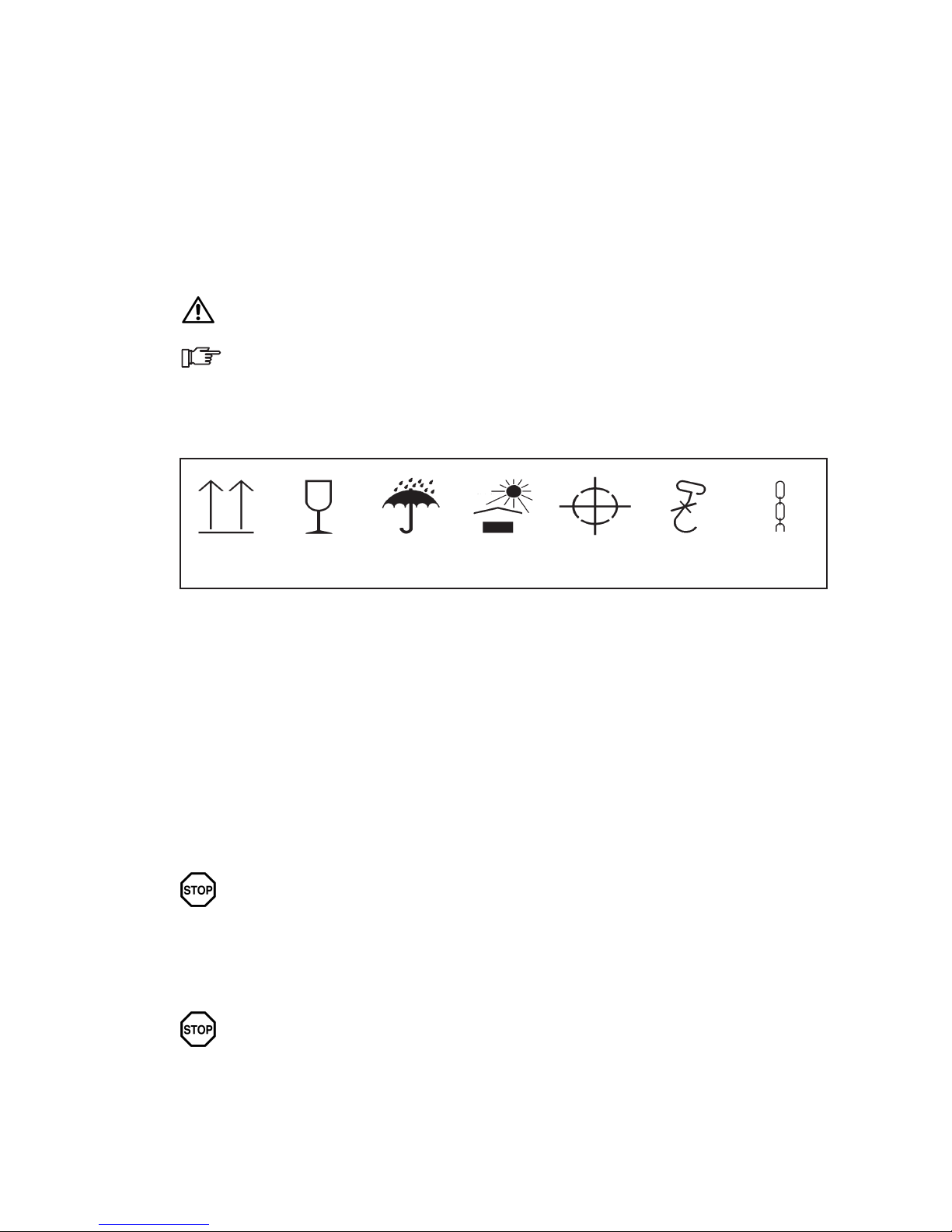
The symbols marked on the packing must be observed at all times. These have the following meanings:
Top Fragile Keep dry Keep cool Centre of
gravity
Use no hand
hook
Attach
here
Fig. 1: Transport symbols
4.3 Storage of the coupling
4.3.1 Storage of the coupling parts
The coupling is delivered in a preserved condition and can be stored in a covered, dry place for up to
6 months. If the unit is to be stored for a longer period, it should be treated with a longterm preservative
agent (Flender must be consulted).
4.3.2 Storage of the DUO sealing rings
4.3.2.1 General
Correct storage will preserve the service life of the DUO sealing rings (12). Unfavourable storage
conditions and improper treatment will negatively affect the physical properties of the DUO sealing
rings (12). Such negative effects may be caused by e.g. the action of ozone, extreme temperatures, light,
moisture, or solvents.
The DUO sealing rings (12) must not be stored while still fastened on the coupling
part (1, 2).
4.3.2.2 Storage area
The storage area must be dry and free from dust. The DUO sealing rings (12) must not be stored with
chemicals, solvents, motor fuels, acids, etc. Furthermore, they should be protected against light, in
particular direct sunlight and bright artificial light with a high ultraviolet content.
The storage areas must not contain any ozonegenerating equipment, e.g. fluorescent
light sources, mercury vapour lamps, highvoltage electrical equipment. Damp
storage areas are unsuitable. Ensure that no condensation occurs. The most
favourable atmospheric humidity is below 65 %.

16
ZAPEX 3502 en
Operating instructions 10/2017
5. Technical description
Observe the instructions in section 3, "Safety instructions"!
If a dimensioned drawing has been made out for the coupling, the data in this drawing
must be given priority.
5.1 General description
ZAPEX type ZWBT, ZWBG, ZWB, ZWH and ZWHD couplings are provided for connecting two shafts. The
shaft ends to be connected must be supported immediately upstream of and downstream of the coupling.
ZAPEX couplings are suitable for clockwise and anticlockwise rotation and reversing operation.
The coupling parts (1, 2) with external teeth engage with the internal teeth of the flanged sleeves (5) and/or
coupling sleeve (5).
For the types ZWBT, ZWB, ZWBG and ZWH, DUO sealing rings (12) are used on the outside for sealing
the oil chambers.
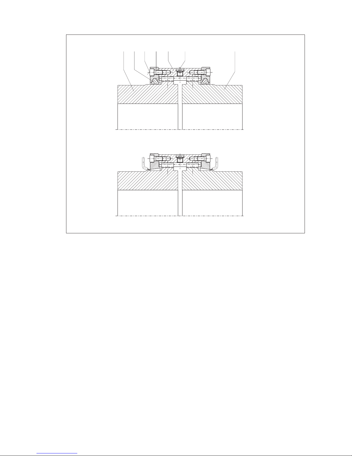
5.1.1 Types ZWBT, ZWBG, ZWB
1121110 5 8 9 6 2
ZWBG
52
13
ZWBT
ZWB
(7)
Torque transmission is effected from the shaft over parallel key, shrink fit or a comparable connection to
the coupling part (1), then over the tooth system to the sleeve (5) and then via the fitting-screw
connection (8, 9) to the second sleeve (5), over the tooth system to the coupling part (2) and then again
via the parallel key, shrink fit or a comparable connection to the shaft. The brake disk (13) is located
between the flanged sleeves (5).
In case of types ZWBT and ZWBG the axial backlash is restricted by the twopart retaining ring (52).
17
ZAPEX 3502 en
Operating instructions 10/2017
5.1.2 Types ZWH and ZWHD
1121110 5 6 2
ZWH
ZWHD
(7)
Torque is transmitted from the shaft over parallel key, shrink fit or a comparable connection to the coupling
part (1), then over the tooth system to the coupling sleeve (5) and from here over the tooth system to the
coupling part (2) and then again via the parallel key, shrink fit or a comparable connection to the shaft.
Type ZWHD is designed for flow-through lubrication and is thus not equipped with DUO sealing rings (12).

18
ZAPEX 3502 en
Operating instructions 10/2017
6. Fitting
Observe the instructions in section 3, "Safety instructions"!
If a dimensioned drawing has been made out for the coupling, the data in this drawing
must be given priority.
6.1 Instructions for applying the finished bore and fitting the axial retaining means, set screws and balancing
According to the order placed, the coupling parts (1/2) for removal by oil-hydraulic shrinking off are
delivered with finished bores.
6.1.1 Finished bore for parallel-key connection
• Depreserve coupling parts (1/2).
Note manufacturer’s instructions for handling solvent.
For making the finished bore, the coupling parts must be clamped as shown in the following figure.
The clamping chuck must always be opposite the sealing surface.
The coupling part must be aligned carefully. For the permissible radial eccentricity see DIN ISO 286 degree
of fundamental tolerance IT 6 (see table 6.1).
The maximum permissible bore diameters (see section 1) are designed for
parallel-key connections without taper action to DIN 6885/1 and must not under any
circumstances be exceeded.
When the keyway is to be designed deviating from DIN 6885/1 for a parallel-key
connection, Flender should be consulted.
If other shaft-hub connections (e.g. spline bore hub profile, tapered or stepped bores, parallel-key
connections with tightening) are to be used instead of the provided parallel-key connection, Flender
should be consulted.
Failure to observe these instructions may result in breakage of the coupling.
Danger from flying fragments!

19
ZAPEX 3502 en
Operating instructions 10/2017
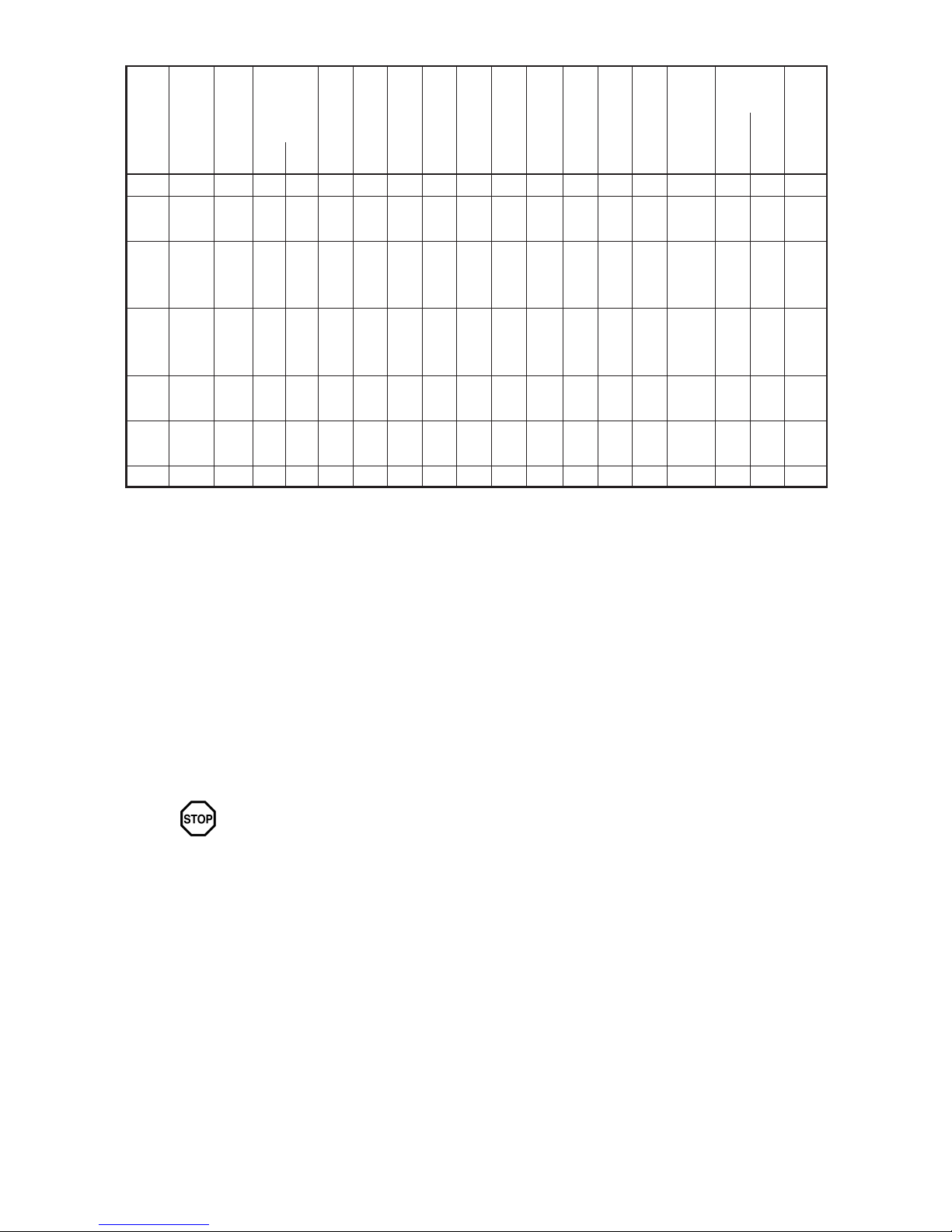
Diameter or nominal
dimension range
> 18
up to
30
> 30
up to
50
> 50
up to
80
> 80
up to
120
> 120
up to
180
> 180
up to
250
> 250
up to
315
> 315
up to
330
Perm. deviation
according
to DIN ISO 286/1, IT6
0.013 0.016 0.019 0.022 0.025 0.029 0.032 0.036
Table 6.1: Permissible radial runout
A
A
IT 6
D
3.2
ChuckSealing surface
In case of a parallel-key connection the following is recommended for bore and shaft:
Shaft end tolerances h6 k6 m6 n6 p6 s6
Bore tolerances P7 M7 K7 J7 H7 F7
Table 6.2: Fit pairs
The tolerance field must be observed in order to restrict the hub tension resulting from
the oversize to the permissible load. Failure to adhere to the assigned tolerance zones
may impair the shafthub connection.
Failure to observe these instructions may result in breakage of the coupling.
Danger from flying fragments!
6.1.1.1 Parallel keyway
With the parallel key connection to DIN 6885/1 and a single keyway the tolerance zone of the hub keyway
width ISO P9 is recommended.
With the parallel key connection to DIN 6885/1 and two keyways the tolerance zone of the hub keyway
width ISO JS9 is recommended.
6.1.2 Axial securing in case of parallel-key connection
A set screw or end plate must be provided to secure the coupling parts axially. If end plates are used,
Flender must be consulted with regard to machining the recesses in the coupling parts.
20
ZAPEX 3502 en
Operating instructions 10/2017
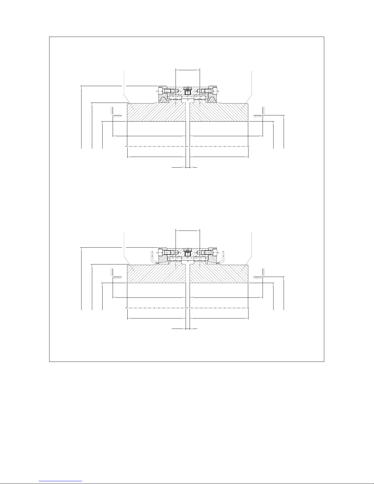
6.1.3 Set screws in case of parallel-key connection
Hexagon socket set screws with cup points to DIN 916 must be used for set screws.
The following guidelines must be observed!
The length of the set screw must be selected so that it fills the threaded hole, but does
not project from the hub (Lmin. = d1).
The set screws should generally be arranged on the parallel key. Check the length of
the parallel key.
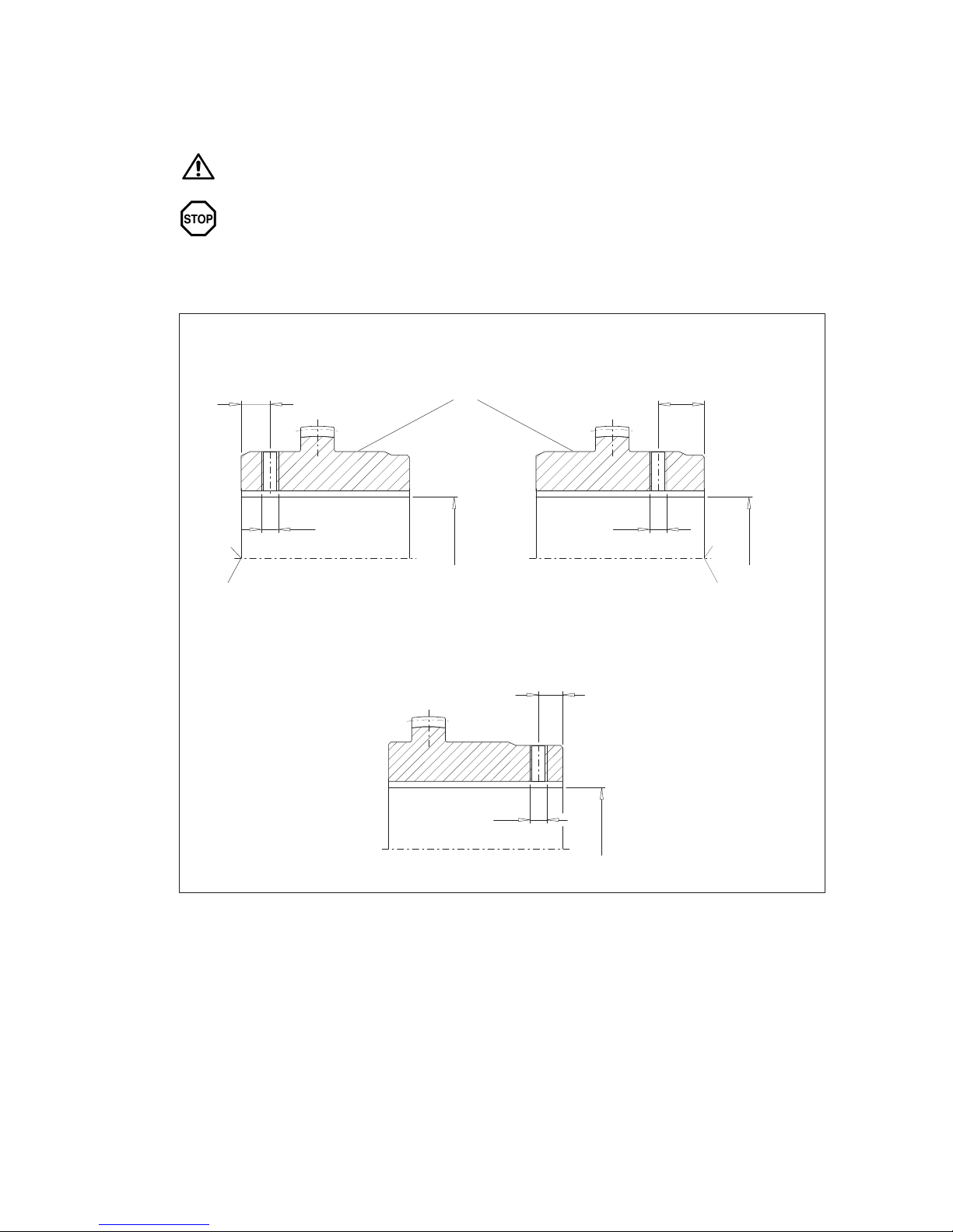
The threaded holes are to be arranged in accordance with the drawing considering the used version A or
B for the coupling parts (1/2).
In case of size 112, the set screws must generally be arranged in the hub side which has not been ground.
Sealing surface
Design A
e1
d1
D
Design B
e2
d1
d1
D
Part 1/2 for ZWH only
B-side
Part 1/2
e4
D
A-side
This manual suits for next models
4
Table of contents


