Fletcher-Terry Fletcher Saber 250-A User manual

Owner’s Manual
Fletcher Saber™ 250-A
For Accurate and Efficient Saw Tooth Hanger Installation
Form 032404
The Fletcher
-
Terry Company
65 Spring Lane • Farmington, CT USA 06032-3311
Tel 860.677.7331 or 800.843.3826 • Fax 860.676.8858 • www.fletcher-terry.com

First, we’d like to
congratulate you for adding
the Saber 250-A to your
production line. From now on
your operators will be able to
insert saw tooth hangers with
efficiency, accuracy, and
reliability. It’s easy to use and
designed to require minimal
maintenance. Regardless of
the size of the frame or
thickness of the moulding, the
Saber 250-A will secure a 5-
tooth hanger perfectly placed
and instantly secure.
Next, we ask you to inspect
the two containers that were
used to ship the Saber 250-A.
If damaged, please contact
your carrier and file a claim.
Locate the warranty card that
was shipped with this manual
and return it to The Fletcher-
Terry Company to activate
the warranty.
Now, you’re ready to set up
and operate the Saber 250-A.
Page 2
Page 3
Page 7
Page 12
Page 14
Page 16
Product Warranty
The Fletcher-Terry Company warrants the machine purchased to be free from defects in parts and workmanship for (2) two years from the date of
purchase. The Fletcher-Terry Company warrants that it will repair or replace any such defective machine or replace parts, providing the machine
has been under normal use and service and the defective part or machine is returned to The Fletcher-Terry Company at the purchaser’s expense.
The Fletcher-Terry Company must authorize the return in writing. Proof of purchase must be submitted to validate warranty coverage.
The warranty is in lieu of all other agreements and warranties expressed or implied. THE FLETCHER-TERRY COMPANY DOES HEREBY
EXPRESSLY DISCLAIM ANY WARRANTIES OF MERCHANTABILITY OR FITNESS FOR A PARTICULAR PURPOSE. The Fletcher-Terry
Company does not authorize any company employee or representative to assume for it any other liability than that set forth in this Product
Warranty. The Fletcher-Terry Company shall not be liable for any damages or losses, whether incidental or consequential or direct or indirect,
arising out of the use or abuse of this machine. In any event, THE PURCHASER’S SOLE AND EXCLUSIVE REMEDY UNDER THIS OR ANY
OTHER WARRANTY IS LIMITED TO RETU
RN OF THE PURCHASE PRICE PAID FOR THIS MACHINE.

Please read through this manual before operating the Saber™ 250-A. If
after reviewing these pages you still have questions about using the
machine, contact our Customer Service Department: (toll-free)
1.800.843.3826 in the U.S.; outside the U.S. call 860-677-7331;
ÿIt is the employer’s responsibility to enforce compliance with these safety warnings and
procedures by allwho use the Saber 250-A. Keep this manual available so all employees
have access toit and the opportunity to review procedures periodically.
ÿThe intended purpose of the Saber 250-A is to insert saw tooth hangers inpicture frames
of various shapes, sizes, andmaterials. Itmust not be modified or used for any other
application or purpose.
ÿUse safety glasses. The operatorof this machine, and others in the work area,must wear
safety glasses with rigidside shields. Wear ear protection. Ear protection is recommended
in any work environment where repetitive, mechanical machinery is in operation.
ÿOnly connect the Saber 250-Ato an air supply with a coupling that removes all pressure
when disconnected. Always disconnect the machine from the air supply beforeperforming
maintenance, removing a jamor cleaning the Saber 250-A.Even if a hangerstrip is not
visible on the guide, assume that there may be oneor two hangers remainingin the
machine.
ÿUse clean, dry, regulated compressed air at a minimum pressure of 100 PSI at 2 CFM.
The system includes a filter and pressure regulator. Do not connect this machine to an air
supply withmaximum potential pressure greater than 150 PSI.
ÿNever use oxygen, carbon dioxide, combustible gases or any type of bottled gas as a
source for this machine. Explosion and serious injury may result.
ÿNever use the machine if the air supply is compromised, themachine is missing parts, or
repair of the Saber250-A is required. Do not use the machine if the safety warning labels
are missing or unreadable. Donot use the machine ifthe ram safety guard ismissing or
broken. Contact a Fletcher-Terry Customer Service Representative for replacement labels
or parts.
ÿOnly use the parts, supplies,and accessories that are recommendedby Fletcher-Terry.
ÿUse care when loading the hanger strips onto the hangerguide, making sure that you do
not inadvertentlyactivate the T-bar switch.
ÿDo not over-reach or use the Saber 250-A from an awkward or insecure position. Make
sure that the workarea is well lit, freefrom clutter, and set upin a way that promotes
proper ergonomics.
ÿþýü ú

The Saber 250-A has been
shipped to you in two
containers. The longer,
flatter carton contains the
Base (Figure 1).
The other box contains the
Tower Assembly (Figure
2), the Fence (Figure 3),
and a Parts Bag.
You will have found that the
Parts Bag contained:
a) This Owners’ Manual
b) A Warranty Card
c) Flat Head Socket Cap
Screws (2)
d) Hex Key (1)
e) Triangle Template
[for squaring] (1)
All instructions in this manual assume that
you are facing the front of the machine and
that the machine has been placed on
a flat and secure surface.
If anything is missing, please contact a Fletcher-Terry Customer Service Representative at
800.843.3826, at 860.677.7331, or customerservice@fletcher-terry.com.
ÿþýü ú
Figure 3 FENCE
VIEW A: FROM RIGHT SIDE
VIEW B: FROM THE FRONT
VIEW C: FROM ABOVE
Figure 4
Figure 5
Figure 6
ÿþýü ú
Before assembling the machine,
determine whether you will
anchor the Saber 250-A to your
work surface. Placing and
securing the machine will be a
matter of personal preference
and it is left to the owner to
decide how best to use the
Saber.
The Saber 250-A should be
placed so that the front of the
machine is facing the operator.
Be sure to leave sufficient room
for attaching the base
assembly. The base assembly
will run along the front edge of
the workstation.
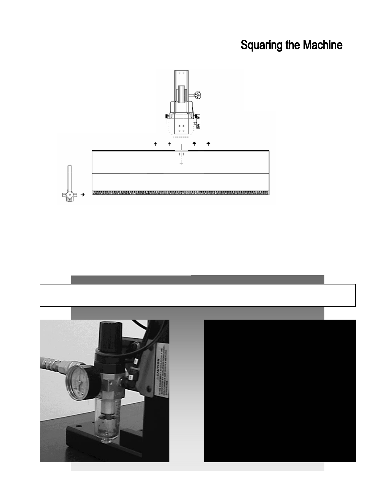
If you decide to anchor the
Saber 250-A to your work
surface, locate the four,
predrilled holes on the
crossmember of the frame
(
Figure 7).
These will allow you
to secure the machine with four
bolts (not included).
Please Note:
When the base is attached
to the tower, a squaring
procedure must be
followed to ensure proper
alignment.
(See Figure 8.)
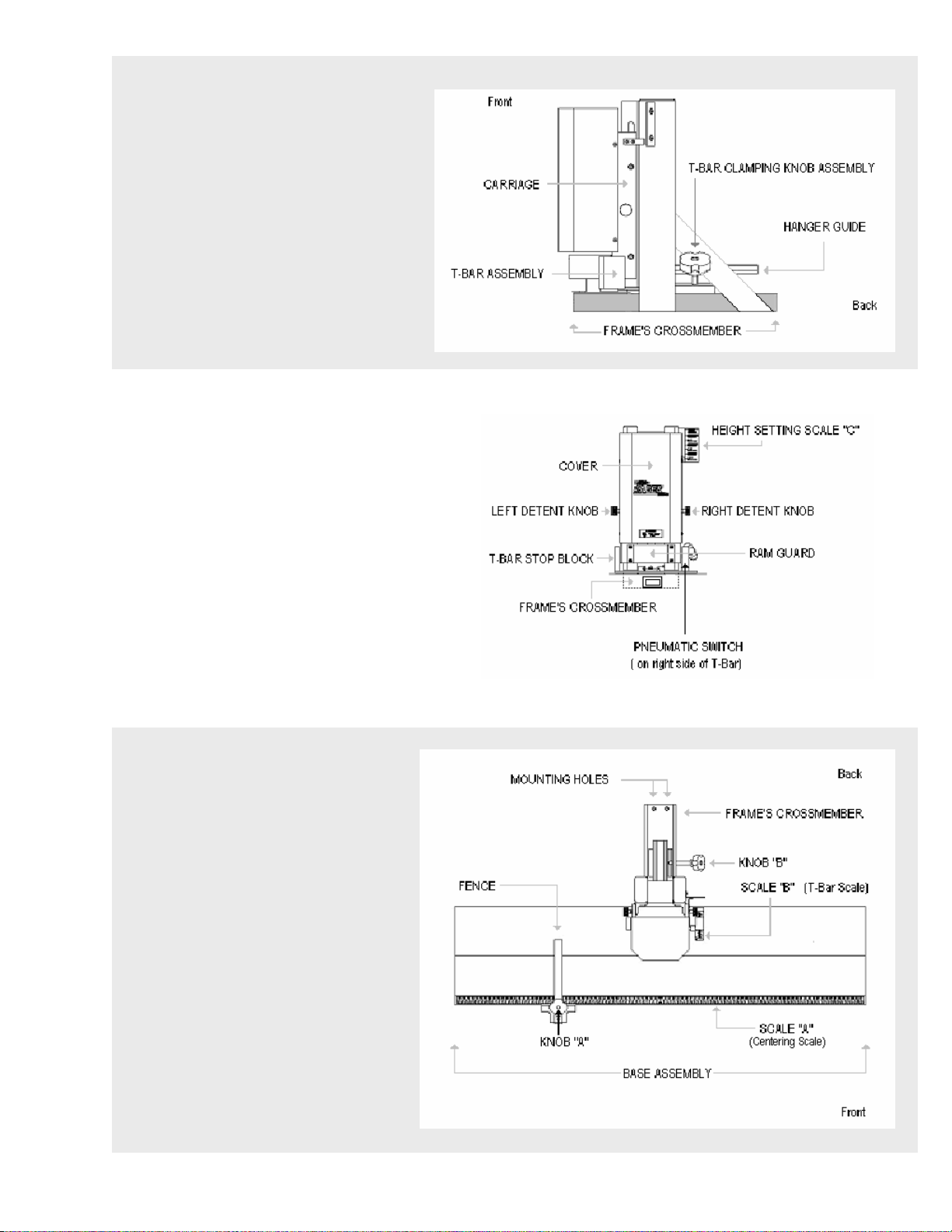
Figure 7 (Shown with machine’s cover removed)
þýüû ú
With the machine properly placed (and
optionally mounted to the worksurface),
raise the carriage to its uppermost position
on the tower. Pull out the detent knobs to
release the carriage and guide it upwards
until it locksin place when it reaches the
appropriate location.
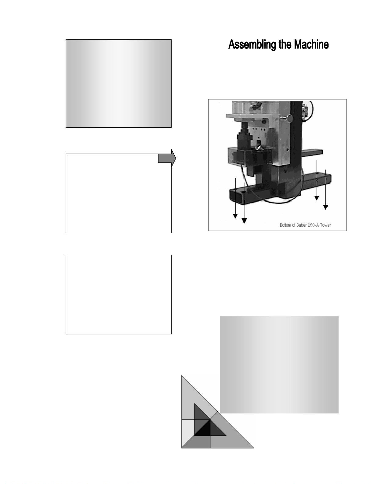
Set the T
-
bar to a 2
-
inch depth setting. Do
this by loosening the T-bar clamping knob
and moving the entire T-bar assembly until a
2-inch setting is reflected on the T-bar scale.
Tighten the knob.
Place the enclosed
triangle template
squarely against the
fence and across the T-
bar assembly. Use a
piece of material or
matting (approximately
1/8” thick) as a platform
under the template to
ensure that thetriangle
will bump up against the
fence and the T-bar
assembly.
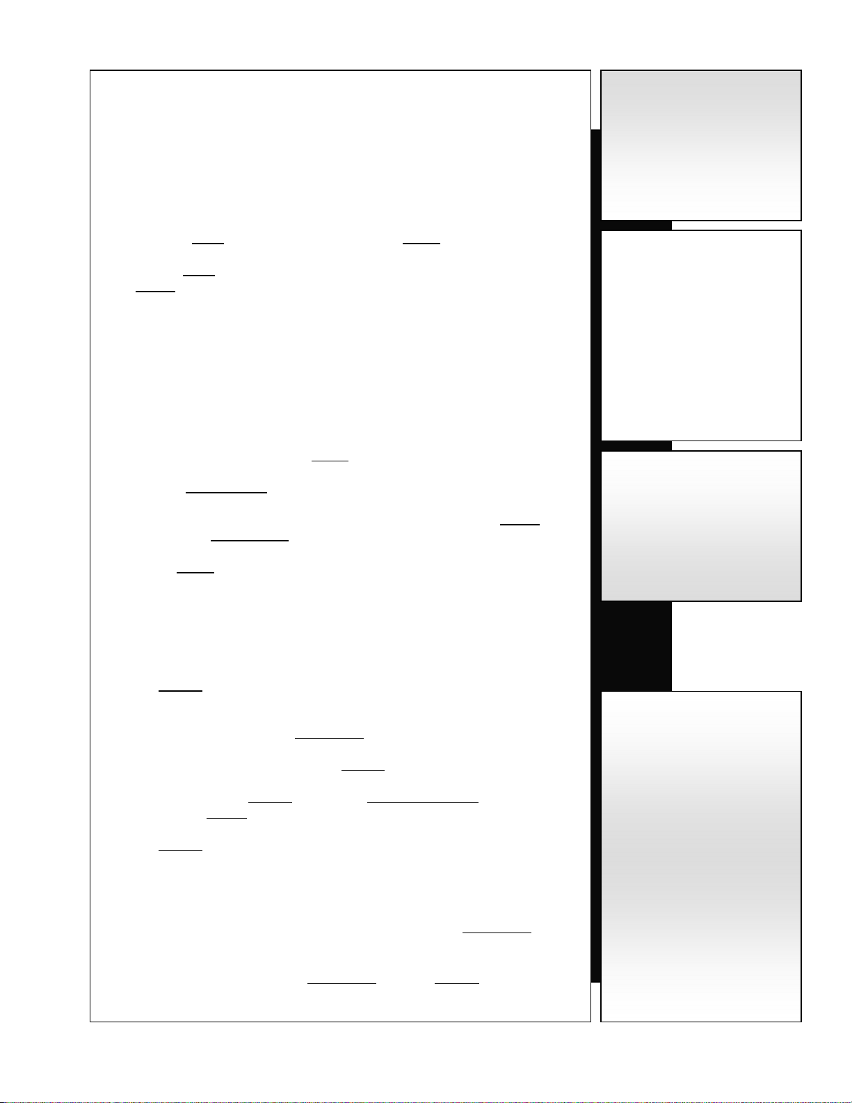
Attach the base to the tower assembly by placing it atop
the machine’s crossmember. Align the screw holes and
insert screws. Loosely tighten the left, but do not tighten
the right screw. The right screw will not be tightened until
the squaring procedure is complete. Attach the fence
assembly and position it at the 10” mark on Scale A.
Gentl
y move the base assembly until the
triangle is perfectly squared tothe fence and
T-bar. When you have done so, tighten the
right screw and then the left.
THE MACHINE IS NOW PROPERLY SQUARED AND YOU MAY ATTACH YOUR SOURCE OF COMPRESSED AIR TO
THE FILTER / REGULATOR AT THE LEFT REAR OF THE SABER 250-A
Establishing a Proper Air Supply:
Attach your compressed air hose to the machine
using clean, dry air (minimum 100 PSI with the
regulator set at 75 PSI).
You may choose to adjust pressure depending
on the size and material of the frame. This may
be especially important if using the small frame
adapter. (See “Optional Equipment”)
Certain safety precautions are required when
using pneumatic tools in order to prevent injury
to the user and others in the area. Read and
follow all instructions and safety warnings in
this manual.
ÿþýü ú
Figure 9
Figure 8

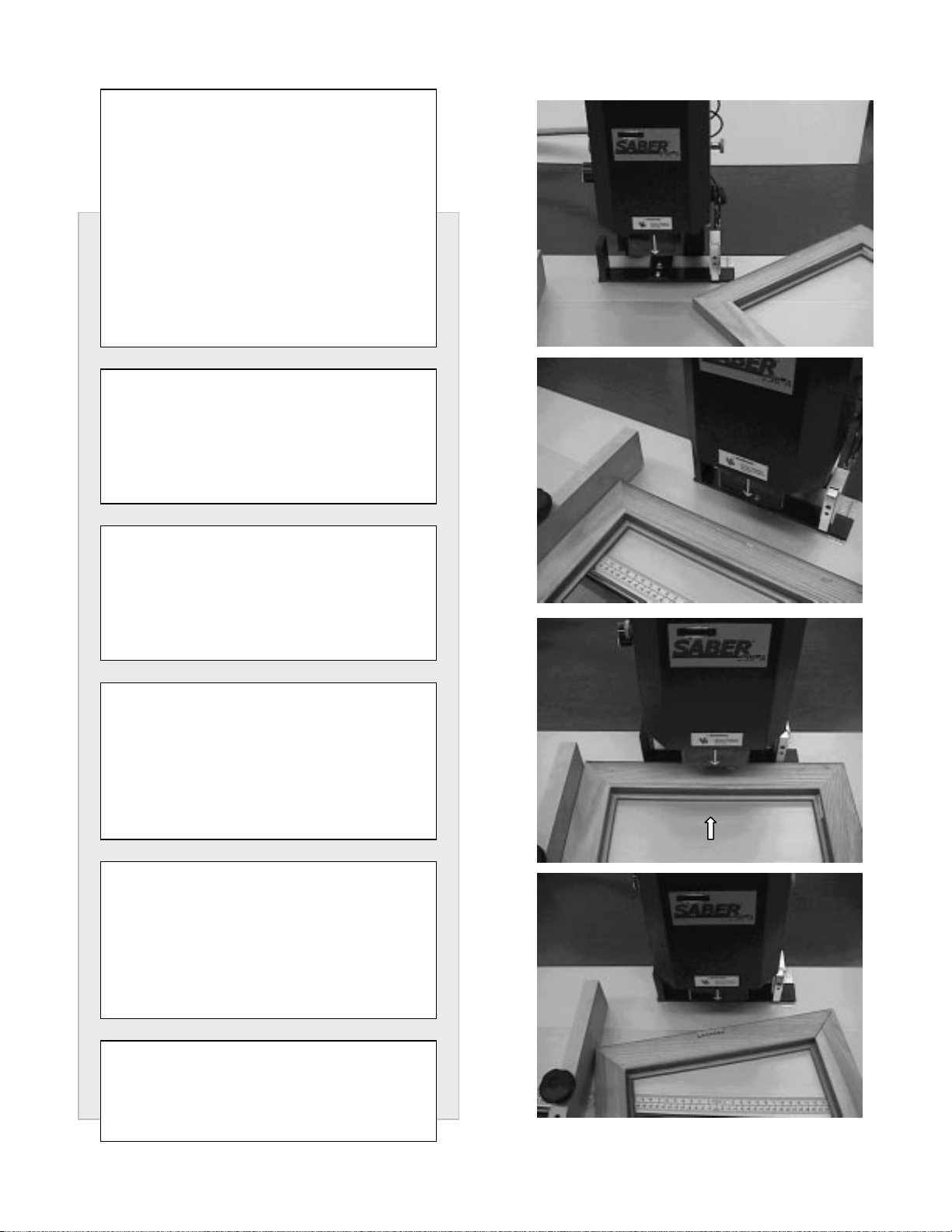
A. Load the Hanger Strip
B. Measure the Frame and Adjust the Machine
C. Activate the Saber 250-A
Saw tooth hanger strips
contain 25 collated hangers.
Individual hangers are
barbed to ensure maximum
hold when inserted into a
frame.
The hanger strip is loaded
onto the guide, barbs
pointing downwards and
teeth facing the machine’s
operator, i.e., the front of the
Saber 250-A.
Once the strip is loaded onto
the guide, the operator
pushes the strip forward
toward the front of the
machine until the hanger
strip stops.
The required hanger strips (part
number 08-810) may be ordered
by contacting the Fletcher-Terry
Customer Service Department at
800.843-3826; outside the U.S.,
call 860.677.7331; or
customerservi[email protected]
ÿþ üûúù ø÷ö õúôóöò ñøòðï
Figure 10 (Top View)
úóö

Coming Up:
Page 9: A quick review and instructions for taking measurements andadjusting the Saber 250-A.
Page 10: Some examples, product notes and safety tips.
Page 11: How to drive a sawtooth hanger using the Saber 250-A.
ÿþ üûúùø÷û öõû ô÷úóû úòñ ðñïøùö öõû üúîõíòû
The Saber 250-A requires
the operator to determine
three measurements before
proper placement of a saw
tooth hanger can be made:
a. The width of the
frame;
b. The hanger’s
placement from
the top of the
frame to the
centerline of the
hanger;
c. The height or
thickness of the
frame.
Figure 11
úû
Taking measurements and adjusting the Saber 250-A:
ÿA. How wide are the frames you will be processing?
i. Measure the width from outside the left edge to outside the right edge of the frame.
(measurement “a” in Figure 11)
ii. Locate the Fence assembly and loosen it by twisting Knob A, counterclockwise.
iii. Slide the Fence until its edge is aligned with the mark on the Centering Scale,
Scale A, that corresponds to the frame’s width.
iv. Tighten Knob A.
ÿB. Where do you want the hanger to be inserted, relative to the top
edge of the frame?
i. Measure or approximate the distance between the top edge of the frame and the point
at which you wish to insert the hanger. (measurement “b” in Figure 11)
ii. Loosen the T-Bar Clamping Knob, Knob B, by turning it counterclockwise.
iii. Move the T-Bar Assembly by gently pushing or pulling the unit along its track.
iv. Align the T-Bar so that measurement “b” is reflected on the T-Bar scale, Scale B,
located on the Base Assembly.
v. Tighten Knob B.
ÿC. How high is the frame at its greatest thickness?
i. With the frame laying flat on a surface, determine its height at its thickest cross-section.
(measurement “c” in Figure 11)
ii. The Carriage of the Saber 250-A is spring-loaded and slides up and down the tower of
the machine.
iii. Firmly pull out the left and right Detent Knobs at the same time.
iv. You will notice that doing so will free the Carriagetoglideupordownasyouwish.
v. This movement of the Carriage will cause the Height Setting Pointer to move along the
Height Scale, Scale C, at the upper right hand corner of the machine.
vi. The Carriage will lock into any one of six (6) pre-set positions that correspond to a
range of heights.
vii. Find the range that includes measurement “c.”
viii. Feel for the locking location at that range by gently releasing the Detent Knobs at or
near the correct setting.
ix. Fully release any pressure on the Detent Knobs to lock the Carriage in place at the
appropriate height setting.
Example “a”
A frame measures 10 inches
across. After loosening the fence
with Knob A, move the fence so
that the Centering Scale (Scale A)
reads 10 inches. Tighten the knob
tolockthefenceinplace.
Example “b”
After assessing where a hanger
should be placed on a certain
frame, the operator measures the
distance from the top edge of the
frame to that spot and finds it to be
two inches (2”). The operator then
moves the T-bar assembly to 2"
on Scale B and then locks the T-
bar assembly in place by turning
knob B.
Example “c”
A frame measures 2.3” high at its
greatest thickness. Using the
Detent Knobs, the operator locks
the carriage into place at the 1.5”
to 2.5” setting as marked on the
Height Settings Scale (Scale C).
Please Note:
The Height Scale
(Scale C) shows six (6)
different height ranges.
Choose the one that will
accommodate
measurement “c.”
2.5” to 3.5”
2.0” to 3.0”
1.5” to 2.5”
1.0” to 2.0”
0.5” to 1.5”
0.5” to 1.0”
ÿþýü ú
Safety Tips:
It is recommended that the
hanger be driven at the thickest
portion of the frame. The further
it is driven from a thick portion,
the more likely it becomes that
the frame will kick upward when
the hanger is inserted.
Set the carriage so that there is
a minimum clearance of 0.25"
from frame to the bottom of the
ram guard. Keep in mind that
the machine will operate
properly with greater
clearances, but there is less
room for errors or injury when
this space is kept to a minimum.
Please Note:
While this manual uses non-
metric measurements in all of
its examples, the Saber 250-A
has both imperial and metric
scales.
Let’s Review:
ÿYou have read and
understand the safety
instructions listed
inside the front cover of
this manual.
ÿYou are familiar with
the operating
procedures and safety
guidelines of your
employer.
ÿYou are wearing safety
glasses prior to working
with this equipment.
ÿYou have assembled
the Saber 250-A and
have created an
uncluttered work area
for the machine.
ÿIt is securely positioned
(possibly mounted) on
your work surface.
ÿYou are familiar with
the major components
of the Saber 250-A and
know that three
measurements must be
taken before adjusting
the machine to yourrun
specifications.
ÿThe machine has been
connected to your
source of clean, dry,
compressed air,
accordingtothe
specifications listed on
the bottom of page 6,
and in compliance with
your company’s
operating procedures.
The Saber 250-A has been
designed to deliver precise
installation of saw tooth hangers
with great reliability. If, for any
reason, a hanger jams, the
machine will not fire.
Uneven pressure on the T-Bar
will automatically interrupt the
operation of the ram. The
slightest release of pressure will
do the same. This design
feature prevents injury and
unintended firing.
ÿþýü úù
Once all three measurements
(a, b, and c) have been taken
and the machine has been
readied with these measures
being reflected on Scales A, B,
and C, the operator is now
ready to insert the saw tooth
hanger.
ÿþ
The frame is inserted backside-
up with its left edge pressed
against the left fence.
þ
The top edge of the frame is
leveled against the T-Bar
assembly.
þ
The operator then pushes the
frame squarely into the machine
(against the T-Bar), thereby
triggering the pneumatic switch.
þ
When the pneumatic cylinder is
activated, the machine’s ram
will insert the hanger into the
frame at the proper location.
This process can be repeated
25 times per hanger strip.
þ
ÿÿ

The Saber 250-A can be outfitted with one or more of the following optional devices:
A. Small Frame Adapter
(Part # 04-553)
:For frames that are too small to be processed
using the standard T-Bar assembly and pneumatic switch.
B. Foot Pedal
(Part # 04-552)
:To give the machine operator an alternative method for
activating the Saber 250-A.
C. Additional Fence Assembly
(Part # 04-551)
:The Saber 250-A comes equipped with
a universal fence assembly that is used for squaring the left edge of a picture frame. It
may also be used to square the right edge of a picture frame that requires two side-by-
side saw tooth hangers. When two hangers must be inserted into the top piece of a
picture frame, a second fence assembly may be ordered (to attach on the right side of
the base) in order to provide the operator with a step-saving method of installing the
hangers.
Using a Small Frame
Adapter to Insert
Hangers
The sizes of some frames
are such that they will be too
small to be effectively
handledby the standard T-
Bar assembly of the Saber
250-A. Therefore, The
Fletcher-Terry Company has
designed an optional adapter
that will accommodate such
frames.
The adapteris fittedon the
T-Bar stop block on the T-
Bar assembly. The adapter’s
bracket is securely tightened
to the Saberby turning Knob
D. Do not over-tighten. The
procedure for inserting the
hanger is unchanged.
Note: Add ¼” to measurement
“b” to compensate for the
thickness of the Actuator Bar
when setting the T-bar Scale.
That is, if you wish to place the
hanger ¼” from the top edge of
the frame, add ¼” and set Scale
Bto½”.
ÿþ üûúùù ø÷úûö ÿõú
ô
óö
÷
úö

Inserting Two Hangers Per Frame Using a Second Fence.
ÿThe fence designed for the Saber-250-A may be attached to the base on either the left or the right side of the
machine. When inserting a single hanger, the fenceis positioned to the left. If aframe’s size necessitates a
two-hanger configuration, a second fence assembly may be used to streamline the process.
ÿThe secondfence is the identical twin to the standard fence. They can be used interchangeably. They are
attachedto the base the same way and are positionedso that there is a fence to the leftof “zero”on the
centering scale, and there is oneto the right of thismark.
The procedure for inserting two hangers usingthe second fenceis similar to the procedure for insertingone:
ÿMeasurements are taken and the machine isadjusted toreflect them. Whereasa single hanger is centered on
a frame,two hangers must be lined up horizontally at an equal distance fromthe center (or at an equal
distance from the frame’s edge).
ÿThe operator manually determines the placement of thefirst hanger and takes thatmeasurement. The
essential thing to remember is that the placement and measurement of the second hanger must mirror that of
the first.Both fences must be positioned so that theircorresponding edges areset to the same mark on either
side of “zero.” (See Figure 13 above.)
ÿThe installation processis completed by firstinserting the right hanger. (Square the frame to the left fence
before pressing it against the pneumatic switch to activate thehanger.) Repeat this process for the left hanger
by squaring the frame against the right fence.
Using an Optional Foot
Pedal.
Use of thefoot pedal is a matter of
the personal preference of the
machine operator. It is assembled
according to the instructions enclosed
with the item.
Figure 13
ÿþ üûûú ùø÷öõ
þ ÷÷úûöõ üøø øõ
ùöø
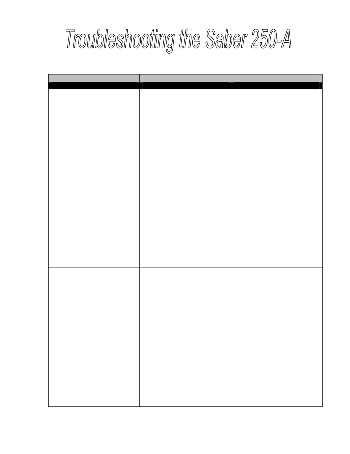
Problem or Issue Possible Reason Action
The machine fires prematurely. The top edge of the frame is
pressing against the activation
switch before the side edge is
squared on the fence.
Alwayspositionthesideedgeof
the frame before pushing the top
edge against the T-Bar (i.e., the
pneumatic switch).
A hanger is jammed in the
machine. In the unlikely event of a jam, one
of two things may have
happened. The hanger strip has
been placed on the magazine
incorrectly, or the hanger strip
was bent or damaged during
shipping or handling.
The operator must manually
remove the jam by first
disconnecting the air supply, then
freeing the remaining hanger
strip from the rear of the
machine, and finally ejecting the
jammed hanger. Only one hanger
can ever be jammed because of
the machine’s design.
To remove the hanger strip,
locate the ram guard above the
T-bar assembly and push up on
the orange release lever.
Remove the hanger and then
make sure the hanger strip is
reloaded properly before
reconnecting the air supply. (See
page 6.)
There is no air pressure. The source of compressed air is
disconnected or improperly
connected to the Saber 250-A.
Re-check your air source and
hose connections to make sure
that you have correctly attached
the Saber 250-A to your existing
air supply system.
If the pneumatic drive still does
not work properly, contact your
Fletcher-Terry Customer Service
Representative for further advice.
There is insufficient air pressure. Pressure settings are not
properly set.
The machine is being used on
material, or in a way for which it
is not designed.
Check your company’s
compressed air source to make
sure that it is in proper working
order. Verify that all settings are
consistent with the
recommendations listed on page
6 of this manual.
ÿþýü úù

Hanger is not fully installed. (a) There is too much clearance
between the picture frame and
the ram tip at its extended
position.
(b) There is not enough air
pressure.
(a) Using the detent knobs on
either side of the drive carriage,
lower the height setting to an
appropriate range. A ¼”
clearance is sufficient.
(b) Increase air pressure until the
hanger is fully installed.
Hanger is not centered (left-
right). The fence is not positioned
properly. Refer to page 9 in order to review
measurement settings.
Hanger is not centered (up-
down). The hanger need not be centered
vertically on the top edge of the
frame. However, if the hanger is
not placed where the operator
wants it, there is likely a problem
with the measurements reflected
on the scale on Scale B.
Refer to page 9 in order to review
measurement settings.
Hanger strip does not feed
properly. (a) The hanger strip may be
slightly bent or twisted.
(b) The flow control valve is
closed or clogged.
(a) The hanger strip can be fed
with minimal misshape, however,
it should be manually corrected if
possible. If the strip is badly bent,
the strip needs to be replaced.
(b) Adjust the flow control valve
to let more air into the indexing
cylinder.
Frame will not release. There may have been less than
¼” clearance between the ram tip
and the picture frame.
Using the detent knobs on both
sides of the carriage, raise the
ram to an appropriate height
setting range. A ¼” clearance is
necessary to avoid trapping the
frame.
For assistance, contact The Fletcher-Terry Company Customer Service Department at
800.843.3826, 860.677.7331, or customerservice@fletcher-terry.com.
ÿþýü úù
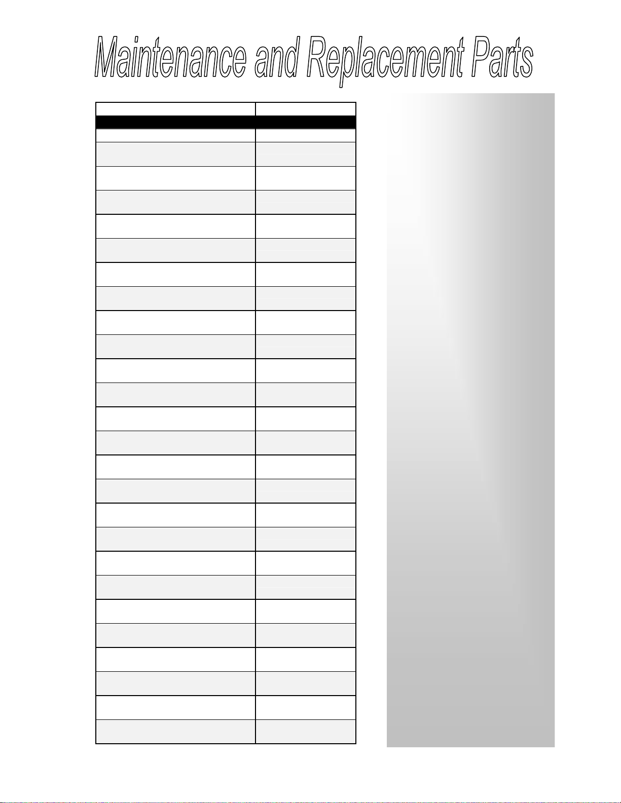
Description Part Number
Air Regulator 18-000
Air Valve 18-001
Air Limit Valve 18-002
Indexing Cylinder Assembly 18-003
Main Air Cylinder 18-004
Carriage Spring –
5/8" Dia. x 5" LG 18-005
Carriage Spring –
1/2" Dia. x 5" LG 18-006
Height Adjustment Knob 18-007
T-Bar Shoe 12-349
T-Bar Clamping Knob Assembly 18-008
Hanger Ram Tip Assembly 18-009
Hanger Shear Nose Assembly 18-010
Ram Guard
(With Arrow Labels) 18-011
Button Head Socket Cap
Screw, #8-32 x 1/2" LG (4) 12-848
Detent Height Settings Bracket &
Scale 18-012
Detent Height Settings Pointer 18-013
Base Assembly (With Scales) 18-014
Flat Head Socket Cap Screw,
#10-32 x 5/8" LG (2) 18-015
Hex Key (Base-To-Frame
Assembly Screws) 18-016
Front Cover Assembly
(With Labels) 18-017
Button Head Socket Cap
Screw, #8-32 x 1/2" LG (4) 12-848
Warning Label
(Guards in Place) 18-018
Caution Label
(Servicing) 18-019
Air Volume Chamber 18-020
Triangle Template (Square) 12-625
ÿThe Saber 250-A is an
efficient and reliable machine,
designedto be operated
safely and maintained with
minimal effort.
ÿKeeping the workarea clean
and clutter-free will allow the
operator to work quickly and
will prevent accidental
damage tothe machine and
production materials.
ÿA clean dry cloth should be
used to wipe down the
machine; the surface of the
base assembly should be
protected from dents and
abrasions. While the machine
will operate properly despite
such marks, it is up to the
operator to safeguard the
condition of your company’s
product by taking care of the
base and fence(s).
ÿThere are no parts to service
or replaceas part of a
regularly scheduled plan. In
fact, there is very little
likelihood that a part will need
replacement.
ÿPlastic safety guards, safety
labels, replacement knobs,
scalesandtheramtipcanbe
ordered from The Fletcher-
Terry Company.
ÿThe machine’s parts and
order numbers are listed to
the left. Please referto the
drawingson page 4to make
sure you are ordering the
correct item.
ÿþýü úù


